EP4277044A1 - Verbindungsvorrichtung und elektrische schalttafel mit einer solchen vorrichtung - Google Patents
Verbindungsvorrichtung und elektrische schalttafel mit einer solchen vorrichtung Download PDFInfo
- Publication number
- EP4277044A1 EP4277044A1 EP23171821.4A EP23171821A EP4277044A1 EP 4277044 A1 EP4277044 A1 EP 4277044A1 EP 23171821 A EP23171821 A EP 23171821A EP 4277044 A1 EP4277044 A1 EP 4277044A1
- Authority
- EP
- European Patent Office
- Prior art keywords
- connection
- terminal
- connection box
- movable wall
- terminal block
- Prior art date
- Legal status (The legal status is an assumption and is not a legal conclusion. Google has not performed a legal analysis and makes no representation as to the accuracy of the status listed.)
- Pending
Links
Images







Classifications
-
- H—ELECTRICITY
- H01—ELECTRIC ELEMENTS
- H01R—ELECTRICALLY-CONDUCTIVE CONNECTIONS; STRUCTURAL ASSOCIATIONS OF A PLURALITY OF MUTUALLY-INSULATED ELECTRICAL CONNECTING ELEMENTS; COUPLING DEVICES; CURRENT COLLECTORS
- H01R13/00—Details of coupling devices of the kinds covered by groups H01R12/70 or H01R24/00 - H01R33/00
- H01R13/62—Means for facilitating engagement or disengagement of coupling parts or for holding them in engagement
- H01R13/639—Additional means for holding or locking coupling parts together, after engagement, e.g. separate keylock, retainer strap
-
- H—ELECTRICITY
- H01—ELECTRIC ELEMENTS
- H01R—ELECTRICALLY-CONDUCTIVE CONNECTIONS; STRUCTURAL ASSOCIATIONS OF A PLURALITY OF MUTUALLY-INSULATED ELECTRICAL CONNECTING ELEMENTS; COUPLING DEVICES; CURRENT COLLECTORS
- H01R9/00—Structural associations of a plurality of mutually-insulated electrical connecting elements, e.g. terminal strips or terminal blocks; Terminals or binding posts mounted upon a base or in a case; Bases therefor
- H01R9/22—Bases, e.g. strip, block, panel
- H01R9/24—Terminal blocks
- H01R9/26—Clip-on terminal blocks for side-by-side rail- or strip-mounting
- H01R9/2675—Electrical interconnections between two blocks, e.g. by means of busbars
-
- H—ELECTRICITY
- H01—ELECTRIC ELEMENTS
- H01H—ELECTRIC SWITCHES; RELAYS; SELECTORS; EMERGENCY PROTECTIVE DEVICES
- H01H1/00—Contacts
- H01H1/58—Electric connections to or between contacts; Terminals
-
- H—ELECTRICITY
- H01—ELECTRIC ELEMENTS
- H01H—ELECTRIC SWITCHES; RELAYS; SELECTORS; EMERGENCY PROTECTIVE DEVICES
- H01H47/00—Circuit arrangements not adapted to a particular application of the relay and designed to obtain desired operating characteristics or to provide energising current
- H01H47/002—Monitoring or fail-safe circuits
-
- H—ELECTRICITY
- H01—ELECTRIC ELEMENTS
- H01H—ELECTRIC SWITCHES; RELAYS; SELECTORS; EMERGENCY PROTECTIVE DEVICES
- H01H47/00—Circuit arrangements not adapted to a particular application of the relay and designed to obtain desired operating characteristics or to provide energising current
- H01H47/002—Monitoring or fail-safe circuits
- H01H47/004—Monitoring or fail-safe circuits using plural redundant serial connected relay operated contacts in controlled circuit
-
- H—ELECTRICITY
- H01—ELECTRIC ELEMENTS
- H01H—ELECTRIC SWITCHES; RELAYS; SELECTORS; EMERGENCY PROTECTIVE DEVICES
- H01H71/00—Details of the protective switches or relays covered by groups H01H73/00 - H01H83/00
- H01H71/08—Terminals; Connections
-
- H—ELECTRICITY
- H01—ELECTRIC ELEMENTS
- H01R—ELECTRICALLY-CONDUCTIVE CONNECTIONS; STRUCTURAL ASSOCIATIONS OF A PLURALITY OF MUTUALLY-INSULATED ELECTRICAL CONNECTING ELEMENTS; COUPLING DEVICES; CURRENT COLLECTORS
- H01R13/00—Details of coupling devices of the kinds covered by groups H01R12/70 or H01R24/00 - H01R33/00
- H01R13/62—Means for facilitating engagement or disengagement of coupling parts or for holding them in engagement
- H01R13/627—Snap or like fastening
- H01R13/6278—Snap or like fastening comprising a pin snapping into a recess
-
- H—ELECTRICITY
- H01—ELECTRIC ELEMENTS
- H01R—ELECTRICALLY-CONDUCTIVE CONNECTIONS; STRUCTURAL ASSOCIATIONS OF A PLURALITY OF MUTUALLY-INSULATED ELECTRICAL CONNECTING ELEMENTS; COUPLING DEVICES; CURRENT COLLECTORS
- H01R13/00—Details of coupling devices of the kinds covered by groups H01R12/70 or H01R24/00 - H01R33/00
- H01R13/62—Means for facilitating engagement or disengagement of coupling parts or for holding them in engagement
- H01R13/629—Additional means for facilitating engagement or disengagement of coupling parts, e.g. aligning or guiding means, levers, gas pressure electrical locking indicators, manufacturing tolerances
-
- H—ELECTRICITY
- H02—GENERATION; CONVERSION OR DISTRIBUTION OF ELECTRIC POWER
- H02B—BOARDS, SUBSTATIONS OR SWITCHING ARRANGEMENTS FOR THE SUPPLY OR DISTRIBUTION OF ELECTRIC POWER
- H02B1/00—Frameworks, boards, panels, desks, casings; Details of substations or switching arrangements
- H02B1/015—Boards, panels, desks; Parts thereof or accessories therefor
- H02B1/04—Mounting thereon of switches or of other devices in general, the switch or device having, or being without, casing
-
- H—ELECTRICITY
- H02—GENERATION; CONVERSION OR DISTRIBUTION OF ELECTRIC POWER
- H02B—BOARDS, SUBSTATIONS OR SWITCHING ARRANGEMENTS FOR THE SUPPLY OR DISTRIBUTION OF ELECTRIC POWER
- H02B1/00—Frameworks, boards, panels, desks, casings; Details of substations or switching arrangements
- H02B1/015—Boards, panels, desks; Parts thereof or accessories therefor
- H02B1/04—Mounting thereon of switches or of other devices in general, the switch or device having, or being without, casing
- H02B1/052—Mounting on rails
-
- H—ELECTRICITY
- H02—GENERATION; CONVERSION OR DISTRIBUTION OF ELECTRIC POWER
- H02B—BOARDS, SUBSTATIONS OR SWITCHING ARRANGEMENTS FOR THE SUPPLY OR DISTRIBUTION OF ELECTRIC POWER
- H02B1/00—Frameworks, boards, panels, desks, casings; Details of substations or switching arrangements
- H02B1/20—Bus-bar or other wiring layouts, e.g. in cubicles, in switchyards
- H02B1/205—Bus-bar or other wiring layouts, e.g. in cubicles, in switchyards for connecting electrical apparatus mounted side by side on a rail
-
- H—ELECTRICITY
- H01—ELECTRIC ELEMENTS
- H01H—ELECTRIC SWITCHES; RELAYS; SELECTORS; EMERGENCY PROTECTIVE DEVICES
- H01H71/00—Details of the protective switches or relays covered by groups H01H73/00 - H01H83/00
- H01H71/08—Terminals; Connections
- H01H71/082—Connections between juxtaposed circuit breakers
Definitions
- the electrical devices When assembling the electrical panel, the electrical devices are mounted on the fixing rails already positioned in the enclosure, then the electrical devices are connected together in a suitable manner. Traditionally, electrical devices are connected to each other by electrical wires, which are inserted one by one by an installer into the corresponding terminals of the electrical devices. The ends of the wires are positioned one by one, if necessary secured by screwing, which takes time.
- the electrical panel 20 conforming to a first embodiment is shown on the figure 1 .
- the electrical panel 20 is configured to connect an electrical power source to one or more electrical loads.
- the electrical power source and electrical loads are not shown.
- the power source is here a three-phase source, that is to say comprising three phases, designated L1, L2 and L3 respectively, and a neutral designated N.
- the electrical loads are a machine tool or a automaton in the context of industrial applications, or even a washing machine or a water heater in the context of domestic applications.
- the electrical panel 20 comprises at least one fixing rail 30.
- the electrical panel 20 comprises three fixing rails 30, which are preferably identical to each other, which are each received in the internal volume V20 and which are fixed to the enclosure 22.
- Each fixing rail 30 has an elongated shape extending parallel to the longitudinal axis X20.
- the enclosure 22 comprises uprights 28A, which are provided vertically along the bottom 24, and supports 28B, which are positioned on the uprights 28A and which are provided for positioning and fixing the fixing rails 30.
- Each fixing rail 30 fixed to the electrical panel 20 is thus arranged parallel to each other, at regular intervals along the height axis Z20.
- the fixing rails 30 include a high rail 30A, located on the top of the figure 1 , a bottom rail 30B, located at the bottom of the figure, and a middle rail 30C, arranged between the top rail 30A and the bottom rail 30B.
- Each fixing rail 30 also includes a counter-rail 34, visible at the figure 2 , which is fixed to the main portion 32 and which extends along the main portion 32, between the main portion 32 and the bottom 24 of the electrical panel 20.
- Each counter rail 34 is configured to carry a distribution device 100 respective, each distribution device 100 then surmounting the corresponding fixing rail 30, as shown on the figures 1 And 2 .
- the electrical device 40 is electrically connected to the distribution device 100 and mechanically mounted on the fixing rail 40.
- table 20 includes an interconnection device 200, which interconnects two distribution devices 100 mounted on neighboring fixing rails 30, here the top rail 30A and the middle rail 30C.
- the electrical devices 40 mounted on the middle rail 30C are connected to the electrical source via the distribution device 100 surmounting the middle rail 30C, the interconnection device 200 and the distribution device 100 surmounting the rail 100.
- the electrical panel 20 comprises three distribution devices 100 identical to each other.
- the axes and directions defined for the electrical panel 20 are used for each distribution device 100 in its configuration of use, such as that represented in the figure 1 , where each distribution device 100 is assembled to a respective fixing rail 30, which are each mounted horizontally in the electrical panel 20.
- the leaf springs 122 are elastically deformable and are configured to pinch the corresponding complementary terminal 44.
- the complementary terminals 44 here have a blade shape, so each connection volume V120 is substantially planar. and extends along a connection plane P120, while the connection axis A120 is parallel to the connection volume V120 and orthogonal to the bottom 123.
- the connection terminals 120 are preferably identical to each other, so as to rationalize their manufacture.
- the distribution device comprises several conductive buses 130.
- the conductive buses 130 are made of a metallic material, preferably a copper alloy, so the conductive buses 130 are sometimes called "coppers".
- the conductive buses 130 extend along the distribution device 100 parallel to the longitudinal axis X20 and are received in the housing 102 while being electrically isolated from each other. others.
- Each conductive bus 130 is configured to be connected, respectively, to a phase L1, L2 or L3 of the power source and to neutral N of the power source, while each connection terminal 120 is connected to one of the conductive buses 130 .
- the transverse buses 134 are separate parts from the main portions, which are manufactured by folding and/or cutting a metal plate and which are welded to the main portions 132, each transverse bus 134 extending parallel to the medium shot P100.
- Each pair 150 includes a connection terminal 120 connected to the neutral bus 130N, and another connection terminal 120 connected to one of the phase buses 130P.
- the six connection terminals 120 located furthest to the left on the front face 104 thus form the pattern 154, which is here a "neutral N - first phase L1 - neutral N - second phase L2 - neutral N - third phase L3”.
- the positions of the neutral and/or the phases are indicated on the front face 104, for example by an alphanumeric character, preferably engraved in the material of the housing 102.
- Each electrical device 40 comprises positioning members, configured to align this electrical device 40 with respect to the pairs 150 when mounting this electrical device on the device
- the distribution device 100 with its particular arrangement of the connection terminals 120 connected to the phases L1, L2 and L3 and to the neutral N of the power source, is particularly advantageous because it makes it possible to easily connect both an electrical device 40 configured to be connected to the three phases and the neutral of the power source, for example the first device 41, than a single-phase electrical device 40, for example the third device 43.
- connection planes P100 are separated by 9 mm. This maintains compatibility with electrical appliances used with single-phase distribution devices of the prior art, in particular with electrical appliances having a width, measured along the longitudinal axis, equal to 18 mm or a multiple of 18 mm. .
- an electrical appliance comprises two complementary terminals 44 configured to be connected to the two connection terminals 120 of two consecutive pairs 150, these two terminals 150 being connected to the phase buses 130P.
- an electrical appliance comprises three complementary terminals 44, including two complementary terminals 44 configured to be connected to two connection terminals 120 connected to the phase buses 130P, and a third complementary terminal 44 configured to be connected to a connection terminal 120 connected to the neutral bus 130N.
- the distribution device 100 also includes two terminal blocks 160.
- the interior of the terminal blocks 160 is visible in particular at the Figure 4 .
- the corresponding terminal plane P210 is parallel to the average plane P100 of this distribution device 100, while the transverse axis X210 is parallel to the longitudinal axis X20, and that each cable 202 is parallel to the height axis Z20.
- the distribution device 100 mounted in the electrical panel 20 in use configuration the set of conductors 204 is located between, on the one hand, the fixing rail 30 and the distribution device 100 and, on the other hand, the bottom 24 of the enclosure 22.
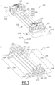
- connection box 230 comprises a movable wall 280, which is tiltably mounted relative to the rest of the connection box 230 and which serves to lock the connection box 230 in the configuration connected to the corresponding terminal block 160.
- the movable wall 280 is described below.
- the total clearance is between 0.3 mm and 1 mm, preferably equal to 0.8 mm.
- the window 288 and the lug 290 are thus an example of an embodiment of a locking member and a complementary locking member, which together form an anti-return member, to maintain the connection box 230 in configuration connected to the corresponding terminal block 160.
- This arrangement is not restrictive.
- the lug is provided on the movable wall 280, while the window 288 is provided on the terminal block 160.
- the lug and the window are replaced by locking and complementary members presenting another form.
- each terminal block 160 comprises several lugs 290, which are each received in a respective window provided on the movable wall 280.
- the lug 290 pushes back the movable wall 280, deforming the elastic element 384 to accommodate the passage of the lug 290.
- the movable wall 280 resumes its locking position by elastic return of the elastic element 384, locking the connection box 230 on the associated terminal block 160 automatically, without requiring an indexing member.
- connection terminals 120 of this pair 150 are connected to the same phase bus 130P.
- the connection terminals 120 which were connected to the neutral bus 130N are rotated on themselves by 180°, around an axis parallel to the depth axis Y20, the connection tab 124 then being connected to the corresponding phase bus 130P .
- connection slot of terminal block 460 being closed, certain connection errors are prevented.
- the interconnection device 200 intended to be connected to the terminal block 160 comprising four input terminals 164, cannot be connected to the terminal block 460 comprising only three input terminals 164.
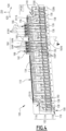
- a dispensing device 500 conforming to an alternative embodiment is shown on the Figure 14 .
- phase buses 130P are made in one piece, for example by cutting and bending a metal plate.
- the main portion 132 and the transverse buses 134 are therefore made in one piece.
- the manufacture of phase buses 130P is simplified compared to phase buses 130 of distribution devices 100 or 400 described previously, but the material scraps are greater.
- a dispensing device 600 conforming to an alternative embodiment is shown on the Figure 15 .
- keying stops are provided on the 3PN type distribution devices, such as the distribution device 100, these keying stops being arranged to interfere with the tabs 703 of the first and second boxes 741 and 742, in other words to prevent the mounting of 3P type devices on a 3PN type distribution device, without preventing the mounting of the third and fourth boxes 743 and 744, in other words to authorize the mounting of 3P type devices on a 3PN type distribution device.
- the window 288 is provided recessed on the movable wall, while the lug 290 is provided on a peripheral wall of the corresponding terminal block 160.
- the lug is visible through the wall, giving the user visual confirmation of the secure connection.
Landscapes
- Engineering & Computer Science (AREA)
- Power Engineering (AREA)
- Physics & Mathematics (AREA)
- Electromagnetism (AREA)
- Connections Arranged To Contact A Plurality Of Conductors (AREA)
- Patch Boards (AREA)
Applications Claiming Priority (1)
| Application Number | Priority Date | Filing Date | Title |
|---|---|---|---|
| FR2204365A FR3135357A1 (fr) | 2022-05-09 | 2022-05-09 | Dispositif d’interconnexion et tableau électrique comprenant un tel dispositif |
Publications (1)
| Publication Number | Publication Date |
|---|---|
| EP4277044A1 true EP4277044A1 (de) | 2023-11-15 |
Family
ID=82693987
Family Applications (1)
| Application Number | Title | Priority Date | Filing Date |
|---|---|---|---|
| EP23171821.4A Pending EP4277044A1 (de) | 2022-05-09 | 2023-05-05 | Verbindungsvorrichtung und elektrische schalttafel mit einer solchen vorrichtung |
Country Status (3)
| Country | Link |
|---|---|
| EP (1) | EP4277044A1 (de) |
| CN (1) | CN117039532A (de) |
| FR (1) | FR3135357A1 (de) |
Citations (4)
| Publication number | Priority date | Publication date | Assignee | Title |
|---|---|---|---|---|
| EP0651481A1 (de) | 1993-10-29 | 1995-05-03 | GARO Aktiebolag | Überbrückungsklemme und eine Methode für ihre Herstellung |
| WO2003067725A1 (de) | 2002-02-07 | 2003-08-14 | Abb Patent Gmbh | Anschluss- oder verteilvorrichtung für elektrische installationsgeräte |
| EP1424756A1 (de) | 2002-11-29 | 2004-06-02 | Schneider Electric Industries Sas | Elektrische Verbindungsanordnung eines electrischen Apparates mit einem modularen Verbindungskamm oder ähnlich |
| EP2182538A1 (de) * | 2008-11-03 | 2010-05-05 | Legrand France | Elektrischer Stecker mit Verriegelungsmitteln |
-
2022
- 2022-05-09 FR FR2204365A patent/FR3135357A1/fr not_active Ceased
-
2023
- 2023-05-05 EP EP23171821.4A patent/EP4277044A1/de active Pending
- 2023-05-08 CN CN202310512973.2A patent/CN117039532A/zh active Pending
Patent Citations (4)
| Publication number | Priority date | Publication date | Assignee | Title |
|---|---|---|---|---|
| EP0651481A1 (de) | 1993-10-29 | 1995-05-03 | GARO Aktiebolag | Überbrückungsklemme und eine Methode für ihre Herstellung |
| WO2003067725A1 (de) | 2002-02-07 | 2003-08-14 | Abb Patent Gmbh | Anschluss- oder verteilvorrichtung für elektrische installationsgeräte |
| EP1424756A1 (de) | 2002-11-29 | 2004-06-02 | Schneider Electric Industries Sas | Elektrische Verbindungsanordnung eines electrischen Apparates mit einem modularen Verbindungskamm oder ähnlich |
| EP2182538A1 (de) * | 2008-11-03 | 2010-05-05 | Legrand France | Elektrischer Stecker mit Verriegelungsmitteln |
Also Published As
| Publication number | Publication date |
|---|---|
| FR3135357A1 (fr) | 2023-11-10 |
| CN117039532A (zh) | 2023-11-10 |
Similar Documents
| Publication | Publication Date | Title |
|---|---|---|
| EP3605749B1 (de) | Halterung für ein elektrisches gerät und entsprechendes elektrisches gerät | |
| EP1041683A1 (de) | Niederspannungsteckverbinder | |
| EP0715375B1 (de) | Modulare elektrische Vorrichtung | |
| EP4277054A1 (de) | Stromverteilungsvorrichtung und elektrische schalttafel mit einer solchen vorrichtung | |
| EP2335263A1 (de) | Elektrische verbindungseinrichtung und schiebebaugruppe insbesondere für eine differenz-schutzeinheit | |
| EP0649158B1 (de) | Differentialschutzblock mit Kabeldurchgang | |
| EP4277044A1 (de) | Verbindungsvorrichtung und elektrische schalttafel mit einer solchen vorrichtung | |
| EP4277053B1 (de) | Verbindungsvorrichtung und elektrische schalttafel mit einer solchen vorrichtung | |
| EP4277055A1 (de) | Verbindungsvorrichtung und elektrische schalttafel mit einer solchen vorrichtung | |
| EP4277052A1 (de) | Stromverteilungsvorrichtung und elektrische schalttafel mit einer solchen vorrichtung | |
| EP2383849B1 (de) | Vertikale elektrisch leitenden Verbindungsvorrichtung | |
| FR2979488A1 (fr) | Barrette de connexion pour le raccordement electrique de deux mecanismes d'appareillage | |
| EP1107363B1 (de) | Monopolarer Modularerverteiler | |
| EP3667845A1 (de) | Fertighalterung für einen elektrischen einschub, und elektrische vorrichtung, die eine solche halterung umfasst | |
| EP1094579B1 (de) | Gerätehalter zur Befestigung mindestens eines elektrischen Geräts auf einem Kabelkanal | |
| EP3255732B1 (de) | Elektrische verbindungsklemme, die einen verbindungshebel umfasst, und entsprechende elektrische geräte | |
| EP2662941B1 (de) | Endeinheit für Verteilereinheit für elektrische Anlage | |
| EP0660461A1 (de) | Mehrfacher Sockel für Steckdose | |
| EP1039604A1 (de) | Verteilungssystem elektrischer Energie in den Stockverken eines Gebäudes | |
| EP4258499A2 (de) | Abgedichtetes elektrisches gerät | |
| FR2900508A1 (fr) | Barre omnibus pour repartition electrique | |
| EP3605750B1 (de) | Mechanismus eines elektrischen geräts und entsprechendes elektrisches gerät | |
| FR2953073A3 (fr) | Dispositif pour relier electriquement au moins deux equipements electriques installes l'un au-dessus de l'autre dans une armoire de distribution electrique | |
| FR2734418A1 (fr) | Connecteur, notamment du type jack modulaire | |
| EP4113751A1 (de) | Verbindungsvorrichtung für den anschluss eines elektrischen geräts an eine stromverteilungsschiene, anordnung mit einer solchen verbindungsvorrichtung und einem solchen elektrischen gerät |
Legal Events
| Date | Code | Title | Description |
|---|---|---|---|
| PUAI | Public reference made under article 153(3) epc to a published international application that has entered the european phase |
Free format text: ORIGINAL CODE: 0009012 |
|
| STAA | Information on the status of an ep patent application or granted ep patent |
Free format text: STATUS: THE APPLICATION HAS BEEN PUBLISHED |
|
| AK | Designated contracting states |
Kind code of ref document: A1 Designated state(s): AL AT BE BG CH CY CZ DE DK EE ES FI FR GB GR HR HU IE IS IT LI LT LU LV MC ME MK MT NL NO PL PT RO RS SE SI SK SM TR |
|
| STAA | Information on the status of an ep patent application or granted ep patent |
Free format text: STATUS: REQUEST FOR EXAMINATION WAS MADE |
|
| 17P | Request for examination filed |
Effective date: 20240417 |
|
| RBV | Designated contracting states (corrected) |
Designated state(s): AL AT BE BG CH CY CZ DE DK EE ES FI FR GB GR HR HU IE IS IT LI LT LU LV MC ME MK MT NL NO PL PT RO RS SE SI SK SM TR |
|
| STAA | Information on the status of an ep patent application or granted ep patent |
Free format text: STATUS: EXAMINATION IS IN PROGRESS |
|
| 17Q | First examination report despatched |
Effective date: 20251112 |