EP4277065A1 - Ladekabelführungssystem - Google Patents
Ladekabelführungssystem Download PDFInfo
- Publication number
- EP4277065A1 EP4277065A1 EP22706103.3A EP22706103A EP4277065A1 EP 4277065 A1 EP4277065 A1 EP 4277065A1 EP 22706103 A EP22706103 A EP 22706103A EP 4277065 A1 EP4277065 A1 EP 4277065A1
- Authority
- EP
- European Patent Office
- Prior art keywords
- motor
- charging
- cable
- suspension cable
- bracket
- Prior art date
- Legal status (The legal status is an assumption and is not a legal conclusion. Google has not performed a legal analysis and makes no representation as to the accuracy of the status listed.)
- Pending
Links
- 239000000725 suspension Substances 0.000 claims abstract description 78
- 238000004804 winding Methods 0.000 claims description 43
- 230000033001 locomotion Effects 0.000 claims description 12
- 238000012545 processing Methods 0.000 claims description 12
- 230000009471 action Effects 0.000 claims description 2
- 239000000446 fuel Substances 0.000 claims description 2
- 230000001737 promoting effect Effects 0.000 claims description 2
- 230000004913 activation Effects 0.000 claims 1
- 238000006073 displacement reaction Methods 0.000 claims 1
- 230000001483 mobilizing effect Effects 0.000 abstract 1
- 238000001514 detection method Methods 0.000 description 6
- 230000000284 resting effect Effects 0.000 description 5
- 238000010586 diagram Methods 0.000 description 3
- 230000007246 mechanism Effects 0.000 description 3
- 238000000034 method Methods 0.000 description 3
- 230000005484 gravity Effects 0.000 description 2
- 230000008859 change Effects 0.000 description 1
- 238000004891 communication Methods 0.000 description 1
- 230000007423 decrease Effects 0.000 description 1
- 238000005516 engineering process Methods 0.000 description 1
- 238000003780 insertion Methods 0.000 description 1
- 230000037431 insertion Effects 0.000 description 1
- 230000003993 interaction Effects 0.000 description 1
- 230000009916 joint effect Effects 0.000 description 1
- 238000011017 operating method Methods 0.000 description 1
- 230000008569 process Effects 0.000 description 1
- 230000001960 triggered effect Effects 0.000 description 1
Images



Classifications
-
- H—ELECTRICITY
- H02—GENERATION; CONVERSION OR DISTRIBUTION OF ELECTRIC POWER
- H02G—INSTALLATION OF ELECTRIC CABLES OR LINES, OR OF COMBINED OPTICAL AND ELECTRIC CABLES OR LINES
- H02G11/00—Arrangements of electric cables or lines between relatively-movable parts
-
- B—PERFORMING OPERATIONS; TRANSPORTING
- B60—VEHICLES IN GENERAL
- B60L—PROPULSION OF ELECTRICALLY-PROPELLED VEHICLES; SUPPLYING ELECTRIC POWER FOR AUXILIARY EQUIPMENT OF ELECTRICALLY-PROPELLED VEHICLES; ELECTRODYNAMIC BRAKE SYSTEMS FOR VEHICLES IN GENERAL; MAGNETIC SUSPENSION OR LEVITATION FOR VEHICLES; MONITORING OPERATING VARIABLES OF ELECTRICALLY-PROPELLED VEHICLES; ELECTRIC SAFETY DEVICES FOR ELECTRICALLY-PROPELLED VEHICLES
- B60L53/00—Methods of charging batteries, specially adapted for electric vehicles; Charging stations or on-board charging equipment therefor; Exchange of energy storage elements in electric vehicles
- B60L53/10—Methods of charging batteries, specially adapted for electric vehicles; Charging stations or on-board charging equipment therefor; Exchange of energy storage elements in electric vehicles characterised by the energy transfer between the charging station and the vehicle
- B60L53/14—Conductive energy transfer
- B60L53/18—Cables specially adapted for charging electric vehicles
-
- B—PERFORMING OPERATIONS; TRANSPORTING
- B60—VEHICLES IN GENERAL
- B60L—PROPULSION OF ELECTRICALLY-PROPELLED VEHICLES; SUPPLYING ELECTRIC POWER FOR AUXILIARY EQUIPMENT OF ELECTRICALLY-PROPELLED VEHICLES; ELECTRODYNAMIC BRAKE SYSTEMS FOR VEHICLES IN GENERAL; MAGNETIC SUSPENSION OR LEVITATION FOR VEHICLES; MONITORING OPERATING VARIABLES OF ELECTRICALLY-PROPELLED VEHICLES; ELECTRIC SAFETY DEVICES FOR ELECTRICALLY-PROPELLED VEHICLES
- B60L53/00—Methods of charging batteries, specially adapted for electric vehicles; Charging stations or on-board charging equipment therefor; Exchange of energy storage elements in electric vehicles
- B60L53/30—Constructional details of charging stations
- B60L53/31—Charging columns specially adapted for electric vehicles
-
- H—ELECTRICITY
- H02—GENERATION; CONVERSION OR DISTRIBUTION OF ELECTRIC POWER
- H02G—INSTALLATION OF ELECTRIC CABLES OR LINES, OR OF COMBINED OPTICAL AND ELECTRIC CABLES OR LINES
- H02G11/00—Arrangements of electric cables or lines between relatively-movable parts
- H02G11/02—Arrangements of electric cables or lines between relatively-movable parts using take-up reel or drum
-
- H—ELECTRICITY
- H02—GENERATION; CONVERSION OR DISTRIBUTION OF ELECTRIC POWER
- H02G—INSTALLATION OF ELECTRIC CABLES OR LINES, OR OF COMBINED OPTICAL AND ELECTRIC CABLES OR LINES
- H02G11/00—Arrangements of electric cables or lines between relatively-movable parts
- H02G11/003—Arrangements of electric cables or lines between relatively-movable parts using gravity-loaded or spring-loaded loop
-
- Y—GENERAL TAGGING OF NEW TECHNOLOGICAL DEVELOPMENTS; GENERAL TAGGING OF CROSS-SECTIONAL TECHNOLOGIES SPANNING OVER SEVERAL SECTIONS OF THE IPC; TECHNICAL SUBJECTS COVERED BY FORMER USPC CROSS-REFERENCE ART COLLECTIONS [XRACs] AND DIGESTS
- Y02—TECHNOLOGIES OR APPLICATIONS FOR MITIGATION OR ADAPTATION AGAINST CLIMATE CHANGE
- Y02T—CLIMATE CHANGE MITIGATION TECHNOLOGIES RELATED TO TRANSPORTATION
- Y02T10/00—Road transport of goods or passengers
- Y02T10/60—Other road transportation technologies with climate change mitigation effect
- Y02T10/70—Energy storage systems for electromobility, e.g. batteries
-
- Y—GENERAL TAGGING OF NEW TECHNOLOGICAL DEVELOPMENTS; GENERAL TAGGING OF CROSS-SECTIONAL TECHNOLOGIES SPANNING OVER SEVERAL SECTIONS OF THE IPC; TECHNICAL SUBJECTS COVERED BY FORMER USPC CROSS-REFERENCE ART COLLECTIONS [XRACs] AND DIGESTS
- Y02—TECHNOLOGIES OR APPLICATIONS FOR MITIGATION OR ADAPTATION AGAINST CLIMATE CHANGE
- Y02T—CLIMATE CHANGE MITIGATION TECHNOLOGIES RELATED TO TRANSPORTATION
- Y02T10/00—Road transport of goods or passengers
- Y02T10/60—Other road transportation technologies with climate change mitigation effect
- Y02T10/7072—Electromobility specific charging systems or methods for batteries, ultracapacitors, supercapacitors or double-layer capacitors
-
- Y—GENERAL TAGGING OF NEW TECHNOLOGICAL DEVELOPMENTS; GENERAL TAGGING OF CROSS-SECTIONAL TECHNOLOGIES SPANNING OVER SEVERAL SECTIONS OF THE IPC; TECHNICAL SUBJECTS COVERED BY FORMER USPC CROSS-REFERENCE ART COLLECTIONS [XRACs] AND DIGESTS
- Y02—TECHNOLOGIES OR APPLICATIONS FOR MITIGATION OR ADAPTATION AGAINST CLIMATE CHANGE
- Y02T—CLIMATE CHANGE MITIGATION TECHNOLOGIES RELATED TO TRANSPORTATION
- Y02T90/00—Enabling technologies or technologies with a potential or indirect contribution to GHG emissions mitigation
- Y02T90/10—Technologies relating to charging of electric vehicles
- Y02T90/14—Plug-in electric vehicles
Definitions
- the present invention concerns a charging cable management system, which is motorized and is applied in electric vehicle charging equipment, or other applications that require this type of solution.
- the solution presented by the present invention allows the user charging interface to provide a unique charging experience, as no force will be required to handle and hold the charging cable.
- the charging cable management system of the present invention will provide more charging cable according to the need, as well as proceed with the collection thereof, requiring no effort on the part of the user.
- US6338450B1 describes a cable manager having a support member and a bracket that mounts the support member to a ceiling joist of a golf cart shed.
- the first pulley wheel attaches to the top end of the support member, and a second pulley wheel attaches to a pulley mounting bracket.
- a coil spring entrained about the first pulley wheel has one end attached to the pulley mounting bracket and the other end attached to the bottom end of the support member.
- the second pulley wheel is suspended at a lower elevation than the first pulley wheel and moves down against the force of the spring when the power cable entrained over it is pulled down to connect to a golf cart for recharging.
- the lower pulley While recharging occurs, the lower pulley is fixed to the support member by attaching its bracket to an S-hook that attaches the spring to the vertical support member. When the power cable is released, the pulley moves up but its upward travel is limited by a cable bracket that captures the power cable and holds it in position for easy retrieval for the next use.
- the present application describes an electric vehicle charging cable management system comprising a motorized winding system for a suspension cable, wherein the motorized winding system is adapted to control the provision of the suspension cable that guarantees the support and suspension of the electric vehicle charging cable.
- the motorized winding system comprises a longitudinal U-shaped rail with two ends, inside which a guide runs longitudinally comprising a vertical hole passing through its central core and which is physically and mechanically adapted to the shape of the rail allowing its free movement between the two ends of the rail, wherein the base of said rail comprises a longitudinal cutout coincident with the positioning and alignment of the vertical hole of the guide, the rail comprising at one of its ends an offset sensor A, and at the opposite end another offset sensor B; a U-shaped bracket comprising a threaded shaft, a motor, limit switch sensors A and B, the threaded shaft mechanically adapted to the bracket comprises a movable guide, the motor mechanically adapted to the threaded shaft in order to promote its rotation is fixed to the bracket, the limit switch sensors A and B fixed to the bracket are positioned in order to determine the positioning of the movable guide, and the rail being fixed to said bracket; a reel, positioned above the rail and mechanically adapted to the threaded shaft in order to accompany its
- the motor is mechanically adapted to the threaded shaft by means of a rotor.
- the offset sensors A and B detect the contact of the guide with the respective end of the rail, promoting the actuation of the motor.
- the contact of the guide with the offset sensor A promotes the rotation of the motor in one direction
- the contact of the guide with the offset sensor B promotes the rotation of the motor in the same direction corresponding to the unwinding of the suspension cable.
- the limit switch sensors A and B detect the contact of the movable guide running along the threaded shaft with the ends of the bracket.
- the reel promotes the winding or unwinding of the suspension cable through the action generated by the motor.
- the contact of the movable guide with the limit switch sensor A or the limit switch sensor B identifies the winding or unwinding position of the cable on the reel.
- the proposed system comprises an outer housing with an open groove in its base that allows the suspension cable to pass through and be handled.
- the proposed charging cable management system comprises a control system consisting of a signal acquisition and processing unit, a processing and control unit and an output signal for motor control; a control system; and a DC power supply.
- the proposed system comprises a sensor system composed of motor current sensors and connector rest sensors.
- control system receives the signals from the sensor system through the signal acquisition unit, performing the signal processing in the processing unit which sends the output signal to the motor control system.
- the output signal actuates the control system through the use of an H-bridge, which promotes the rotation of the motor in one direction, closing a MOSFET Q3-Q2 circuit, or promotes the rotation of the motor in the opposite direction closing a MOSFET Q1-Q4 circuit.
- the present document further describes an electric vehicle charging system characterized in that it comprises at least one previously described electric vehicle charging cable management system, and at least one charging cable with a charging connector; wherein the charging cable is supported by the suspension cable of the motorized winding system ensuring that it does not come into contact with the ground when not in use.
- the proposed system could also be implemented in fuel supply pumps or other types of hose bracket.
- the present invention concerns a cable management system, in particular cables for charging electric vehicles, using a motorized system.
- the present solution is intended for application in electric vehicle charging stations, when there is a need to use longer charging cables and can additionally serve as a solution for any other type of application requiring this type of innovation.
- the objective of the present charging cable management system is to improve the handling of the charging cable of electric vehicle charging stations, minimizing the efforts by the user, also guaranteeing the integrity and durability of said charging cable once that it does not come into contact with the ground.
- any charging station to guarantee the availability of longer charging cables that allow reaching farther positions of the input connector in the vehicle, these are often in contact with the ground at least at a point along their entire length when not are in use and at rest, so such use of the charging cable promotes wear and tear thereof, reducing its useful life, and jeopardizing the safety of the user.
- the present solution uses a motorized charging cable management system, which prevents the electric charging cable from contacting or resting on the ground.
- the system is also different in that it does not wind the electric charging cable, but rather an auxiliary cable for suspending the electric charging cable.
- the motorized system features controlled strength and speed.
- the system bracket that holds it, promotes its release in a controlled way until no more charging cable is needed.
- the user finishes the charging session and removes the connector from the vehicle he places it in the resting position of the charging station, and the system automatically retracts the charging cable, requiring no intervention by the user.
- the present application therefore describes a system for tensioning and retracting electric vehicle charging cables, comprising:
- the cable tensioning and retraction system identifies that the connector is no longer at rest and starts evaluating the need to supply a charging cable to the user.
- the system detects the angular movement of the charging cable, the motor is activated acting on the reel where the support cable is wound, which promotes the unwinding of the suspension cable.
- the system motor is immobilized as soon as it is no longer necessary to supply more charging cable to the user or upon detection that the suspension cable is fully unwound.
- the motor is actuated, this time in the retraction direction of the suspension cable until the entire charging cable is collected.
- the motor is immobilized, and the system enters idle mode.
- the charging connector (104) is inactive and placed in the rest bracket of the charging station (100), causing the charging cable (102) to be retracted and the cable suspension (103) completely wound onto the reel (1033) of the motorized winding system (101).
- FIG 2 the first interaction of the user (200) with the charging station (100) is depicted.
- the user (200) pulls the charging connector (104) towards the electric vehicle, the charging cable (102) being suspended in the air without coming into contact with the ground.
- the motorized winding system (101) detects that more charging cable (102) is being requested by the user (200).
- the suspension cable (103) is responsible for guaranteeing the lift and support of the charging cable (102), preventing it from coming into contact with the ground when the user (200) moves the charging connector (104) towards the vehicle to be loaded.
- the motorized winding system (101) will unwind the suspension cable (103) from the reel (1033).
- the motorized winding system (101) detects, through the offset detectors A and B (1034, 1039), that no more charging cable (102) is being requested, and since the suspension cable (103) is vertical to the charging station (100), offset sensors A and B (1034, 1039) will not activate.
- the motor (1014) is immobilized, and the suspension cable bracket (105) is responsible for guaranteeing the lift of the charging cable (102), allowing sufficient slack and tension for the user (200) to guarantee the insertion of the charging connector (104) in the vehicle.
- the charging cable management system solution proposed by the present invention is composed of the motorized winding system (101), which comprises a DC power supply (1011), a command system (1013), control system (1017), overcurrent protection (1012), a DC motor, DC (1014) with gearbox, a mechanical system, rotor (10141) and sensor system (1016) .
- the innovation of the solution proposed by the present invention involves the use of a direct current operating motor (1014) to promote the winding and unwinding of the suspension cable (103) that supports the charging cable (102), allowing the latter to have greater extension and consequent greater reach.
- the suspension cable (103) supports the charging cable (102) through the suspension cable holder (105).
- the motor (1014) is mechanically connected to a reel (1033) where the suspension cable (103) is wound and unwound.
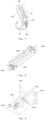
- An exploded view of the motorized winding system (101) developed is shown in figure 6 .
- the motorized winding system (101) allows the application and operation with different types of charging cables (102) such as CCS and CHAdeMO of different diameters and weights, either cooled or not.
- the proposed motorized winding system (101) has the possibility to change the necessary parameters to compensate for the different charging cables (102) and maintain speed and ease of use regardless of the type of charging cable.
- the groove incorporated in the rail (1031) has been designed in such a way that the suspension cable (103) always slides until one of the offset detectors A and B (1034, 1039) triggers.
- the motorized winding system (101) validates the status of the limit switch sensors A and B (10351, 10352) installed on the bracket (1036) as shown in Figure 9 .
- the movable guide (1037) abuts one of the identified points (A or B) and triggers one of the limit switch sensors A or B (10351 or 10352). Likewise, in case the suspension cable (103) is fully unwound, the movable guide (1037) will abut the opposite point (A or B), triggering the other limit switch sensor A or B (10351 or 10352).
- the motorized winding system (101) analyzes the status of the limit switch sensors A and B (10351, 10352) to determine whether the suspension cable (103) is fully wound on the reel (1033) or fully extended on the vertical position to the charging station (100), and together with the two offset sensors A and B (1034, 1039), it validates whether the release of more charging cable (103) is being requested and whether there are conditions to comply with the user's request (200) .
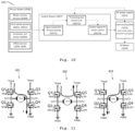
- the sensor system (1016), referred to in Figure 10 is composed of: motor current sensors (10350), which validate whether its operation is taking place within normal operating patterns; limit switch sensors A and B (10351, 10352), which provide information to the motorized winding system (101) on the winding status of the suspension cable (103) about the reel (1033); offset sensors A and B (1034, 1039), in joint action, allow to validate whether or not there is a suspension cable (103) release request; and rest sensor (10353) of the charging connector (104) on the charging station rest bracket (100), determines the initial and final operating condition of the charging cable management system, so that the motorized winding system (101) dispenses or winds the suspension cable (103).
- MOSFET closing circuit Q3-Q2
- MOSFET closing circuit Q1-Q4
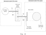
- the basic concept of the charging cable management system of the present invention involves the use of a model with a motor (1014) associated with a reel (1033), which pulls or releases a weight according to the rotational direction of the motor axis (1014).
- the motor is connected to a rotor (10141), which changes the relationship between speed and torque.
- the threaded output shaft (1035) of the rotor (10141) is coupled to a reel (1033), where the suspension cable (103) is wound or unwound.
- Figure 13 shows the functional flowchart of the charging cable management system and its conditional operating method.
- the motorized winding system (101) detects that the charging connector (104) is not installed on the charging station's rest bracket (100), through information from the rest sensor (10353), the motorized winding system (101) validates the status of the offset detectors A and B (1034, 1039), to assess whether the charging cable (102), and in particular the suspension cable (103), is being pulled by the user (200). If offset detectors A and B (1034, 1039) are triggered, then the motorized winding system (101) will validate whether there is suspension cable (103) to supply or retrieve. This information is determined through the data from the limit switch sensors A and B (10351, 10352).
- the motorized winding system (101) will actuate the rotation movement of the central shaft of the motor (1014), in order to provide (unwind) the suspension cable (103) .
- the motor shaft (1014) rotates in the rotation direction which promotes the provision of the suspension cable (103).
- the motorized winding system (101) validates whether the charging connector (104) is connected to the vehicle for charging the electric vehicle. If the condition is verified, the threaded shaft (1035) of the motor (1014) remains immovable, and there is no need to supply more suspension cable (103) .
- the motorized winding system (101) assesses whether the charging session has already been completed. In the event that the charging connector (104) returns to the resting position, then the charging session is considered to be completed and the motorized winding system (101) proceeds to the phase of validating the presence of suspension cable (103) to retract.
- the motorized winding system (101) incorporates a timer, which allows the user (200) time to step away so that the system retracts the suspension cable (103) safely.
- the suspension cable (103) is retracted, while the charging connector (104) remains in the rest position and there is suspension cable (103) to retract.
- the motorized winding system (101) detects, through limit switch sensors A or B (10351, 10352) that the suspension cable (103) is fully wound, then the cycle ends, and the threaded shaft (1035) of the motor (1014) is immobilized.
- the motor drive circuit (1014), as illustrated in figure 11 is based on an electrical converter with H-bridge configuration. This converter allows driving the motor (1014) clockwise or counterclockwise according to the MOSFET states (Q1, Q2, Q3, Q4), as well as controlling the rotation speed of the motor (1014) using the Pulse-Width Modulation (PWM) technique.
- PWM Pulse-Width Modulation
- a closed loop current control system is used.
- the reference current used for controlling the motor (1014) is adapted to the weight of the charging cable (102), thus limiting the torque of the motor (1014) to what is essential to move the charging cable (102) .
Landscapes
- Engineering & Computer Science (AREA)
- Power Engineering (AREA)
- Transportation (AREA)
- Mechanical Engineering (AREA)
- Charge And Discharge Circuits For Batteries Or The Like (AREA)
- Electric Propulsion And Braking For Vehicles (AREA)
Applications Claiming Priority (2)
| Application Number | Priority Date | Filing Date | Title |
|---|---|---|---|
| PT11699321 | 2021-01-07 | ||
| PCT/IB2022/050116 WO2022149096A1 (pt) | 2021-01-07 | 2022-01-07 | Sistema de gestão de cabo de carregamento |
Publications (1)
| Publication Number | Publication Date |
|---|---|
| EP4277065A1 true EP4277065A1 (de) | 2023-11-15 |
Family
ID=80448745
Family Applications (1)
| Application Number | Title | Priority Date | Filing Date |
|---|---|---|---|
| EP22706103.3A Pending EP4277065A1 (de) | 2021-01-07 | 2022-01-07 | Ladekabelführungssystem |
Country Status (3)
| Country | Link |
|---|---|
| US (1) | US20240067010A1 (de) |
| EP (1) | EP4277065A1 (de) |
| WO (1) | WO2022149096A1 (de) |
Families Citing this family (6)
| Publication number | Priority date | Publication date | Assignee | Title |
|---|---|---|---|---|
| WO2024156047A1 (en) * | 2023-01-26 | 2024-08-02 | AddÉnergie Technologies Inc. | Cable management system tension sensing using transfer lever |
| SE2350269A1 (en) * | 2023-03-10 | 2024-04-02 | Dover Fueling Solutions Uk Ltd | Electric vehicle charger and method for managing a charging cable |
| KR102814236B1 (ko) * | 2023-09-04 | 2025-05-30 | 엘지전자 주식회사 | 충전기 및 그 제어 방법 |
| KR102814233B1 (ko) * | 2023-09-04 | 2025-05-30 | 엘지전자 주식회사 | 충전기 |
| KR102855549B1 (ko) * | 2024-07-03 | 2025-09-05 | 에스케이일렉링크 주식회사 | 충전 케이블의 파손을 방지하고, 충전 구역에서의 불법 주차를 감소시키는 가로등형 전기 차량 충전기 |
| CN121236064A (zh) * | 2025-11-27 | 2025-12-30 | 捷迅技术(广州)有限公司 | 充电枪线缆复位的预判方法、系统、可读存储介质及设备 |
Family Cites Families (5)
| Publication number | Priority date | Publication date | Assignee | Title |
|---|---|---|---|---|
| DE102011017570B4 (de) * | 2011-04-27 | 2013-04-04 | Siemens Aktiengesellschaft | Anordnung und Verfahren zur Arretierung einer Aufrollautomatik eines Ladekabels für ein Elektrofahrzeug |
| CN207243452U (zh) * | 2017-09-28 | 2018-04-17 | 北京长吉加油设备有限公司 | 由电机驱动的加油机胶管收放器 |
| KR102020277B1 (ko) * | 2017-11-27 | 2019-09-11 | 인우시스템 주식회사 | 전기 자동차 충전용 케이블 제어장치 및 대기부스를 구비한 전기 자동차 충전기 용 캐노피 |
| CN209113468U (zh) * | 2018-10-25 | 2019-07-16 | 安徽中升智能科技有限公司 | 一种电动伸缩加油管 |
| US11685277B1 (en) * | 2022-08-18 | 2023-06-27 | Beta Air, Llc | Electric vehicle charger for an electric vehicle and a method of use |
-
2022
- 2022-01-07 EP EP22706103.3A patent/EP4277065A1/de active Pending
- 2022-01-07 US US18/271,211 patent/US20240067010A1/en active Pending
- 2022-01-07 WO PCT/IB2022/050116 patent/WO2022149096A1/pt not_active Ceased
Also Published As
| Publication number | Publication date |
|---|---|
| US20240067010A1 (en) | 2024-02-29 |
| WO2022149096A1 (pt) | 2022-07-14 |
Similar Documents
| Publication | Publication Date | Title |
|---|---|---|
| US20240067010A1 (en) | Charging cable management system | |
| CN109565169B (zh) | 具有电缆管理单元的顶置式充电系统 | |
| US11853037B2 (en) | Electric hoisting machine and control device and control method therefor | |
| CN111108058A (zh) | 用于提升和/或降下尤其是起重机的升降机的负载装卸机构的方法及其升降机 | |
| JP2008254927A (ja) | ケーブルシステム | |
| CN114056176A (zh) | 换电装置、换电站及换电方法 | |
| CN111044250A (zh) | 绳索张紧装置、全机颤振风洞试验系统和试验方法 | |
| CN111717802A (zh) | 一种基于5g技术的超高层幕墙吊装系统 | |
| CN113291182A (zh) | 智能可移动式直流快速充电桩和智能充电方法 | |
| CN110668107A (zh) | 带式输送机故障巡检载具及其控制系统和控制方法 | |
| US6003842A (en) | Installation for putting in electrical cable for indoor installations | |
| CN216636205U (zh) | 换电装置及换电站 | |
| JPH04295215A (ja) | 接地線の自動接地装置 | |
| JP5425072B2 (ja) | スライドドア等のリニア駆動部 | |
| EP3746392B1 (de) | Hebevorrichtung zum anheben eines objekts | |
| EP3533751A1 (de) | Winde | |
| CN113247710B (zh) | 线缆收放装置、线缆收放方法及移动机器人 | |
| KR20190130896A (ko) | Ev 충전장치 | |
| CN216954604U (zh) | 绳缆断股断绳监测安装结构 | |
| KR100396445B1 (ko) | 곤도라로 케이블을 포설하는 장치 | |
| JP2002017012A (ja) | ハンガーローラ及びケーブルの架線工法 | |
| CN224091435U (zh) | 电梯救援装置和电梯 | |
| WO2024156047A1 (en) | Cable management system tension sensing using transfer lever | |
| CN223060414U (zh) | 收线装置以及充电桩 | |
| CN113037656A (zh) | 一种网络交换机用智能化固定装置 |
Legal Events
| Date | Code | Title | Description |
|---|---|---|---|
| STAA | Information on the status of an ep patent application or granted ep patent |
Free format text: STATUS: UNKNOWN |
|
| STAA | Information on the status of an ep patent application or granted ep patent |
Free format text: STATUS: THE INTERNATIONAL PUBLICATION HAS BEEN MADE |
|
| PUAI | Public reference made under article 153(3) epc to a published international application that has entered the european phase |
Free format text: ORIGINAL CODE: 0009012 |
|
| STAA | Information on the status of an ep patent application or granted ep patent |
Free format text: STATUS: REQUEST FOR EXAMINATION WAS MADE |
|
| 17P | Request for examination filed |
Effective date: 20230801 |
|
| AK | Designated contracting states |
Kind code of ref document: A1 Designated state(s): AL AT BE BG CH CY CZ DE DK EE ES FI FR GB GR HR HU IE IS IT LI LT LU LV MC MK MT NL NO PL PT RO RS SE SI SK SM TR |
|
| DAV | Request for validation of the european patent (deleted) | ||
| DAX | Request for extension of the european patent (deleted) |