EP4277116A1 - Verfahren und systeme zur überwachung einer elektrischen maschine - Google Patents
Verfahren und systeme zur überwachung einer elektrischen maschine Download PDFInfo
- Publication number
- EP4277116A1 EP4277116A1 EP22173330.6A EP22173330A EP4277116A1 EP 4277116 A1 EP4277116 A1 EP 4277116A1 EP 22173330 A EP22173330 A EP 22173330A EP 4277116 A1 EP4277116 A1 EP 4277116A1
- Authority
- EP
- European Patent Office
- Prior art keywords
- electrical machine
- machine
- electrical
- efficiency
- energy consumption
- Prior art date
- Legal status (The legal status is an assumption and is not a legal conclusion. Google has not performed a legal analysis and makes no representation as to the accuracy of the status listed.)
- Withdrawn
Links
Images


Classifications
-
- H—ELECTRICITY
- H02—GENERATION; CONVERSION OR DISTRIBUTION OF ELECTRIC POWER
- H02P—CONTROL OR REGULATION OF ELECTRIC MOTORS, ELECTRIC GENERATORS OR DYNAMO-ELECTRIC CONVERTERS; CONTROLLING TRANSFORMERS, REACTORS OR CHOKE COILS
- H02P23/00—Arrangements or methods for the control of AC motors characterised by a control method other than vector control
- H02P23/14—Estimation or adaptation of motor parameters, e.g. rotor time constant, flux, speed, current or voltage
-
- G—PHYSICS
- G06—COMPUTING OR CALCULATING; COUNTING
- G06Q—INFORMATION AND COMMUNICATION TECHNOLOGY [ICT] SPECIALLY ADAPTED FOR ADMINISTRATIVE, COMMERCIAL, FINANCIAL, MANAGERIAL OR SUPERVISORY PURPOSES; SYSTEMS OR METHODS SPECIALLY ADAPTED FOR ADMINISTRATIVE, COMMERCIAL, FINANCIAL, MANAGERIAL OR SUPERVISORY PURPOSES, NOT OTHERWISE PROVIDED FOR
- G06Q10/00—Administration; Management
- G06Q10/06—Resources, workflows, human or project management; Enterprise or organisation planning; Enterprise or organisation modelling
-
- G—PHYSICS
- G06—COMPUTING OR CALCULATING; COUNTING
- G06Q—INFORMATION AND COMMUNICATION TECHNOLOGY [ICT] SPECIALLY ADAPTED FOR ADMINISTRATIVE, COMMERCIAL, FINANCIAL, MANAGERIAL OR SUPERVISORY PURPOSES; SYSTEMS OR METHODS SPECIALLY ADAPTED FOR ADMINISTRATIVE, COMMERCIAL, FINANCIAL, MANAGERIAL OR SUPERVISORY PURPOSES, NOT OTHERWISE PROVIDED FOR
- G06Q50/00—Information and communication technology [ICT] specially adapted for implementation of business processes of specific business sectors, e.g. utilities or tourism
- G06Q50/06—Energy or water supply
-
- H—ELECTRICITY
- H02—GENERATION; CONVERSION OR DISTRIBUTION OF ELECTRIC POWER
- H02K—DYNAMO-ELECTRIC MACHINES
- H02K11/00—Structural association of dynamo-electric machines with electric components or with devices for shielding, monitoring or protection
- H02K11/20—Structural association of dynamo-electric machines with electric components or with devices for shielding, monitoring or protection for measuring, monitoring, testing, protecting or switching
-
- H—ELECTRICITY
- H02—GENERATION; CONVERSION OR DISTRIBUTION OF ELECTRIC POWER
- H02P—CONTROL OR REGULATION OF ELECTRIC MOTORS, ELECTRIC GENERATORS OR DYNAMO-ELECTRIC CONVERTERS; CONTROLLING TRANSFORMERS, REACTORS OR CHOKE COILS
- H02P2207/00—Indexing scheme relating to controlling arrangements characterised by the type of motor
- H02P2207/01—Asynchronous machines
Definitions
- the subject matter disclosed herein relates to methods and systems for monitoring of an electrical machine.
- the subject matter disclosed herein relates to a computer program comprising instructions to cause the above-mentioned system to execute the above-mentioned method and to a computer-readable medium having stored thereon such computer program.
- IIoT devices e.g., soft sensors, used for condition monitoring can usually provide only motor torque and motor speed, which are not sufficient to determine motor efficiency and hence motor energy consumption.
- Subject matter disclosed herein provides a solution to the above-stated problems in form of a method for monitoring of an electrical, e.g., electrical rotatory machine, in particular of a plurality (two, three, ten, hundred or even more) of electrical machines, during its (their) operation, in particular in its continuous operation.
- an electrical e.g., electrical rotatory machine
- a plurality two, three, ten, hundred or even more
- the method comprises steps of detecting, in a detector, a stray magnetic field of the electrical machine (of each electrical machine); based on the detected stray magnetic field and on an electrical model of the electrical machine, determining operating point data of the electrical machine; using the electrical model and the operating point data to determine a mechanical output power p mech ( t ) and power losses p losses ( t ) of the electrical machine; and determining (by continuous, in particular uninterrupted calculation during machine's operation) an efficiency ⁇ ( t ) of the electrical machine from the mechanical output power and from the power losses.
- the method allows a load-dependent calculation of the efficiency of the electrical machine during its operation.
- the term operation here means that the electrical machine is in use as a field device in a factory, automation facility or plant, i.e., a place, where the load of the electrical machine varies. This implies that no additional equipment can be used to monitor each and every electrical machine. This would introduce additional costs, but, most importantly, is very time consuming.
- a change of a load of an electrical machine is multidimensional problem and a variety of quantities can influence losses of the machine, e.g., torque, rotational speed, thermal conditions, and a few more. This implies that the electrical machine usually operates in a dynamical environment and its real efficiency deviates from the efficiency that was measured in a standardized procedure under standardized conditions during a machine's type test, away from the individual operation under real world conditions.
- the power losses p losses ( t ) comprise but are not limited to ohmic losses of stator and rotor, core losses, windage and friction losses, load dependent additional losses.
- the detector comprises a magnetic field detector for receiving the stray magnetic field.
- the stray magnetic field encompasses characteristic frequencies.
- a stator frequency i.e., a frequency of the currents in the stator winding
- a frequency of the currents in rotor winding can be determined from the stray magnetic field. These two frequencies can be used to determine rotational speed, slip and further quantities relevant for determining the operating point of the electrical machine.
- the method further comprises visualizing the energy efficiency of the electrical machine as a function of time.
- the method further comprises, if the energy efficiency is lower than some predetermined threshold value, notifying the undercutting of the threshold value.
- the method further comprises:
- the method further comprises, if the reference electrical machine is more efficient than the electrical machine, recommending, e.g., regularly recommending the use of the more efficient further electrical machine.
- the method comprises recommending, e.g., recommending regularly to optimize the efficiency of the electrical machine.
- the recommendation comprises visualization of a carbon footprint of the electrical machine, wherein the carbon footprint is calculated based on the machine's efficiency.
- the recommendation can comprise a recommendation of a change in the operating conditions of the machine, e.g., it can be recommended to changes the voltage/flux (of the inverter of the electrical machine), the load (e.g., to reduce it, if the machine works in overload, or to increase it, if the machine works in underload), etc.
- the method further comprises calculating a reference energy consumption of the reference electrical machine and an energy consumption of the (original) electrical machine for a predetermined time interval and comparing the reference energy consumption of the reference electrical machine with the energy consumption of the (original) electrical machine.
- the method further comprises receiving, e.g., in an acceleration detector, mechanical vibrations of the electrical machine and using detected mechanical vibrations to determine the operating point data. From mechanical vibrations, by performing a spectral analysis, the rotational speed of the rotor can be determined directly. In this case the method is faster.
- the detector comprises an acceleration detector.
- the determining the operating point data of the electrical machine comprises determining rotational speed and torque of the electrical machine.
- the electrical model is designed as an extended equivalent circuit.
- the extended equivalent circuit comprises, among other machine-specific parameters (main inductance X h (main flux), stator leakage inductance X 1 and rotor leakage inductance X' 2 (leakage flux), rotor resistance R' 2 (for rotor winding losses), stator resistance R 1 (for stator winding losses), R fe (for core losses)), an additional resistance R add that is responsible for additional losses.
- the losses can be determined by solving the extended equivalent circuit and calculating the power on corresponding resistances.
- the method further comprises determining parameters of the extended equivalent circuit from/by using nameplate data.
- the problem is also solved by providing a system having a detector for detecting a stray magnetic field of an electrical machine and a computing device adapted to perform the above-described method.
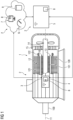
- FIG 1 shows an electric rotary machine 1.
- the machine 1 is connected to an operating voltage and is in operation.
- the machine 1 is designed as an asynchronous machine, for example as an asynchronous motor, and has a rotor 10 rotatable about a rotation axis 11 and a stator 12 surrounding the rotor 10, wherein a gap 13, which is designed in particular as an air gap, is located between the rotor 10 and the stator 12.
- the axis of rotation 11 defines an axial direction and a radial direction.
- the rotor 10 comprises a shaft 100 and a rotor laminate package 101.
- the stator 12 comprises a stator laminate package 120 with stator windings 121, wherein the stator laminate stack 120 is constructed from a plurality of laminated electrical sheets.
- stator windings 121 extend axially through the stator laminate stack 120 and form winding heads 122 at the axial ends of the stator laminate package 120.
- the shaft 100 of the rotor 10 is supported by bearings 14.
- the rotor 10 and the stator 12 are housed in a closed machine housing 15.
- FIG 1 further illustrates a system 2 for monitoring of the electrical rotatory machine 1 during its operation.
- the system 2 comprises a sensor device 3 - a detector - and a computing system 4, 5, 6, 7.
- the computing device 4, 5, 6, 7 may generally comprise hardware and/or software components. For example, it may comprise a first 4 and a second hardware component 5, a displaying device 6 and a cloud computing unit 7.
- the hardware components (computing units) 4, 5, the displaying device 6, and the cloud computing unit 7 may all be structurally separated from each other.
- the sensor device 3, the first hardware component 4 and second hardware component 5 may have a (e.g., two-way, preferably wireless) data connection to a cloud, e.g., to the cloud computing unit 7.
- the second hardware component 5 may, for example, take the form of a mobile device, e.g., a handheld device such as a smartphone or a tablet.
- the displaying device 6 can comprise, for example, as a dashboard.
- the first computation unit 4 may be arranged in the sensor device 3.
- the sensor device 3 and/or the first hardware component 4 can be connectable to the second hardware component 5 via a (e.g., bilateral) wireless connection for the purpose of two-way data transmission.
- the system 2 may is an Industrial Internet of Things (IIoT) enabled system.
- IIoT Industrial Internet of Things
- the detector 3 is attached to the machine housing 15 and has usually small dimensions compared to the machine 1 (see FIG 1 ).
- the machine 1 may be designed as a fin-cooled asynchronous machine, and the detector 3 may be attached to the cooling fins of the asynchronous machine.
- the detector 3 is designed to detect a stray magnetic field outside the machine 1.
- the detector may comprise a magnetic field detector.
- the detector 3 can be designed to detect mechanical vibrations of the electrical machine 1.
- the detector may encompass an acceleration detector (not shown).
- the computing system 4, 5, 6, 7 determines operating point data of the electrical machine 1 during its operation. The calculation is based on the detected stray magnetic field and on an electrical model 8 of the electrical machine 1.
- the electrical model 8 can be stored on at least one of the computing units 4, 5, 7 of the computing system.
- the operating point data can comprise but not limited to rotational speed, torque (load), currents, losses, etc.
- At least one of the computing units 4, 5, 7 of the computing system calculates from the detected stray magnetic field (that encompasses a plurality of frequencies) a stator frequency, i.e., a frequency of the currents in the stator windings 121 and a frequency of the currents in the rotor windings 101. These two frequencies are used to calculate rotational speed, slip s etc. of the machine 1.
- At least one of the computing units 4, 5, 7 of the computing system calculates the rotational speed from the detected mechanical vibrations of the electrical machine.
- a frequency analysis is performed to "extract" the needed frequency from the spectrum of the mechanical vibrations.
- the power losses can be at least one of, but not limited to rotor winding losses, stator winding losses, core losses, additional losses.
- the electrical model 8 can comprise or can be designed as extended equivalent circuit that comprises a parameter R add to account for additional losses (see FIG 2 ). The additional losses can be accounted for, as shown in FIG 2 , by including a resistance R add into the circuit 8.
- the extended equivalent circuit 8 is, therefore, determined by following machine-specific parameters - main inductance X h (main flux), stator leakage inductance X 1 and rotor leakage inductance X' 2 (leakage flux), rotor resistance R' 2 (for rotor winding losses), stator resistance R 1 (for stator winding losses), R fe (for core losses) and R add (for additional losses) (see FIG 2 ).
- the additional resistance R add is located in the rotor branch of the extended equivalent circuit (between R fe and R' 2 ).
- the parameters of the extended equivalent circuit 8 are determined by using information of the nameplate of the electrical machine 1, e.g., number of pole pairs and/or size of the electrical machine 1 (e.g., its shaft 100 height).
- the detector 3 need not be directly connected, e.g., by a wire, to any machine sensors inside of (or even outside) the machine 1.
- the electrical model 8 can, for example, be downloaded from the cloud, e.g., from the cloud computing unit 7 or from a cloud database 9, by means of the second computing unit 5 and transmitted to the first computing unit 4.
- the electrical model 8 can be used for calculation at the cloud, i.e., by the cloud computing unit 7.
- the displaying device 6 visualizes the energy efficiency of the electrical machine 1 as a function of time.
- the displaying device 6 can comprise a web service for displaying the energy efficiency remotely.
- FIG 1 shows the displaying device 6 located in a cloud. It will be, however, appreciated by the skilled person that the displaying device 6 can be a part of a computer unit, e.g., of the second computer unit 5, of the cloud computer unit 7 or of the first computer unit 4.
- Such visualization of the energy efficiency of the electrical machine 1 during its operation provides permanent guidance for the machine's operator, such that s/he can immediately during machine's operation (which is sometimes months or even years) perform changes in the operating conditions of the machine to increase the efficiency of the machine's operation, e.g., changes voltage/flux (of the inverter), load (e.g. reduces it, if the machine works in overload, or increases it, if the machine works in underload), etc., or to replace the machine by a more efficient one.
- At least one of the computing units 4, 5, 7 of the computing system or the displaying device 6 notifies an undercutting of a predetermined threshold value of the energy efficiency.
- the notification can be in form of a message, e.g., of an e-mail, or acoustic or visual signal. It will be appreciated by the skilled person that the form of the notification can be adapted to machine's operator needs and/or preferences.
- at least one of the computing units 4, 5, 7 can notify by using the displaying device 6 for the notification.
- At least one of the computing units 4, 5, 7 of the computing system uses a reference electrical model of some specified reference electrical machine and the operating point data of the (original) electrical machine 1 to determine a mechanical output power and power losses of the specified reference electrical machine, determines a reference efficiency of the reference electrical machine from its mechanical output power and its power losses, and compares the reference efficiency with the efficiency of the (original) electrical machine 1.
- At least one of the computing units 4, 5, 7 of the computing system or the displaying device 6 recommends, e.g., regularly how to optimize energy consumption, e.g., by adjusting the operating parameters of the machine 1 or by using the reference electrical machine, if the above comparison shows that the reference electrical machine is more efficient than the original electrical machine 1.
- At least one of the computing units 4, 5, 7 of the computing system calculates a reference energy consumption of the reference electrical machine and the energy consumption of the (original) electrical machine 1 for a predetermined time interval and compares the reference energy consumption of the reference electrical machine with the energy consumption of the (original) electrical machine 1. In this way, the operator can be notified by only two numbers. If the reference electrical machine is more energy efficient than the original machine 1 a specified notification can be issued, which, e.g., suggests that the operating conditions of the original machine 1 should be optimized or the original machine should be replaced by a more efficient one.
- the determined/collected operating point data of the (original) electrical machine 1 usually contains information about load (torque) under which the machine 1 has been operating. If the load is not determined, it must be possible to determine the load based on other physical quantities contained in the operating point data of the (original) electrical machine 1. Otherwise, the operating point is not determined. Assuming that the future load of the original electrical machine 1 stays essentially the same (i.e., exhibiting a comparable load profile) e.g., a prediction for the energy consumption of the original machine 1 can be made. But also a prediction of the energy consumption of the reference electrical machine can be calculated, since its reference electrical model is available. By visualizing this comparison and notifying (constantly) the operator of predicted energy consumption savings, not only the guidance can be improved, but also the energy efficiency of the system, in which the machines are operating.
- FIG 3 illustrates an embodiment of a method that was discussed above. Steps S100 to S140 regard the operating (original) machine 1 only.
- time series of stator i.e., the frequency of the currents in the stator windings 121, and slip frequencies of the original, operating machine 1 are determined based on the detected stray magnetic field.
- an electrical model 8 of the operating machine 1 is provided, e.g., downloaded from a cloud, or uploaded into a cloud, or determined based on nameplate parameters.
- operating point data of the operating machine 1 is determined based on time series of stator and slip frequencies and on the electrical model 8.
- a reference electrical model of a reference machine is provided.
- the efficiency of the reference machine is visualized as a function of a time.
- the efficiencies of the operating machine 1 and of the reference machine are compared and, e.g., visualized at the same time on the same graph.
- the energy consumption of the reference machine is determined by integrating the electrical input power p el over time.
Landscapes
- Engineering & Computer Science (AREA)
- Business, Economics & Management (AREA)
- Economics (AREA)
- Human Resources & Organizations (AREA)
- Strategic Management (AREA)
- General Business, Economics & Management (AREA)
- Health & Medical Sciences (AREA)
- Entrepreneurship & Innovation (AREA)
- Power Engineering (AREA)
- Marketing (AREA)
- Theoretical Computer Science (AREA)
- General Physics & Mathematics (AREA)
- Tourism & Hospitality (AREA)
- Physics & Mathematics (AREA)
- Game Theory and Decision Science (AREA)
- Quality & Reliability (AREA)
- Operations Research (AREA)
- Educational Administration (AREA)
- Public Health (AREA)
- Water Supply & Treatment (AREA)
- General Health & Medical Sciences (AREA)
- Primary Health Care (AREA)
- Microelectronics & Electronic Packaging (AREA)
- Development Economics (AREA)
- Control Of Electric Motors In General (AREA)
Priority Applications (4)
| Application Number | Priority Date | Filing Date | Title |
|---|---|---|---|
| EP22173330.6A EP4277116A1 (de) | 2022-05-13 | 2022-05-13 | Verfahren und systeme zur überwachung einer elektrischen maschine |
| PCT/EP2023/061619 WO2023217599A1 (en) | 2022-05-13 | 2023-05-03 | Methods and systems for monitoring of an electrical machine |
| EP23723195.6A EP4494253A1 (de) | 2022-05-13 | 2023-05-03 | Verfahren und systeme zur überwachung einer elektrischen maschine |
| CN202380040119.9A CN119183638A (zh) | 2022-05-13 | 2023-05-03 | 用于监测电机的方法和系统 |
Applications Claiming Priority (1)
| Application Number | Priority Date | Filing Date | Title |
|---|---|---|---|
| EP22173330.6A EP4277116A1 (de) | 2022-05-13 | 2022-05-13 | Verfahren und systeme zur überwachung einer elektrischen maschine |
Publications (1)
| Publication Number | Publication Date |
|---|---|
| EP4277116A1 true EP4277116A1 (de) | 2023-11-15 |
Family
ID=82156713
Family Applications (2)
| Application Number | Title | Priority Date | Filing Date |
|---|---|---|---|
| EP22173330.6A Withdrawn EP4277116A1 (de) | 2022-05-13 | 2022-05-13 | Verfahren und systeme zur überwachung einer elektrischen maschine |
| EP23723195.6A Pending EP4494253A1 (de) | 2022-05-13 | 2023-05-03 | Verfahren und systeme zur überwachung einer elektrischen maschine |
Family Applications After (1)
| Application Number | Title | Priority Date | Filing Date |
|---|---|---|---|
| EP23723195.6A Pending EP4494253A1 (de) | 2022-05-13 | 2023-05-03 | Verfahren und systeme zur überwachung einer elektrischen maschine |
Country Status (3)
| Country | Link |
|---|---|
| EP (2) | EP4277116A1 (de) |
| CN (1) | CN119183638A (de) |
| WO (1) | WO2023217599A1 (de) |
Citations (4)
| Publication number | Priority date | Publication date | Assignee | Title |
|---|---|---|---|---|
| DE102012103245A1 (de) * | 2012-04-13 | 2013-10-17 | Lenze Automation Gmbh | Vereinfachte Inbetriebnahme von Antrieben mit individuellen Motordaten |
| EP3322088A1 (de) * | 2016-11-10 | 2018-05-16 | Siemens Aktiengesellschaft | Verfahren zum überwachen des betriebes einer elektrischen rotierenden maschine |
| EP3907878A1 (de) * | 2020-05-08 | 2021-11-10 | Siemens Aktiengesellschaft | Anordnung und verfahren zur betriebsverhaltensermittlung einer elektrischen rotatorischen maschine |
| US20220011763A1 (en) * | 2018-11-09 | 2022-01-13 | Augury Systems Ltd. | Automated analysis of non-stationary machine performance |
-
2022
- 2022-05-13 EP EP22173330.6A patent/EP4277116A1/de not_active Withdrawn
-
2023
- 2023-05-03 EP EP23723195.6A patent/EP4494253A1/de active Pending
- 2023-05-03 WO PCT/EP2023/061619 patent/WO2023217599A1/en not_active Ceased
- 2023-05-03 CN CN202380040119.9A patent/CN119183638A/zh active Pending
Patent Citations (4)
| Publication number | Priority date | Publication date | Assignee | Title |
|---|---|---|---|---|
| DE102012103245A1 (de) * | 2012-04-13 | 2013-10-17 | Lenze Automation Gmbh | Vereinfachte Inbetriebnahme von Antrieben mit individuellen Motordaten |
| EP3322088A1 (de) * | 2016-11-10 | 2018-05-16 | Siemens Aktiengesellschaft | Verfahren zum überwachen des betriebes einer elektrischen rotierenden maschine |
| US20220011763A1 (en) * | 2018-11-09 | 2022-01-13 | Augury Systems Ltd. | Automated analysis of non-stationary machine performance |
| EP3907878A1 (de) * | 2020-05-08 | 2021-11-10 | Siemens Aktiengesellschaft | Anordnung und verfahren zur betriebsverhaltensermittlung einer elektrischen rotatorischen maschine |
Non-Patent Citations (1)
| Title |
|---|
| "Dubbel – Taschenbuch für den Maschinenbau", 1 January 2001, SPRINGER, Berlin [u.a.], ISBN: 978-3-540-67777-2, article BEITZ: "Dubbel - Taschenbuch für den Maschinenbau, 20. Auflage", pages: V23 - V25, XP055281024, 027081 * |
Also Published As
| Publication number | Publication date |
|---|---|
| EP4494253A1 (de) | 2025-01-22 |
| WO2023217599A1 (en) | 2023-11-16 |
| CN119183638A (zh) | 2024-12-24 |
Similar Documents
| Publication | Publication Date | Title |
|---|---|---|
| EP2702374B1 (de) | Verfahren zur entmagnetisierungsüberwachung | |
| EP2469703B1 (de) | System und Verfahren zur Zustandsüberwachung der synchronen Drehstrommotoren | |
| Bonaldi et al. | Predictive maintenance by electrical signature analysis to induction motors | |
| JP5875734B2 (ja) | 電動機の診断装置および開閉装置 | |
| US5917428A (en) | Integrated motor and diagnostic apparatus and method of operating same | |
| US10539601B2 (en) | Temperature compensation of insulation monitoring for rotating machines | |
| Mehla et al. | An approach of condition monitoring of induction motor using MCSA | |
| GB2484960A (en) | Smart motor disconnection switch | |
| US12345236B2 (en) | Method for computer-implemented determination of control parameters of a turbine | |
| WO2002027418A2 (en) | Model-based machine diagnostics and prognostics using theory of noise and communications | |
| Irfan et al. | Development of an intelligent condition monitoring system for AC induction motors using PLC | |
| Bhattacharya et al. | Recent trend in condition monitoring for equipment fault diagnosis | |
| EP4277116A1 (de) | Verfahren und systeme zur überwachung einer elektrischen maschine | |
| Mustafa et al. | Broken bars fault diagnosis based on uncertainty bounds violation for three‐phase induction motors | |
| US20120109546A1 (en) | Identification of rotor broken bar in presence of load pulsation | |
| JP2021151007A (ja) | 層間短絡検知装置および層間短絡検知方法 | |
| Irfan et al. | Analysis of bearing outer race defects in induction motors | |
| Prasad et al. | Smart motor analytics: real-time internal and external parameters identification through IoT | |
| KR100810979B1 (ko) | 유도전동기의 결함 검출 방법 | |
| Uyar et al. | Fuzzy logic-based induction motor protection system | |
| Touhami et al. | Remote monitoring system of electrical machines via INTERNET | |
| O'Kane | Intelligent motors moving to the forefront of predictive maintenance | |
| Wang | Induction motor bearing fault detection using a sensorless approach | |
| Auranen | Utilizing the Value of Smart Sensor Data in Motor Manufacturing | |
| Bradley et al. | Model-based diagnosis of induction motor failure modes |
Legal Events
| Date | Code | Title | Description |
|---|---|---|---|
| PUAI | Public reference made under article 153(3) epc to a published international application that has entered the european phase |
Free format text: ORIGINAL CODE: 0009012 |
|
| STAA | Information on the status of an ep patent application or granted ep patent |
Free format text: STATUS: THE APPLICATION HAS BEEN PUBLISHED |
|
| AK | Designated contracting states |
Kind code of ref document: A1 Designated state(s): AL AT BE BG CH CY CZ DE DK EE ES FI FR GB GR HR HU IE IS IT LI LT LU LV MC MK MT NL NO PL PT RO RS SE SI SK SM TR |
|
| STAA | Information on the status of an ep patent application or granted ep patent |
Free format text: STATUS: THE APPLICATION IS DEEMED TO BE WITHDRAWN |
|
| 18D | Application deemed to be withdrawn |
Effective date: 20240516 |