EP4277155A1 - Noeud radio et système de communication - Google Patents
Noeud radio et système de communication Download PDFInfo
- Publication number
- EP4277155A1 EP4277155A1 EP23171733.1A EP23171733A EP4277155A1 EP 4277155 A1 EP4277155 A1 EP 4277155A1 EP 23171733 A EP23171733 A EP 23171733A EP 4277155 A1 EP4277155 A1 EP 4277155A1
- Authority
- EP
- European Patent Office
- Prior art keywords
- data
- radio node
- receivers
- branched
- phase
- Prior art date
- Legal status (The legal status is an assumption and is not a legal conclusion. Google has not performed a legal analysis and makes no representation as to the accuracy of the status listed.)
- Pending
Links
Images


Classifications
-
- H—ELECTRICITY
- H04—ELECTRIC COMMUNICATION TECHNIQUE
- H04B—TRANSMISSION
- H04B1/00—Details of transmission systems, not covered by a single one of groups H04B3/00 - H04B13/00; Details of transmission systems not characterised by the medium used for transmission
- H04B1/06—Receivers
- H04B1/16—Circuits
- H04B1/30—Circuits for homodyne or synchrodyne receivers
-
- H—ELECTRICITY
- H04—ELECTRIC COMMUNICATION TECHNIQUE
- H04B—TRANSMISSION
- H04B7/00—Radio transmission systems, i.e. using radiation field
- H04B7/02—Diversity systems; Multi-antenna system, i.e. transmission or reception using multiple antennas
- H04B7/04—Diversity systems; Multi-antenna system, i.e. transmission or reception using multiple antennas using two or more spaced independent antennas
- H04B7/08—Diversity systems; Multi-antenna system, i.e. transmission or reception using multiple antennas using two or more spaced independent antennas at the receiving station
- H04B7/0882—Diversity systems; Multi-antenna system, i.e. transmission or reception using multiple antennas using two or more spaced independent antennas at the receiving station using post-detection diversity
- H04B7/0885—Diversity systems; Multi-antenna system, i.e. transmission or reception using multiple antennas using two or more spaced independent antennas at the receiving station using post-detection diversity with combination
-
- H—ELECTRICITY
- H04—ELECTRIC COMMUNICATION TECHNIQUE
- H04B—TRANSMISSION
- H04B1/00—Details of transmission systems, not covered by a single one of groups H04B3/00 - H04B13/00; Details of transmission systems not characterised by the medium used for transmission
- H04B1/06—Receivers
- H04B1/10—Means associated with receiver for limiting or suppressing noise or interference
- H04B1/1027—Means associated with receiver for limiting or suppressing noise or interference assessing signal quality or detecting noise/interference for the received signal
-
- H—ELECTRICITY
- H04—ELECTRIC COMMUNICATION TECHNIQUE
- H04L—TRANSMISSION OF DIGITAL INFORMATION, e.g. TELEGRAPHIC COMMUNICATION
- H04L7/00—Arrangements for synchronising receiver with transmitter
- H04L7/02—Speed or phase control by the received code signals, the signals containing no special synchronisation information
- H04L7/033—Speed or phase control by the received code signals, the signals containing no special synchronisation information using the transitions of the received signal to control the phase of the synchronising-signal-generating means, e.g. using a phase-locked loop
Definitions
- the present invention relates to a radio node according to the preamble of claim 1 and a communication system according to the preamble of claim 17.
- the Software Defined Radio (SDR) type radio nodes of interest here usually contain a transmitter, receiver or transceiver, such as. B. a radio chip, and are mainly used on battery-operated stationary devices or data collectors with uni- or bi-directional data transmission.
- the end devices can be sensor and/or actuator arrangements.
- the data to be received and/or sent is, for example, data for the operation of the radio node and/or the terminal and/or the data collector, such as. B. update data, program data, control data, consumption data or the like, which are received by the radio node in the downlink and / or sent in the uplink.
- the data or data telegrams are preferably not sent in one piece, but rather in pieces in the form of individual data packets or partial data packets, received by the radio node and reassembled or recombined in the radio node (so-called recombining).
- a plurality of channel-coded data packets are generated from the data, in particular each of the channel-coded data packets having packet core data corresponding to a packet identifier that is different for each data packet.
- the packet core data is coded with a channel code with higher redundancy than the payload data.
- Radio node Data reception at the radio node depends on its reception sensitivity. If the signal power of the radio signals or the signals derived from them at the input of the radio node is below the reception sensitivity, no reception is possible. This allows radio signals or signals derived from them with a low signal power, e.g. B. radio signals from more distant radio nodes can no longer be received. There is therefore a general effort to increase the reception sensitivity of radio nodes.
- the DE 10 2018 003 106 A1 discloses a radio receiver with an SDR-type receiving device, which receives data at a certain data rate and makes it available for further data processing.
- the data is branched off at the receiving device and fed to a microcontroller, which decimates the data, temporarily stores it in a memory and makes it available for further processing.
- the object of the present invention is to provide a radio node with improved reception sensitivity and a communication system comprising at least one corresponding radio node.
- the radio receiver comprises at least two receivers ("front ends"), preferably transceivers, which are preferably constructed essentially the same, each as an integrated circuit, in particular as an independent integrated circuit Circuit, in particular as a system-on-a-chip (SoC), is designed, but is connected in parallel to one another, with each receiver being able to receive the data in the form of at least one data packet or a part thereof (e.g. a partial data packet).
- front ends preferably transceivers, which are preferably constructed essentially the same, each as an integrated circuit, in particular as an independent integrated circuit Circuit, in particular as a system-on-a-chip (SoC)
- SoC system-on-a-chip
- the receivers receive the same data via radio signal and process them separately or independently of each other.
- the receivers generate white noise due to their hardware, signal or data processing and random interference in the transmission channel.
- the data provided by the receivers for further processing are preferably correlated to one another so that they can be combined or added constructively. This increases the signal strength of the data.
- the white noise of the respective receivers is not correlated to one another, so that it is essentially not increased when combined or added.
- the reception sensitivity P r of the radio node can be scaled linearly with the number of receivers. For example, you get a gain of around 3 dB for two receivers and a gain of around 10 dB for ten receivers, for example.
- a common oscillator ie a quartz or clock generator, and/or a common PLL (phase locked loop) and/or a common microcontroller can expediently be provided for the at least two receivers.
- the common oscillator can ensure that the reception carrier frequency of the receivers is essentially identical.
- the common PLL generates the reception carrier frequency based on the clocking of the oscillator and adapts the signal frequency of the parallel reception signals to this. Through The data from at least two receivers provided for further processing can be combined using the common microcontroller.
- each receiver can have its own, e.g. B. internal PLL can be provided, which receives the clocking from the common oscillator.
- the common oscillator and/or the common PLL and/or the common microcontroller can be used as additional components in addition to the at least two, e.g. B. designed as SoC, receivers on the radio node, e.g. B. on a circuit board of the radio node.
- the receiver's internal oscillators and/or PLLs are preferably deactivated.
- each of the at least two receivers can receive the data, in particular the data provided for the first further data processing, preferably via a switching device, e.g. B. from a processing branch, branch off and decimate by selecting a part from the sample set.
- a switching device e.g. B. from a processing branch, branch off and decimate by selecting a part from the sample set.
- the branched data can be used for further processing steps, such as. B. a recombination, are kept ready.
- the data can be branched off in particular by a switching device.
- Each of the at least two receivers expediently includes a microcontroller to which the branched data is fed.
- the microcontroller can process the branched data and make it available for further processing.
- the phase and/or group delay of the branched data By estimating or determining the group delay and/or phase of the branched data of the at least two receivers and/or aligning or adapting the group delay and/or phase to one another, it can be ensured that the phase and/or group delay of the branched data, at least essentially, are not shifted relative to each other. In this way, a constructive combination or addition of the data can be carried out successfully.
- the alignment or adjustment of the group delay and/or the phase takes place on the respective microcontrollers of the transceivers.
- the estimated or determined group delay and/or phase is preferably used for further processing, e.g. B. the combined data provided.
- a group delay difference and/or a phase shift between the data branched off by the at least two receivers is expediently estimated or determined and used to combine or add the data provided. In this way, a constructive combination or addition of the data can be carried out successfully.
- the group delay and/or phase and/or the group delay difference and/or the phase shift can be estimated or determined by means of a brute force method or by means of at least one radio signal that is more energetic than the radio signals of other radio nodes or by determining the phase difference of the data branched off to the receiver. This can be done, for example, once per reception window, at predetermined fixed time intervals or with every burst or radio pulse.
- the group delay and/or the phase of the respectively branched data of the at least two receivers can expediently be determined first and the group delay difference and/or the phase shift can be determined from this.
- the estimation or determination of the group delay difference and/or the phase shift expediently takes place on the respective microcontrollers of the receiver.
- the nearby radio transmitter is preferably located in the radio system of the radio node. This allows the radio node to be calibrated with regard to the group delay difference and/or phase shift, which means that radio signals or data from more distant radio transmitters can also be received.
- the group delay and/or the phase and/or the group delay difference and/or the phase shift are estimated or determined by determining the phase difference.
- the phase difference between a sample of the tapped data and a previous sample of the tapped data is formed on each of the at least two receivers. This can be two samples in direct succession. Alternatively, one can form the phase difference between two samples, which are N samples, e.g. B. 4 or 5 samples, are apart. Due to this, the phase shift and/or the carrier frequency shift between the data branched off by the at least two receivers can preferably be neglected. The phase differences of the receivers are then correlated.
- the group delay difference and/or the phase shift can be used to receive further data in the same reception window or in a different reception window.
- the alignment or adjustment of the group delay and/or the phase can expediently be carried out on the basis of the estimated or determined group delay difference and/or on the basis of the estimated or determined phase shift and/or on the basis of the start phase used by the PLL associated with the respective receivers.
- the group delay and/or the phase of the branched data of the individual receivers is aligned or adjusted with the previously determined values so that they essentially match and one, e.g. B. constructive, combination or addition can take place.
- the PLL expediently transmits the start phase used to at least one of the microcontrollers.
- the group running time can be aligned or adjusted, for example using a timer. The timer can be adjusted based on the estimated or determined group delay difference, thereby shifting the received data accordingly. This avoids complex resampling of the data by the at least two receivers.
- the combination of the branched data can be carried out on the microcontroller of the radio node or on a microcontroller of the at least two receivers.
- the branched data can be synchronized before or after the combination. This determines the time when the data arrived at the receivers or was received by them.
- the synchronization is expediently carried out on the microcontroller of the radio node or on the microcontrollers of the at least two receivers.
- only a part of the branched data from the first of the at least two receivers and only a part of the branched data from the second of the at least two receivers can be selected and made available for a combination.
- the computing time can be reduced because the receiver microcontrollers only process part of the data. This allows the data in the microcontrollers to be processed more quickly.
- the receivers can be used for different frequencies and/or time ranges.
- the respective part can be selected in such a way that the parts of the branched data of the at least two receivers complement each other with respect to the data in the form of at least one data packet or a part thereof (e.g. a partial data packet) with a specific data rate , the data can be easily reconstructed through the combination.
- the first of the at least two receivers can expediently select a first frequency range and/or a first time range of the branched data of the first receiver and the second of the at least two receivers can select a second frequency range and/or a second time range of the branched data of the second receiver and for a combination provide, wherein in particular the first and second frequency ranges and/or time ranges can adjoin one another or overlap at least in a partial range. This allows different frequency and/or time ranges to be received and processed at the same time, which can reduce the computing time.
- the radio node can expediently send out data for self-calibration, which is received by the at least two receivers.
- the group delay difference and/or the phase shift between the two receivers can be determined in advance.
- An additional transmitter is expediently provided for this purpose on the radio node.
- an additional oscillator device in particular an LF oscillator, is preferably provided for the at least two receivers together can be, the receivers can be controlled by time and e.g. B. be “woken up” from a sleep state. This allows the microcontrollers to enter a sleep mode between different receive windows, so that the energy consumption of the radio node can be reduced.
- the additional oscillator device can “wake up” the receivers or the respective microcontrollers from the respective idle state when a reception window should begin.
- the data which is transmitted in several frames (blocks) via different frequency channels can be data from a core frame and/or from at least one extension frame.
- the core frame and the at least one extension frame and/or the extension frames are expediently linked to each other in time, e.g. B. 150 ms, objected to from each other. This allows data to be transmitted energy-efficiently and reliably over long distances.
- the second further data processing or the synchronization of the branched data can take place coherently or incoherently.
- the data can be processed without preprocessing.
- the phase shift between the at least two receivers is not relevant, so that in particular one, e.g. B. non-linear, pre-processing of the data can be carried out.
- the data is preferably I/Q data, which is processed and/or digitized after receipt in the respective receivers using the I/Q process (in-phase/quadrature process). This can be done, for example, by dividing the analog input signal into two signal paths, with the signal on one signal path having the original phase position of a reference signal (I-phase) and the signal on the other signal path having a reference frequency that is 90° out of phase (Q-phase). data) is generated.
- I-phase original phase position of a reference signal
- Q-phase 90° out of phase
- the radio node can expediently be provided in a data collector or in a terminal, the data collector or the terminal preferably being battery-operated, in particular long-term battery-operated.
- the data collector or the terminal device includes a non-rechargeable battery, in particular a LongLife battery with a service life of more than ten years.
- the end device is, for example, a consumption measuring device, such as. B. a gas, water, heat or energy meter, a sensor unit, such as. B. a level sensor or a temperature measuring device, or another sensor node e.g. B. an LoT (Internet of Things) application.
- the radio node can be designed in the manner of a gateway and forward the data to other radio nodes.
- the present invention also relates to a communication system according to the preamble of claim 17.
- the communication system comprises a plurality of radio nodes for transmitting data, a radio node according to one of claims 1 to 16 being provided as the radio node.
- the radio node can expediently operate in the license-free ISM bands, preferably in a frequency band in the range of 865.0 - 868.0 MHz or 868.0 - 868.6 MHz or 869.4 - 869.65 MHz or 902 - 928 MHz, operate.
- the radio node expediently operates in a narrow band, i.e. the signal bandwidth of the radio node is less than 20 kHz.
- the radio node can work with a symbol rate between 2360 symbols/s and 2400 symbols/s, preferably with a symbol rate of 2380.371 symbols/s.
- the data can have a coded data rate of less than 100 kbit/s, preferably less than 50 kbit/s, particularly preferably less than 15 kbit/s, most preferably less than 1 kbit/s, and/or with an uncoded one Data rate less than 35 kbit/s, preferably less than 15 kbit/s, particularly preferably less than 5 kbit/s, most preferably less than 1 kbit/s can be processed.
- the radio signal strength of the radio transmitters of the radio system of the radio node that are close to the radio node can be so great that the data can be received at the radio node even without combining or adding them.
- Receivers or front ends whose maximum power consumption does not exceed 10 mA are preferably used.
- the data can be saved after combination and/or fed to a decoder.
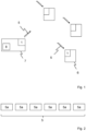
- Fig. 1 shows a communication system according to the invention, in which several terminal devices 6, each with an integrated radio node 1 according to the invention, communicate with a radio node 1 of a data collector 7 via radio.
- the terminal devices 6 can be, for example, consumption measuring devices, such as. B. gas, water, heat or energy meters, sensor units, such as. B. level sensors or temperature measuring devices, or other sensor nodes e.g. B. an LoT (Internet of Things) application.
- the radio node 1 of the data collector 7 is prepared in such a way that it can transmit data 5 to and/or receive from the terminal devices 6 by radio.
- the respective radio node 1 of the terminal devices 6 can also transmit the data 5 to the data collector 7 and/or receive it from the latter.
- the data 5 can be, for example, operating data or program update data or firmware update data or consumption data, which are transmitted from the data collector 7 to the terminal devices 6 and/or vice versa.
- the data collector 7 can use the data 5 e.g. B. received from a higher-level central unit (not shown in the figures), stored in a data memory 8 and then sent to the terminal devices 6. Furthermore, the data collector 7 can receive the data 5 from the terminals 6, store it in the data memory 8 and forward it to the higher-level central unit.
- the data 5 is used as in Fig. 2 shown, transmitted in the form of at least one data packet, preferably a plurality of data packets 5a.
- the data 5 can be sent using a telegram splitting method, preferably via different frequency channels.
- the data 5 can be in the license-free ISM bands, preferably in a frequency band in the range of 865.0 - 868.0 MHz or 868.0 - 868.6 MHz or 869.4 - 869.65 MHz or 902 - 928 MHz be transmitted.
- the radio node can operate with a symbol rate between 2360 symbols/s and 2400 symbols/s, preferably with a symbol rate of 2380.371 symbols/s.
- the data can also be with a coded data rate of less than 100 kbit/s, preferably less than 50 kbit/s, particularly preferably less than 15 kbit/s, most preferably less than 1 kbit/s, and/or with an uncoded data rate less than 35 kbit/s, preferably less than 15 kbit/s, particularly preferably less than 5 kbit/s, very particularly preferably less than 1 kbit/s.
- the reception sensitivity P r of the radio node 1 indicates the minimum reception level at which reception of the data 5 is still possible. If the radio signal power of the data 5 or the signals derived therefrom is below the reception sensitivity P r of the radio node 1, reception is not possible.
- P th is the thermal noise
- B is the bandwidth
- F is the noise figure of radio node 1
- SNR is the signal-to-noise ratio, i.e. the ratio of the useful signal power to the noise power. If the signal-to-noise ratio falls below, reception is no longer possible.
- Thermal noise P th is generated by random free movements of electrons in conductors.
- Fig. 3 shows the temperature dependence of thermal noise. It is clear that thermal noise increases with increasing temperature.
- Fig. 4a shows an example histogram of Received Signal Strength Indication (RSSI) values.
- the RSSI values represent an indicator of the reception field strength of wireless communication applications.
- the reception sensitivity P r of the radio node 1 -137 dBm is merely an example below.
- the reception sensitivity P r is in the Fig. 4a shown as an example by the reception limit 10 shown in dashed lines.
- the radio node 1 can receive all radio signals from the nodes whose power is greater than the reception sensitivity P r of -137 dBm, i.e. powers which are to the right of the reception limit 10 in Fig. 4a lay. Radio signals with a power lower than -137 dBm (to the left of the reception limit 10 in Fig. 4a ), however, can no longer be received by radio node 1.
- the radio node 1 makes it possible to improve the reception sensitivity P r so that signals with a lower power can also be received. For example, it may be possible to reduce the reception sensitivity P r by 3 dBm. Accordingly, the above-mentioned exemplary reception sensitivity P r of -137 dBm is reduced by 3 dBm, so that it is now at -140 dBm, like the dashed line 10 'in Fig. 4a shows. This allows, for example, the radio signals of the nodes to the left of the reception limit 10 in Fig. 4a are received. This will also be in Fig.
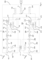
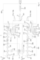
- Fig. 5 shows a simplified schematic representation of the radio node 1 according to the invention according to a first exemplary embodiment.
- the radio node 1 includes two receivers 100, 200, a microcontroller 300 and an oscillator 2, the microcontroller 300 and the oscillator 2 being connected to both receivers 100, 200.
- the microcontroller 300 and the oscillator 2 are arranged on the radio node 1 and are provided together for both receivers 100, 200.
- the two receivers 100, 200 essentially comprise the same hardware components.
- the first receiver 100 receives the data 5 in the form of at least one data packet or a part thereof at a specific data rate by means of an antenna 101.
- the received data 5 is buffered in a buffer 102 and then fed to a mixer 103.
- the mixer 103 is connected to a PLL (Phase Locked Loop) 104, which is connected to the oscillator 2.
- the oscillator 2 oscillates at a specific clock rate, which is communicated to the PLL 104.
- the PLL 104 generates a reception carrier frequency based on the clocking of the oscillator 2, e.g. B. in the range from 800 to 1,000 MHz.
- the signal frequency of the data 5 is adapted to the reception carrier frequency by the mixer 103.
- the data 5 is then fed to a filter 105, which forwards the data 5 to an analog-digital converter (ADC) 106.
- ADC analog-digital converter
- the ADC 106 is also controlled by the oscillator 2.
- the data is decimated using a decimation unit 107 and fed to a mixer 108.
- the mixer 108 also receives a reference frequency from a numerically controlled oscillator (NCO) 109. This adjusts the frequency of the digitized data 5.
- NCO numerically controlled oscillator
- the data 5 is then fed to another filter 110 and then to a demodulator 112.
- the data 5 can be demodulated and further processed by the demodulator 112.
- a switching device 111 is arranged between the filter 110 and the demodulator 112. Using the switching device 111, the data 5 can be diverted from processing so that it is no longer fed to the demodulator 112.
- the branched data 117 is sent to a microcontroller 113 Receivers 100 fed.
- the data 117 is decimated with a decimation unit 114 and synchronized with a synchronization unit 115. With the help of synchronization, the time at which the data 5 arrived at or was received by the receiver 100 can be determined using the data 117.
- the microcontroller 113 can then determine or estimate the phase and/or the group delay of the data 117.
- the second receiver 200 receives the same data 5 as the first microcontroller 100 by means of an antenna 201.
- the hardware processing of the data 5 on the second receiver 200 takes place analogously to the first receiver 100.
- the data 5 is fed to a buffer 202 and then adapted to the reception carrier frequency by means of a mixer 203, which is connected to a PLL 204 connected to the oscillator 2.
- the data 5 are then filtered using a filter 205 and fed to an ADC 206, which is connected to the oscillator 2.
- the data 5 is fed to a further mixer 208, which adjusts the data 5 using a frequency of an NCO 209.
- the data can be fed to either a demodulator 212 or a microcontroller 213 of the receiver 200 by means of a switching device 211.
- the branched data 217 is decimated with a decimation unit 214 and synchronized by means of a synchronization unit 215.
- the microcontroller 213 can then determine or estimate the phase and/or the group delay of the data 217.
- the microcontrollers 113, 213 can estimate or determine the group delay and/or the phase of the branched data 117, 217 and/or a phase shift and/or a group delay difference between the data 117, 217 branched off in the respective receivers 100, 200. This can be done using a brute force process, see comments on Fig. 13 , or by at least one radio signal that is more energetic than the radio signals from other radio nodes or by determining the phase difference, cf. comments on Fig. 14 , happen. The group delay difference and/or the phase shift can be saved.
- the radio signals or data from radio transmitters are used, which are z. B. located near the radio node 1 in its radio system. These have a higher signal power and can therefore be received before the reception sensitivity P r is reduced, as above Figures 4a and 4b explained.
- the group delay difference and/or the phase shift between the branched data 117, 217 can now be determined.
- the group delay and/or the phase of the branched data 117, 217 of the at least two receivers 100, 200 can be adjusted or adjusted to one another.
- the mutually aligned or adapted data 118, 218 are forwarded to the microcontroller 300 and combined or added there by means of a combination unit 301. Since the data 118, 218 are essentially not shifted relative to one another with regard to their group delay and/or phase, they are constructively combined or added. This amplifies the signal of the data 118, 218.
- the white noise generated in the respective receivers 100, 200 by the hardware and/or the signal or data processing and/or by random interference in the transmission channel, on the other hand, is not correlated to one another and is essentially not increased by the combination or addition of the data 118, 218.
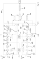
- Fig. 6 shows a second exemplary embodiment of the radio node 1 according to the invention.
- the radio node 1 also includes the receivers 100, 200 and the oscillator 2.
- the microcontroller 300 is missing in the exemplary embodiment.
- the data 5 is essentially as in the first exemplary embodiment Fig. 5 received, processed, branched off and adjusted or adapted to one another by the receivers 100, 200.
- the adjusted or adapted data 118 of the first receiver 100 are now forwarded to the microcontroller 213 of the second receiver 200.
- the data 118, 218 are combined or added using a combination unit 219 and then fed to the decoder 4.
- the combination of the data 118, 218 can also take place on the microcontroller 113 of the first receiver 100.
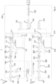
- Fig. 7 shows the radio node 1 according to a third exemplary embodiment.
- the data 5 is essentially as in the first exemplary embodiment Fig. 5 processed.
- a common PLL 3 is provided for both receivers 100, 200 on radio node 1.
- the internal PLLs 104, 204 of the receivers 100, 200 are deactivated. This can ensure that both mixers 103, 203 use the essentially identical reception carrier frequency.
- the respective PLL 104, 204 of the receivers 100, 200 can directly communicate the start phase used to the corresponding microcontrollers 113, 213 via a connection 116, 216.
- the phase of the branched data 117, 217 is known, meaning that it no longer needs to be estimated or determined.
- the processing of the data 5 by the two receivers 100, 200 otherwise corresponds to the first exemplary embodiment Fig. 5 .
- a fifth exemplary embodiment Fig. 9 There is no synchronization of the data in the corresponding microcontroller 113, 213 of the receiver 100, 200 117, 217 provided. Instead, synchronization only takes place after the data 118, 218 have been combined.
- the combined data 11 is according to Fig. 9 a synchronization unit 302 in the microcontroller 300 before they are forwarded to the decoder 4.
- the synchronization after the combination of the data 11 can also be carried out on one of the microcontrollers 113, 213, e.g. B. after a combination of the data 118, 218 by means of the combination unit 219 according to the second exemplary embodiment, cf. Fig. 6 , take place.
- An additional oscillator device 9 can be provided in a sixth exemplary embodiment of the radio node 1.
- the oscillator device 9 is z. B. a low-frequency (LF) oscillator, which is provided together for both receivers 100, 200.
- the oscillator device 9 is connected to the microcontrollers 113, 213 of the two receivers 100, 200 and can wake them up from a rest state when a reception window begins. This makes it possible for the microcontrollers 113, 213 to go into an idle state when they are not needed. This can save additional energy.
- LF low-frequency
- Fig. 11 shows a seventh exemplary embodiment of the radio node 1.
- the data 5 is branched off using the switching device 111, 211 as described above.
- the microcontrollers 113, 213 of the receivers 100, 200 only process one data segment 117a, 217b of the branched data 117, 217.
- the microcontroller 113 of the first receiver 100 only processes one data segment 117a of the branched data 117.
- the microcontroller 213 of the second receiver 200 processes a data segment 217b of the branched data 217.
- the data segments 117b, 217a not processed by the respective microcontrollers 113, 213 are in the Fig. 11 crossed out with an “X”. These data segments 117b, 217a are discarded by the respective microcontroller 113, 213.
- the processed data segments 117a, 217b are then synchronized with the respective synchronization units 115, 215.
- the processed data segments 117a, 217b can be aligned or adapted to one another with regard to their group delay difference and/or their phase shift.
- the aligned or adjusted data segments 118a, 218b can then be linked together or combined in the microcontroller 300.
- the data segments 117a, 217b can be directly connected or combined without any adjustment or adjustment.
- the data segments 117a, 217b and 118a, 218b expediently complement each other, so that the received data 5 can be reconstructed in the form of a data packet or a part thereof by combining the data segments 117a, 217b or 118a, 218b.
- the data 11 are then preferably demodulated using a demodulator 303 and decoded using a decoder 4.
- the radio node 1 can send out data 10 for self-calibration.
- a transmitter 400 uses the antenna 401 to send out the data 10, which is received by the antennas 101, 201 of the receivers 100, 200.
- the group delay difference and/or the phase shift between the two receivers 100, 200 can be estimated or determined in advance and then saved for further use.
- Fig. 13 shows an exemplary flowchart for estimating the group delay difference and/or the phase difference using the brute force method.
- the radio node 1 with the receivers 100, 200 is switched on, step 20.
- a calibration phase is started, step 21, and several data 5 are branched off, step 22.
- step 23 the group delay difference between the branched data 117, 217 is now estimated or determined. Since the hardware of the receivers 100, 200 is known, the range of possible group delay difference is also known. The estimation or determination of the group delay difference can be done in particular with one, e.g. B. double, oversampling can be carried out. For example, with a symbol duration of 10 ⁇ s, a sample is 5 ⁇ s long with double oversampling. Now the branched data 117, 217 can be expanded by a sample, e.g. B. ⁇ 5 ⁇ s. You can then check whether the group delays of the branched data 117, 217 essentially match. The shifting of the samples is repeated until the group delays of the branched data 117, 217 essentially match.
- phase shift of the branched data 117, 217 is then estimated or determined, step 24.
- different numbers of phase shifts must be checked.
- the phases of the branched data 117, 217 are shifted by a certain phase until the phases of the data 217, 218 are adjusted or aligned.
- the estimation or determination of the phase shift can also be carried out before the estimation or determination of the group delay difference.
- the calibration phase ends, step 25, and the reception phase starts, step 26.
- the group delays of the branched data 117, 217 are delayed by the estimated or determined group delay shift, step 27.
- the phase of the branched data 117, 217 is shifted with the estimated or determined phase difference, step 28.
- the phase shifting, step 28, and the delay of the group delay, step 27, can also be carried out in a reverse order.
- the adapted or adjusted data 118, 218 are added or combined, step 29, synchronized, step 30, and decoded, step 31.
- the radio node 1 with the receivers 100, 200 is then switched off, step 32.
- Fig. 14 shows an exemplary flowchart for estimating or determining a group delay difference.
- the receivers 100, 200 are first switched on, steps 40 and 45. Then it is checked whether branched data 117, 217 is present, steps 41 and 46. Phase differences between a sample of the branched data with a previous sample are then checked of the branched data, steps 42 and 47.
- phase differences are then correlated individually, steps 43 and 48. After the correlation, a maximum value search is carried out, steps 44, 49. Maximum values (peaks) can be found, particularly at high SNRs. If the maximum value search is successful for the two correlated data, the times are subtracted from each other and a group delay difference is determined, step 50. The process is then completed, step 51.
- the phase differences are detected by a receiver, e.g. B. from the first receiver 100, to the other receiver, e.g. B. copied to the second receiver 200, step 52.
- the data from the first receiver 100 are shifted by a hypothesis shift, step 53.
- the phase differences are then added, step 54.
- the added phase differences are correlated, step 55, and to maximum values (Peaks) searched, step 56. If a maximum value was found, the hypothesis shift is saved as a group delay difference, step 57, and the process is ended, step 58.
- step 56 If no maximum value is found in step 56, the procedure is repeated from step 53 until a maximum value is found in step 56.
- the radio node 1 therefore has an improved reception sensitivity P r due to the combination of the received data 5, so that lower-energy radio signals and their data 5 can also be received.
Landscapes
- Engineering & Computer Science (AREA)
- Computer Networks & Wireless Communication (AREA)
- Signal Processing (AREA)
- Mobile Radio Communication Systems (AREA)
Applications Claiming Priority (1)
| Application Number | Priority Date | Filing Date | Title |
|---|---|---|---|
| DE102022111541.0A DE102022111541A1 (de) | 2022-05-09 | 2022-05-09 | Funkknoten sowie Kommunikationssystem |
Publications (1)
| Publication Number | Publication Date |
|---|---|
| EP4277155A1 true EP4277155A1 (fr) | 2023-11-15 |
Family
ID=86330101
Family Applications (1)
| Application Number | Title | Priority Date | Filing Date |
|---|---|---|---|
| EP23171733.1A Pending EP4277155A1 (fr) | 2022-05-09 | 2023-05-04 | Noeud radio et système de communication |
Country Status (3)
| Country | Link |
|---|---|
| EP (1) | EP4277155A1 (fr) |
| CN (1) | CN117040557A (fr) |
| DE (1) | DE102022111541A1 (fr) |
Families Citing this family (1)
| Publication number | Priority date | Publication date | Assignee | Title |
|---|---|---|---|---|
| DE102024120680A1 (de) * | 2024-07-19 | 2026-01-22 | Diehl Metering S.A.S. | Funkempfänger, Funksender sowie Funkübertragungssystem |
Citations (7)
| Publication number | Priority date | Publication date | Assignee | Title |
|---|---|---|---|---|
| US20070002961A1 (en) * | 2005-06-29 | 2007-01-04 | Hoctor Ralph T | System and method of communicating signals |
| US20080159123A1 (en) * | 2003-10-08 | 2008-07-03 | Tehrani Ardavan M | Apparatus And Method Of Multiple Antenna Receiver Combining Of High Data Rate Wideband Packetized Wireless Communication Signals |
| US20100075611A1 (en) * | 2008-09-24 | 2010-03-25 | Honeywell International Inc. | Apparatus and method for improved wireless communication reliability and performance in process control systems |
| US20110200144A1 (en) * | 2010-02-18 | 2011-08-18 | Bernd Adler | Apparatus and Method for Antenna Diversity Reception |
| US20120321012A1 (en) * | 2011-06-16 | 2012-12-20 | Javier Elenes | Providing Phase Diversity Combining Of Digital Radio Broadcast Signals |
| US20160191138A1 (en) * | 2014-12-31 | 2016-06-30 | Nxp B.V. | Multiple antenna distributed radio system |
| DE102018003106A1 (de) | 2018-02-28 | 2019-08-29 | Diehl Metering Systems Gmbh | Funkempfänger |
Family Cites Families (1)
| Publication number | Priority date | Publication date | Assignee | Title |
|---|---|---|---|---|
| US8781421B2 (en) | 2012-09-28 | 2014-07-15 | Silicon Laboratories Inc. | Time-domain diversity combining of signals for broadcast receivers |
-
2022
- 2022-05-09 DE DE102022111541.0A patent/DE102022111541A1/de active Pending
-
2023
- 2023-04-28 CN CN202310486323.5A patent/CN117040557A/zh active Pending
- 2023-05-04 EP EP23171733.1A patent/EP4277155A1/fr active Pending
Patent Citations (7)
| Publication number | Priority date | Publication date | Assignee | Title |
|---|---|---|---|---|
| US20080159123A1 (en) * | 2003-10-08 | 2008-07-03 | Tehrani Ardavan M | Apparatus And Method Of Multiple Antenna Receiver Combining Of High Data Rate Wideband Packetized Wireless Communication Signals |
| US20070002961A1 (en) * | 2005-06-29 | 2007-01-04 | Hoctor Ralph T | System and method of communicating signals |
| US20100075611A1 (en) * | 2008-09-24 | 2010-03-25 | Honeywell International Inc. | Apparatus and method for improved wireless communication reliability and performance in process control systems |
| US20110200144A1 (en) * | 2010-02-18 | 2011-08-18 | Bernd Adler | Apparatus and Method for Antenna Diversity Reception |
| US20120321012A1 (en) * | 2011-06-16 | 2012-12-20 | Javier Elenes | Providing Phase Diversity Combining Of Digital Radio Broadcast Signals |
| US20160191138A1 (en) * | 2014-12-31 | 2016-06-30 | Nxp B.V. | Multiple antenna distributed radio system |
| DE102018003106A1 (de) | 2018-02-28 | 2019-08-29 | Diehl Metering Systems Gmbh | Funkempfänger |
Also Published As
| Publication number | Publication date |
|---|---|
| CN117040557A (zh) | 2023-11-10 |
| DE102022111541A1 (de) | 2023-11-09 |
Similar Documents
| Publication | Publication Date | Title |
|---|---|---|
| DE69629724T2 (de) | Kombiniertes gps und kommunikations-system mit geteilten schaltkreisen | |
| DE69533156T2 (de) | Synchrondetektorschaltung und synchronisierungsmethode für einen digitalsignalempfänger | |
| DE69413224T2 (de) | SIGNALISATIONSPAKET FüR KOMMUNIKATIONSSYSTEM MIT MODULIERTER REFERENZ DIE EINEM ZEITABHAENGIGEN GESETZ FOLGT | |
| DE2757171C3 (de) | Verfahren und Anordnung zur Übertragung zweier unterschiedlicher Informationen in einem einzigen Übertragungskanal vorgegebener Bandbreite auf einer Trägerwelle | |
| DE69623337T2 (de) | Zwei-moden funkempfänger zum empfangen von breitband- und schmalbandsignalen | |
| DE69008866T2 (de) | Verfahren und anordnung zur synchronisierung einer basisstation und einer mobilen station bei einem digitalen übertragungssystem. | |
| EP3329621B1 (fr) | Procede de transmission sans fil pour un recepteur simple | |
| DE60223949T2 (de) | Dynamische bandbreitenabschätzung des pilotsignalfilters | |
| DE69936682T2 (de) | Basistation und Funkübertragungsverfahren mit Empfängsdiversität | |
| DE2808846B2 (de) | Funkverbindungssystem unter Ausnutzung troposphärischer Streuung | |
| DE3302828A1 (de) | Empfangsgeraet | |
| DE102004059957A1 (de) | Synchronisationsvorrichtung und Vorrichtung zum Erzeugen eines Synchronisationssignals | |
| DE10345959B4 (de) | Betriebssituationsabhängige Ermittlung und Selektion der Übertragungspfade für die Einrichtung von Rake-Fingern von Rake-Empfängereinheiten in Mobilkommunikations-Endgeräten | |
| DE102018206159B3 (de) | Paket-Detektor/Decoder für ein Funkübertragungssystem | |
| EP1708387B1 (fr) | Appareil récepteur avec diversité d'antennes pour des signaux radio numériques modulés en MPSK pour des voitures | |
| DE3789250T2 (de) | Verfahren und Einrichtung zur Übertragung von Bilddaten in einem Satellitensystem. | |
| EP4277155A1 (fr) | Noeud radio et système de communication | |
| DE69817534T2 (de) | Demodulation mit aparten zweigen für phase sowie für amplitude | |
| EP1396089B1 (fr) | Procede de compensation d'une interference echelonnee de courant continu dans un signal de bande de base numerique d'un recepteur radio homodyne | |
| DE60207866T2 (de) | Verfahren und system zum empfang eines mehrträgersignals mit mehrwegediversity, und entsprechender empfänger | |
| DE102019206105B3 (de) | Empfängerseitige ermittlung eines zeitpunkts eines senderseitigen ereignisses | |
| DE3035759C2 (fr) | ||
| WO1995034961A1 (fr) | Procede de synchronisation de frequences de porteuses dans un reseau radio-mobile | |
| DE10250861B4 (de) | Verfahren und Vorrichtungen zur Detektion des TX-Diversity-Modes für Mobilfunkempfänger | |
| EP4654681A1 (fr) | Procédé de fonctionnement d'un récepteur radio autonome en énergie d'une passerelle |
Legal Events
| Date | Code | Title | Description |
|---|---|---|---|
| PUAI | Public reference made under article 153(3) epc to a published international application that has entered the european phase |
Free format text: ORIGINAL CODE: 0009012 |
|
| STAA | Information on the status of an ep patent application or granted ep patent |
Free format text: STATUS: THE APPLICATION HAS BEEN PUBLISHED |
|
| AK | Designated contracting states |
Kind code of ref document: A1 Designated state(s): AL AT BE BG CH CY CZ DE DK EE ES FI FR GB GR HR HU IE IS IT LI LT LU LV MC ME MK MT NL NO PL PT RO RS SE SI SK SM TR |
|
| STAA | Information on the status of an ep patent application or granted ep patent |
Free format text: STATUS: REQUEST FOR EXAMINATION WAS MADE |
|
| 17P | Request for examination filed |
Effective date: 20240304 |
|
| RBV | Designated contracting states (corrected) |
Designated state(s): AL AT BE BG CH CY CZ DE DK EE ES FI FR GB GR HR HU IE IS IT LI LT LU LV MC ME MK MT NL NO PL PT RO RS SE SI SK SM TR |
|
| STAA | Information on the status of an ep patent application or granted ep patent |
Free format text: STATUS: EXAMINATION IS IN PROGRESS |
|
| 17Q | First examination report despatched |
Effective date: 20251027 |