EP4277191A2 - Port de signal de référence de suivi de phase ou partage de configuration sur de multiples canaux de liaison descendante physiques de multiples points de réception de transmission - Google Patents
Port de signal de référence de suivi de phase ou partage de configuration sur de multiples canaux de liaison descendante physiques de multiples points de réception de transmission Download PDFInfo
- Publication number
- EP4277191A2 EP4277191A2 EP23195697.0A EP23195697A EP4277191A2 EP 4277191 A2 EP4277191 A2 EP 4277191A2 EP 23195697 A EP23195697 A EP 23195697A EP 4277191 A2 EP4277191 A2 EP 4277191A2
- Authority
- EP
- European Patent Office
- Prior art keywords
- ptrs
- pdschs
- shared
- aspects
- dci
- Prior art date
- Legal status (The legal status is an assumption and is not a legal conclusion. Google has not performed a legal analysis and makes no representation as to the accuracy of the status listed.)
- Granted
Links
Images


Classifications
-
- H—ELECTRICITY
- H04—ELECTRIC COMMUNICATION TECHNIQUE
- H04L—TRANSMISSION OF DIGITAL INFORMATION, e.g. TELEGRAPHIC COMMUNICATION
- H04L5/00—Arrangements affording multiple use of the transmission path
- H04L5/0001—Arrangements for dividing the transmission path
- H04L5/0003—Two-dimensional division
- H04L5/0005—Time-frequency
- H04L5/0007—Time-frequency the frequencies being orthogonal, e.g. OFDM(A) or DMT
- H04L5/001—Time-frequency the frequencies being orthogonal, e.g. OFDM(A) or DMT the frequencies being arranged in component carriers
-
- H—ELECTRICITY
- H04—ELECTRIC COMMUNICATION TECHNIQUE
- H04L—TRANSMISSION OF DIGITAL INFORMATION, e.g. TELEGRAPHIC COMMUNICATION
- H04L27/00—Modulated-carrier systems
- H04L27/26—Systems using multi-frequency codes
- H04L27/2601—Multicarrier modulation systems
- H04L27/2602—Signal structure
- H04L27/261—Details of reference signals
- H04L27/2613—Structure of the reference signals
-
- H—ELECTRICITY
- H04—ELECTRIC COMMUNICATION TECHNIQUE
- H04L—TRANSMISSION OF DIGITAL INFORMATION, e.g. TELEGRAPHIC COMMUNICATION
- H04L27/00—Modulated-carrier systems
- H04L27/26—Systems using multi-frequency codes
- H04L27/2601—Multicarrier modulation systems
- H04L27/2647—Arrangements specific to the receiver only
- H04L27/2655—Synchronisation arrangements
- H04L27/2657—Carrier synchronisation
-
- H—ELECTRICITY
- H04—ELECTRIC COMMUNICATION TECHNIQUE
- H04L—TRANSMISSION OF DIGITAL INFORMATION, e.g. TELEGRAPHIC COMMUNICATION
- H04L27/00—Modulated-carrier systems
- H04L27/26—Systems using multi-frequency codes
- H04L27/2601—Multicarrier modulation systems
- H04L27/2647—Arrangements specific to the receiver only
- H04L27/2655—Synchronisation arrangements
- H04L27/2668—Details of algorithms
- H04L27/2673—Details of algorithms characterised by synchronisation parameters
- H04L27/2675—Pilot or known symbols
-
- H—ELECTRICITY
- H04—ELECTRIC COMMUNICATION TECHNIQUE
- H04L—TRANSMISSION OF DIGITAL INFORMATION, e.g. TELEGRAPHIC COMMUNICATION
- H04L5/00—Arrangements affording multiple use of the transmission path
- H04L5/003—Arrangements for allocating sub-channels of the transmission path
- H04L5/0032—Distributed allocation, i.e. involving a plurality of allocating devices, each making partial allocation
- H04L5/0035—Resource allocation in a cooperative multipoint environment
-
- H—ELECTRICITY
- H04—ELECTRIC COMMUNICATION TECHNIQUE
- H04L—TRANSMISSION OF DIGITAL INFORMATION, e.g. TELEGRAPHIC COMMUNICATION
- H04L5/00—Arrangements affording multiple use of the transmission path
- H04L5/003—Arrangements for allocating sub-channels of the transmission path
- H04L5/0044—Allocation of payload; Allocation of data channels, e.g. PDSCH or PUSCH
-
- H—ELECTRICITY
- H04—ELECTRIC COMMUNICATION TECHNIQUE
- H04L—TRANSMISSION OF DIGITAL INFORMATION, e.g. TELEGRAPHIC COMMUNICATION
- H04L5/00—Arrangements affording multiple use of the transmission path
- H04L5/003—Arrangements for allocating sub-channels of the transmission path
- H04L5/0048—Allocation of pilot signals, i.e. of signals known to the receiver
- H04L5/005—Allocation of pilot signals, i.e. of signals known to the receiver of common pilots, i.e. pilots destined for multiple users or terminals
-
- H—ELECTRICITY
- H04—ELECTRIC COMMUNICATION TECHNIQUE
- H04L—TRANSMISSION OF DIGITAL INFORMATION, e.g. TELEGRAPHIC COMMUNICATION
- H04L5/00—Arrangements affording multiple use of the transmission path
- H04L5/003—Arrangements for allocating sub-channels of the transmission path
- H04L5/0048—Allocation of pilot signals, i.e. of signals known to the receiver
- H04L5/0051—Allocation of pilot signals, i.e. of signals known to the receiver of dedicated pilots, i.e. pilots destined for a single user or terminal
-
- H—ELECTRICITY
- H04—ELECTRIC COMMUNICATION TECHNIQUE
- H04L—TRANSMISSION OF DIGITAL INFORMATION, e.g. TELEGRAPHIC COMMUNICATION
- H04L5/00—Arrangements affording multiple use of the transmission path
- H04L5/003—Arrangements for allocating sub-channels of the transmission path
- H04L5/0053—Allocation of signalling, i.e. of overhead other than pilot signals
-
- H—ELECTRICITY
- H04—ELECTRIC COMMUNICATION TECHNIQUE
- H04L—TRANSMISSION OF DIGITAL INFORMATION, e.g. TELEGRAPHIC COMMUNICATION
- H04L5/00—Arrangements affording multiple use of the transmission path
- H04L5/0091—Signalling for the administration of the divided path, e.g. signalling of configuration information
-
- H—ELECTRICITY
- H04—ELECTRIC COMMUNICATION TECHNIQUE
- H04W—WIRELESS COMMUNICATION NETWORKS
- H04W72/00—Local resource management
- H04W72/20—Control channels or signalling for resource management
- H04W72/23—Control channels or signalling for resource management in the downlink direction of a wireless link, i.e. towards a terminal
-
- H—ELECTRICITY
- H04—ELECTRIC COMMUNICATION TECHNIQUE
- H04W—WIRELESS COMMUNICATION NETWORKS
- H04W76/00—Connection management
- H04W76/20—Manipulation of established connections
- H04W76/27—Transitions between radio resource control [RRC] states
Definitions
- aspects of the present disclosure generally relate to wireless communication and to techniques and apparatuses for phase tracking reference signal (PTRS) port or configuration sharing across multiple physical downlink channels of multiple transmit receive points (TRPs).
- PTRS phase tracking reference signal
- Wireless communication systems are widely deployed to provide various telecommunication services such as telephony, video, data, messaging, and broadcasts.
- Typical wireless communication systems may employ multiple-access technologies capable of supporting communication with multiple users by sharing available system resources (e.g., bandwidth, transmit power, and/or the like).
- multiple-access technologies include code division multiple access (CDMA) systems, time division multiple access (TDMA) systems, frequency-division multiple access (FDMA) systems, orthogonal frequency-division multiple access (OFDMA) systems, single-carrier frequency-division multiple access (SC-FDMA) systems, time division synchronous code division multiple access (TD-SCDMA) systems, and Long Term Evolution (LTE).
- LTE/LTE-Advanced is a set of enhancements to the Universal Mobile Telecommunications System (UMTS) mobile standard promulgated by the Third Generation Partnership Project (3GPP).
- UMTS Universal Mobile Telecommunications System
- a wireless communication network may include a number of base stations (BSs) that can support communication for a number of user equipment (UEs).
- a user equipment (UE) may communicate with a base station (BS) via the downlink and uplink.
- the downlink (or forward link) refers to the communication link from the BS to the UE
- the uplink (or reverse link) refers to the communication link from the UE to the BS.
- a BS may be referred to as a Node B, a gNB, an access point (AP), a radio head, a transmit receive point (TRP), a New Radio (NR) BS, a 5G Node B, and/or the like.
- New Radio which may also be referred to as 5G, is a set of enhancements to the LTE mobile standard promulgated by the Third Generation Partnership Project (3GPP).
- 3GPP Third Generation Partnership Project
- NR is designed to better support mobile broadband Internet access by improving spectral efficiency, lowering costs, improving services, making use of new spectrum, and better integrating with other open standards using orthogonal frequency division multiplexing (OFDM) with a cyclic prefix (CP) (CP-OFDM) on the downlink (DL), using CP-OFDM and/or SC-FDM (e.g., also known as discrete Fourier transform spread OFDM (DFT-s-OFDM)) on the uplink (UL), as well as supporting beamforming, multiple-input multiple-output (MIMO) antenna technology, and carrier aggregation.
- OFDM orthogonal frequency division multiplexing
- SC-FDM e.g., also known as discrete Fourier transform spread OFDM (DFT-s-OFDM)
- MIMO multiple-input multiple-output
- a method of wireless communication may include determining that a phase tracking reference signal (PTRS) port is to be shared among a plurality of physical downlink shared channels (PDSCHs) transmitted by a plurality of transmit receive points (TRPs); receiving PTRS pilot signals on one or more PDSCHs of the plurality of PDSCHs; and using the PTRS pilot signals for phase tracking estimation for the plurality of PDSCHs based at least in part on the determination that the PTRS port is to be shared among the plurality of PDSCHs.
- PTRS phase tracking reference signal
- a UE for wireless communication may include memory and one or more processors operatively coupled to the memory.
- the memory and the one or more processors may be configured to determine that a PTRS port is to be shared among a plurality of PDSCHs transmitted by a plurality of TRPs; receive PTRS pilot signals on one or more PDSCHs of the plurality of PDSCHs; and use the PTRS pilot signals for phase tracking estimation for the plurality of PDSCHs based at least in part on the determination that the PTRS port is to be shared among the plurality of PDSCHs.
- a non-transitory computer-readable medium may store one or more instructions for wireless communication.
- the one or more instructions when executed by one or more processors of a UE, may cause the one or more processors to determine that a PTRS port is to be shared among a plurality of PDSCHs transmitted by a plurality of TRPs; receive PTRS pilot signals on one or more PDSCHs of the plurality of PDSCHs; and use the PTRS pilot signals for phase tracking estimation for the plurality of PDSCHs based at least in part on the determination that the PTRS port is to be shared among the plurality of PDSCHs.
- an apparatus for wireless communication may include means for determining that a PTRS port is to be shared among a plurality of PDSCHs transmitted by a plurality of TRPs; means for receiving PTRS pilot signals on one or more PDSCHs of the plurality of PDSCHs; and means for using the PTRS pilot signals for phase tracking estimation for the plurality of PDSCHs based at least in part on the determination that the PTRS port is to be shared among the plurality of PDSCHs.
- a method of wireless communication may include determining that the UE is to communicate with multiple TRPs using a specific multi-TRP mode, wherein the specific multi-TRP mode indicates a number of downlink control information (DCI) communications to be used for scheduling and a number of PDSCHs to be scheduled by the number of DCI communications, wherein the number of PDSCHs are transmitted by the multiple TRPs; determining whether to use a shared PTRS configuration across the number of PDSCHs or separate PTRS configurations for the number of PDSCHs based at least in part on the specific multi TRP mode; and selectively using the shared PTRS configuration or the separate PTRS configurations for phase tracking estimation on the number of PDSCHs based at least in part on the determination of whether to use the shared PTRS configuration or the separate PTRS configurations.
- DCI downlink control information
- a UE for wireless communication may include memory and one or more processors operatively coupled to the memory.
- the memory and the one or more processors may be configured to determine that the UE is to communicate with multiple TRPs using a specific multi-TRP mode, wherein the specific multi-TRP mode indicates a number of DCI communications to be used for scheduling and a number of PDSCHs to be scheduled by the number of DCI communications, wherein the number of PDSCHs are transmitted by the multiple TRPs; determine whether to use a shared PTRS configuration across the number of PDSCHs or separate PTRS configurations for the number of PDSCHs based at least in part on the specific multi TRP mode; and selectively use the shared PTRS configuration or the separate PTRS configurations for phase tracking estimation on the number of PDSCHs based at least in part on the determination of whether to use the shared PTRS configuration or the separate PTRS configurations.
- a non-transitory computer-readable medium may store one or more instructions for wireless communication.
- the one or more instructions when executed by one or more processors of a UE, may cause the one or more processors to determine that the UE is to communicate with multiple TRPs using a specific multi-TRP mode, wherein the specific multi-TRP mode indicates a number of DCI communications to be used for scheduling and a number of PDSCHs to be scheduled by the number of DCI communications, wherein the number of PDSCHs are transmitted by the multiple TRPs; determine whether to use a shared PTRS configuration across the number of PDSCHs or separate PTRS configurations for the number of PDSCHs based at least in part on the specific multi TRP mode; and selectively use the shared PTRS configuration or the separate PTRS configurations for phase tracking estimation on the number of PDSCHs based at least in part on the determination of whether to use the shared PTRS configuration or the separate PTRS configurations.
- an apparatus for wireless communication may include means for determining that the apparatus is to communicate with multiple TRPs using a specific multi-TRP mode, wherein the specific multi-TRP mode indicates a number of DCI communications to be used for scheduling and a number of PDSCHs to be scheduled by the number of DCI communications, wherein the number of PDSCHs are transmitted by the multiple TRPs; means for determining whether to use a shared PTRS configuration across the number of PDSCHs or separate PTRS configurations for the number of PDSCHs based at least in part on the specific multi TRP mode; and means for selectively using the shared PTRS configuration or the separate PTRS configurations for phase tracking estimation on the number of PDSCHs based at least in part on the determination of whether to use the shared PTRS configuration or the separate PTRS configurations.
- aspects generally include a method, apparatus, system, computer program product, non-transitory computer-readable medium, user equipment, base station, wireless communication device, TRP, and processing system as substantially described herein with reference to and as illustrated by the accompanying drawings and specification.
- Fig. 1 is a diagram illustrating a network 100 in which aspects of the present disclosure may be practiced.
- the network 100 may be an LTE network or some other wireless network, such as a 5G or NR network.
- Wireless network 100 may include a number of BSs 110 (shown as BS 110a, BS 110b, BS 110c, and BS 110d) and other network entities.
- a BS is an entity that communicates with user equipment (UEs) and may also be referred to as a base station, a NR BS, a Node B, a gNB, a 5G node B (NB), an access point, a transmit receive point (TRP), and/or the like.
- Each BS may provide communication coverage for a particular geographic area.
- the term "cell" can refer to a coverage area of a BS and/or a BS subsystem serving this coverage area, depending on the context in which the term is used.
- a BS may provide communication coverage for a macro cell, a pico cell, a femto cell, and/or another type of cell.
- a macro cell may cover a relatively large geographic area (e.g., several kilometers in radius) and may allow unrestricted access by UEs with service subscription.
- a pico cell may cover a relatively small geographic area and may allow unrestricted access by UEs with service subscription.
- a femto cell may cover a relatively small geographic area (e.g., a home) and may allow restricted access by UEs having association with the femto cell (e.g., UEs in a closed subscriber group (CSG)).
- a BS for a macro cell may be referred to as a macro BS.
- a BS for a pico cell may be referred to as a pico BS.
- a BS for a femto cell may be referred to as a femto BS or a home BS.
- a BS 110a may be a macro BS for a macro cell 102a
- a BS 110b may be a pico BS for a pico cell 102b
- a BS 110c may be a femto BS for a femto cell 102c.
- a BS may support one or multiple (e.g., three) cells.
- the terms "eNB”, “base station”, “NR BS”, “gNB”, “TRP”, “AP”, “node B", “5G NB”, and “cell” may be used interchangeably herein.
- a cell may not necessarily be stationary, and the geographic area of the cell may move according to the location of a mobile BS.
- the BSs may be interconnected to one another and/or to one or more other BSs or network nodes (not shown) in the access network 100 through various types of backhaul interfaces such as a direct physical connection, a virtual network, and/or the like using any suitable transport network.
- Wireless network 100 may also include relay stations.
- a relay station is an entity that can receive a transmission of data from an upstream station (e.g., a BS or a UE) and send a transmission of the data to a downstream station (e.g., a UE or a BS).
- a relay station may also be a UE that can relay transmissions for other UEs.
- a relay station 110d may communicate with macro BS 110a and a UE 120d in order to facilitate communication between BS 110a and UE 120d.
- a relay station may also be referred to as a relay BS, a relay base station, a relay, and/or the like.
- Wireless network 100 may be a heterogeneous network that includes BSs of different types, e.g., macro BSs, pico BSs, femto BSs, relay BSs, and/or the like. These different types of BSs may have different transmit power levels, different coverage areas, and different impacts on interference in wireless network 100.
- macro BSs may have a high transmit power level (e.g., 5 to 40 Watts) whereas pico BSs, femto BSs, and relay BSs may have lower transmit power levels (e.g., 0.1 to 2 Watts).
- a network controller 130 may couple to a set of BSs and may provide coordination and control for these BSs.
- Network controller 130 may communicate with the BSs via a backhaul.
- the BSs may also communicate with one another, e.g., directly or indirectly via a wireless or wireline backhaul.
- UEs 120 may be dispersed throughout wireless network 100, and each UE may be stationary or mobile.
- a UE may also be referred to as an access terminal, a terminal, a mobile station, a subscriber unit, a station, and/or the like.
- a UE may be a cellular phone (e.g., a smart phone), a personal digital assistant (PDA), a wireless modem, a wireless communication device, a handheld device, a laptop computer, a cordless phone, a wireless local loop (WLL) station, a tablet, a camera, a gaming device, a netbook, a smartbook, an ultrabook, a medical device or medical equipment, biometric sensors/devices, wearable devices (smart watches, smart clothing, smart glasses, smart wrist bands, smart jewelry (e.g., smart ring, smart bracelet)), an entertainment device (e.g., a music or video device, or a satellite radio), a vehicular component or sensor, smart meters/sensors, industrial manufacturing equipment, a global positioning system device, or any other suitable device that is configured to communicate via a wireless or wired medium.
- a cellular phone e.g., a smart phone
- PDA personal digital assistant
- WLL wireless local loop
- MTC and eMTC UEs include, for example, robots, drones, remote devices, sensors, meters, monitors, location tags, and/or the like, that may communicate with a base station, another device (e.g., remote device), or some other entity.
- a wireless node may provide, for example, connectivity for or to a network (e.g., a wide area network such as Internet or a cellular network) via a wired or wireless communication link.
- Some UEs may be considered Internet-of Things (IoT) devices, and/or may be implemented as NB-IoT (narrowband internet of things) devices.
- Some UEs may be considered a Customer Premises Equipment (CPE).
- UE 120 may be included inside a housing that houses components of UE 120, such as processor components, memory components, and/or the like.
- any number of wireless networks may be deployed in a given geographic area.
- Each wireless network may support a particular RAT and may operate on one or more frequencies.
- a RAT may also be referred to as a radio technology, an air interface, and/or the like.
- a frequency may also be referred to as a carrier, a frequency channel, and/or the like.
- Each frequency may support a single RAT in a given geographic area in order to avoid interference between wireless networks of different RATs.
- NR or 5G RAT networks may be deployed.
- two or more UEs 120 may communicate directly using one or more sidelink channels (e.g., without using a base station 110 as an intermediary to communicate with one another).
- the UEs 120 may communicate using peer-to-peer (P2P) communications, device-to-device (D2D) communications, a vehicle-to-everything (V2X) protocol (e.g., which may include a vehicle-to-vehicle (V2V) protocol, a vehicle-to-infrastructure (V2I) protocol, and/or the like), a mesh network, and/or the like).
- V2X vehicle-to-everything
- the UE 120 may perform scheduling operations, resource selection operations, and/or other operations described elsewhere herein as being performed by the base station 110.
- Fig. 1 is provided merely as an example. Other examples may differ from what is described with regard to Fig. 1 .
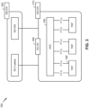
- Fig. 2 shows a block diagram of a design 200 of base station 110 and UE 120, which may be one of the base stations and one of the UEs in Fig. 1 .
- Base station 110 may be equipped with T antennas 234a through 234t
- UE 120 may be equipped with R antennas 252a through 252r, where in general T ⁇ 1 and R ⁇ 1.
- a transmit processor 220 may receive data from a data source 212 for one or more UEs, select one or more modulation and coding schemes (MCS) for each UE based at least in part on channel quality indicators (CQIs) received from the UE, process (e.g., encode and modulate) the data for each UE based at least in part on the MCS(s) selected for the UE, and provide data symbols for all UEs. Transmit processor 220 may also process system information (e.g., for semi-static resource partitioning information (SRPI) and/or the like) and control information (e.g., CQI requests, grants, upper layer signaling, and/or the like) and provide overhead symbols and control symbols.
- MCS modulation and coding schemes
- CQIs channel quality indicators
- Transmit processor 220 may also process system information (e.g., for semi-static resource partitioning information (SRPI) and/or the like) and control information (e.g., CQI requests, grants, upper layer signal
- Transmit processor 220 may also generate reference symbols for reference signals (e.g., the cell-specific reference signal (CRS)) and synchronization signals (e.g., the primary synchronization signal (PSS) and secondary synchronization signal (SSS)).
- a transmit (TX) multiple-input multiple-output (MIMO) processor 230 may perform spatial processing (e.g., precoding) on the data symbols, the control symbols, the overhead symbols, and/or the reference symbols, if applicable, and may provide T output symbol streams to T modulators (MODs) 232a through 232t. Each modulator 232 may process a respective output symbol stream (e.g., for OFDM and/or the like) to obtain an output sample stream.
- Each modulator 232 may further process (e.g., convert to analog, amplify, filter, and upconvert) the output sample stream to obtain a downlink signal.
- T downlink signals from modulators 232a through 232t may be transmitted via T antennas 234a through 234t, respectively.
- the synchronization signals can be generated with location encoding to convey additional information.
- antennas 252a through 252r may receive the downlink signals from base station 110 and/or other base stations and may provide received signals to demodulators (DEMODs) 254a through 254r, respectively.
- Each demodulator 254 may condition (e.g., filter, amplify, downconvert, and digitize) a received signal to obtain input samples.
- Each demodulator 254 may further process the input samples (e.g., for OFDM and/or the like) to obtain received symbols.
- a MIMO detector 256 may obtain received symbols from all R demodulators 254a through 254r, perform MIMO detection on the received symbols if applicable, and provide detected symbols.
- a receive processor 258 may process (e.g., demodulate and decode) the detected symbols, provide decoded data for UE 120 to a data sink 260, and provide decoded control information and system information to a controller/processor 280.
- a channel processor may determine reference signal received power (RSRP), received signal strength indicator (RSSI), reference signal received quality (RSRQ), channel quality indicator (CQI), and/or the like.
- RSRP reference signal received power
- RSSI received signal strength indicator
- RSRQ reference signal received quality indicator
- CQI channel quality indicator
- one or more components of UE 120 may be included in a housing.
- a transmit processor 264 may receive and process data from a data source 262 and control information (e.g., for reports comprising RSRP, RSSI, RSRQ, CQI, and/or the like) from controller/processor 280. Transmit processor 264 may also generate reference symbols for one or more reference signals. The symbols from transmit processor 264 may be precoded by a TX MIMO processor 266 if applicable, further processed by modulators 254a through 254r (e.g., for DFT-s-OFDM, CP-OFDM, and/or the like), and transmitted to base station 110.
- control information e.g., for reports comprising RSRP, RSSI, RSRQ, CQI, and/or the like
- Transmit processor 264 may also generate reference symbols for one or more reference signals.
- the symbols from transmit processor 264 may be precoded by a TX MIMO processor 266 if applicable, further processed by modulators 254a through 254r (e.g., for DFT-
- the uplink signals from UE 120 and other UEs may be received by antennas 234, processed by demodulators 232, detected by a MIMO detector 236 if applicable, and further processed by a receive processor 238 to obtain decoded data and control information sent by UE 120.
- Receive processor 238 may provide the decoded data to a data sink 239 and the decoded control information to controller/processor 240.
- Base station 110 may include communication unit 244 and communicate to network controller 130 via communication unit 244.
- Network controller 130 may include communication unit 294, controller/processor 290, and memory 292.
- Controller/processor 240 of base station 110, controller/processor 280 of UE 120, and/or any other component(s) of Fig. 2 may perform one or more techniques associated with phase tracking reference signal (PTRS) port or configuration sharing across multiple physical downlink channels of multiple transmit receive points (TRPs), as described in more detail elsewhere herein.
- controller/processor 240 of base station 110, controller/processor 280 of UE 120, and/or any other component(s) of Fig. 2 may perform or direct operations of, for example, process 1100 of Fig. 11 , process 1200 of Fig. 12 , and/or other processes as described herein.
- Memories 242 and 282 may store data and program codes for base station 110 and UE 120, respectively.
- a scheduler 246 may schedule UEs for data transmission on the downlink and/or uplink.
- the UE 120 may include means for determining that a PTRS port is to be shared among a plurality of physical downlink shared channels (PDSCHs) transmitted by a plurality of TRPs; means for receiving PTRS pilot signals on one or more PDSCHs of the plurality of PDSCHs; means for using the PTRS pilot signals for phase tracking estimation for the plurality of PDSCHs based at least in part on the determination that the PTRS port is to be shared among the plurality of PDSCHs; and/or the like.
- PDSCHs physical downlink shared channels
- the UE 120 may include means for determining that the UE 120 is to communicate with multiple TRPs using a specific multi-TRP mode, wherein the specific multi-TRP mode indicates a number of downlink control information (DCI) communications to be used for scheduling and a number of PDSCHs to be scheduled by the number of DCI communications, wherein the number of PDSCHs are transmitted by the multiple TRPs; means for determining whether to use a shared PTRS configuration across the number of PDSCHs or separate PTRS configurations for the number of PDSCHs based at least in part on the specific multi TRP mode; means for selectively using the shared PTRS configuration or the separate PTRS configurations for phase tracking estimation on the number of PDSCHs based at least in part on the determination of whether to use the shared PTRS configuration or the separate PTRS configurations; and/or the like.
- such means may include one or more components of UE 120 described in connection with Fig. 2 .
- Fig. 2 is provided merely as an example. Other examples may differ from what is described with regard to Fig. 2 .
- Fig. 3 illustrates an example logical architecture of a distributed RAN 300, according to various aspects of the present disclosure.
- a 5G access node 306 may include an access node controller (ANC) 302.
- the ANC 302 may be a central unit (CU) of the distributed RAN 300.
- the backhaul interface to the next generation core network (NG-CN) 304 may terminate at the ANC 302.
- the backhaul interface to neighboring next generation access nodes (NG-ANs) may terminate at the ANC 302.
- the ANC 302 may include one or more TRPs 308 (which may also be referred to as BSs, NR BSs, Node Bs, 5G NBs, APs, gNB, or some other term).
- TRP may be used interchangeably with "cell.”
- multiple TRPs 308 may be included in a single base station 110. Additionally, or alternatively, different TRPs 308 may be included in different base stations 110.
- a TRP 308 may be a distributed unit (DU).
- a TRP 308 may be connected to a single ANC 502 or multiple ANCs 302.
- a TRP 308 may be connected to more than one ANC 302.
- a TRP 308 may include one or more antenna ports.
- the TRPs 308 may be configured to individually (e.g., dynamic selection) or jointly (e.g., joint transmission) serve traffic to a UE 120.
- the local architecture of RAN 300 may be used to illustrate fronthaul definition.
- the architecture may be defined to support fronthauling solutions across different deployment types.
- the architecture may be based at least in part on transmit network capabilities (e.g., bandwidth, latency, and/or jitter).
- the architecture may share features and/or components with LTE.
- the next generation AN (NG-AN) 310 may support dual connectivity with NR.
- the NG-AN may share a common fronthaul for LTE and NR.
- the architecture may enable coordination between and among TRPs 308. For example, coordination may be preset within a TRP 308 and/or across TRPs 308 via the ANC 302. According to aspects, no inter-TRP interface may be needed/present.
- a dynamic configuration of split logical functions may be present within the architecture of RAN 300.
- the packet data convergence protocol (PDCP), radio link control (RLC), or medium access control (MAC) protocol may be adaptably placed at the ANC 302 or TRP 308.
- a base station 110 may include a central unit (CU) (e.g., ANC 302) and/or one or more distributed units (e.g., one or more TRPs 308).
- CU central unit
- distributed units e.g., one or more TRPs 308.
- Fig. 3 is provided merely as an example. Other examples may differ from what is described with regard to Fig. 3 .
- Fig. 4 illustrates an example physical architecture of a distributed RAN 400, according to various aspects of the present disclosure.
- a centralized core network unit (C-CU) 402 may host core network functions.
- the C-CU 402 may be centrally deployed. Functionality of the C-CU may be offloaded (e.g., to advanced wireless services (AWS)), in an effort to handle peak capacity.
- a centralized RAN unit (C-RU) 404 may host one or more ANC functions.
- the C-RU 404 may host core network functions locally.
- the C-RU 404 may have distributed deployment.
- the C-RU 404 may be closer to the network edge.
- a distributed unit (DU) 406 may host one or more TRPs 308. The DU 406 may be located at edges of the network with radio frequency (RF) functionality.
- RF radio frequency
- Fig. 4 is provided merely as an example. Other examples may differ from what is described with regard to Fig. 4 .
- Fig. 5 is a diagram illustrating an example 500 of multi-TRP communication, in accordance with various aspects of the present disclosure.
- multiple TRPs 308 may communicate with the same UE 120 in a coordinated manner (e.g., using coordinated multipoint transmissions and/or the like) to improve reliability, increase throughput, and/or the like.
- the TRPs 308 may coordinate such communications via a backhaul, which may have a smaller delay and/or higher capacity when the TRPs 308 are co-located at the same base station 110 (e.g., different antenna arrays of the same base station 110), or may have a larger delay and/or lower capacity when the TRPs 308 are located at different base stations 110.
- multiple TRPs 308 may jointly transmit one or more physical downlink control channels (PDCCHs), physical downlink shared channels (PDSCHs), and/or reference signals to the same UE 120.
- the UE 120 may receive communications via multiple PDSCHs of the multiple TRPs 308, shown as PDSCH A from TRP A and PDSCH B from TRP B.
- the number of PDSCHs received by the UE 120 need not be equal to the number of TRPs 308 communicating with the UE 120 (e.g., the TRPs 308 and PDSCHs need not have a one-to-one correspondence).
- TRPs 308 may transmit reference signals to the UE 120, such as a phase tracking reference signal (PTRS) used to correct phase noise, especially for millimeter wave communications.
- PTRS phase tracking reference signal
- the PTRS is described in more detail below in connection with Fig. 6 .
- Fig. 5 is provided merely as an example. Other examples may differ from what is described with regard to Fig. 5 .
- Fig. 6 is a diagram illustrating an example 600 of an assignment of PTRSs and other signals and channels to resource elements, in accordance with various aspects of the present disclosure.
- Fig. 6 illustrates PTRS pilot signals (also referred to as PTRS pilot tones) for a CP-OFDM communication system.
- PTRS pilot signals may be continuous (as illustrated) or discontinuous in the time domain.
- the PTRS signals may occupy one tone or several tones, based at least in part on a scheduled bandwidth, a modulation and coding scheme (MCS), a signal-to-noise ratio (SNR), an interference level, a port mapping, and/or other attributes that may impact the received signal quality of communication signals.
- MCS modulation and coding scheme
- SNR signal-to-noise ratio
- PTRS pilot signals may be used by the UE 120 to correct oscillator phase noise, especially for millimeter wave communications.
- a higher SNR in the PTRS pilot signals may provide a more accurate phase error estimation.
- the PTRS pilot signals may be located in the tones with good channel conditions, high SNR, and/or high signal-to-interference-plus-noise ratio (SINR), which may result in more accurate phase tracking at the UE 120.
- SINR signal-to-interference-plus-noise ratio
- Increasing the number of PTRS pilot signals may provide more accurate phase error estimation. For example, an increased number of PTRS pilot signals may allow for thermal noise to be averaged out over the larger number of PTRS pilot signals. Additionally, an increased number of PTRS pilot signals may allow for frequency diversity to be exploited.
- UEs 120 with a large scheduled bandwidth may use a sparser PTRS frequency domain pattern.
- UEs 120 with a small scheduled bandwidth may use a denser PTRS frequency domain pattern.
- the required number of PTRS pilot signals to achieve a certain performance requirement may depend on a number of factors, such as channel conditions, UE speed, UE capability, UE processing power, UE battery charge, mobility, and other factors that may impact a communication system's performance.
- a communication system with too few PTRS signals may result in more retransmissions due to channel errors, which reduces throughput.
- a system with too many PTRS signals may utilize valuable system bandwidth for a minimal decrease in channel error rate.
- Some communication systems may use a fixed PTRS pattern (e.g., in the time domain and/or frequency domain), such as the PTRS pattern shown in Fig. 6 .
- the density of PTRS pilot signals may be fixed both in the number of PTRS pilot signals and the resource elements that carry PTRS pilot signals.
- some communication systems may use a flexible PTRS configuration, where resource elements carrying PTRS pilot tones may be flexibly configured.
- Fig. 6 is provided merely as an example. Other examples may differ from what is described with regard to Fig. 6 .
- Fig. 7 is a diagram illustrating an example 700 of antenna ports, in accordance with various aspects of the present disclosure.
- a first physical antenna 705-1 may transmit information via a first channel h1
- a second physical antenna 705-2 may transmit information via a second channel h2
- a third physical antenna 705-3 may transmit information via a third channel h3
- a fourth physical antenna 705-4 may transmit information via a fourth channel h4 .
- Such information may be conveyed via a logical antenna port, which may represent some combination of the physical antennas and/or channels.
- a UE 120 may not have knowledge of the channels associated with the physical antennas, and may only operate based on knowledge of the channel associated with antenna ports, as defined below.
- An antenna port may be defined such that a channel, over which a symbol on the antenna port is conveyed, can be inferred from a channel over which another symbol on the same antenna port is conveyed.
- a channel associated with antenna port 1 (AP1) is represented as h1 - h2 + h3 + j ⁇ h4, where channel coefficients (e.g., 1, -1, 1, and j , in this case) represent weighting factors (e.g., indicating phase and/or gain) applied to each channel.
- weighting factors may be applied to the channels to improve signal power and/or signal quality at one or more receivers. Applying such weighting factors to channel transmissions may be referred to as precoding, and a precoder may refer to a specific set of weighting factors applied to a set of channels.
- a channel associated with antenna port 2 is represented as h1 + j*h3
- a channel associated with antenna port 3 is represented as 2 ⁇ h1 - h2 + (1 + j) ⁇ h3 + j ⁇ h4.
- Fig. 7 is provided merely as an example. Other examples may differ from what is described with regard to Fig. 7 .
- Fig. 8 is a diagram illustrating an example 800 of PTRS port or configuration sharing across multiple physical downlink channels of TRPs, in accordance with various aspects of the present disclosure.
- a UE 120 may communicate with a first TRP 805 (shown as TRP A) and a second TRP 810 (shown as TRP B), such as in a multi-TRP communication scheme, a coordinated multipoint communication scheme, and/or the like.
- a TRP 805, 810 may correspond to a base station 110, an antenna array of a base station 110, and/or the like.
- the first TRP 805 and the second TRP 810 may be part of the same base station 110 and/or cell (e.g., different antenna arrays of the same base station 110).
- the first TRP 805 and the second TRP 810 may be separate base stations 110 and/or cells.
- the TRPs 805, 810 may be TRPs 308 described elsewhere herein. Although two TRPs are shown as an example, in some aspects more than two TRPs may be used in the multi-TRP communication scheme.
- the UE 120 may need to use PTRS pilot signals to offset phase errors of transmissions associated with the different TRPs and/or PDSCHs. This may increase PTRS overhead when a larger number of PTRS pilot signals are used to perform phase tracking estimation for the multiple TRPs and/or PDSCHs.
- Some techniques and apparatuses described herein permit one or more PTRS ports to be shared across multiple PDSCHs, which permits phase tracking estimation (e.g., joint phase tracking estimation) using a shared set of PTRS pilot signals to estimate the same phase tracking parameters for the multiple PDSCHs.
- This may reduce PTRS overhead because fewer PTRS pilot signals are needed to perform phase tracking across the multiple PDSCHs. Additionally, or alternatively, this may increase robustness and improve accuracy of phase tracking estimation, because a larger number of PTRS pilot signals may be used to estimate fewer phase tracking parameters, as compared to using separate PTRS ports and/or PTRS pilot signals to determine separate sets of phase tracking parameters for the multiple PDSCHs. Additional details are described below.
- the UE 120 may determine that one or more PTRS ports (e.g., antenna ports used for PTRS) are to be shared among multiple PDSCHs transmitted by multiple TRPs.
- the multiple PDSCHs and/or the multiple TRPs may have the same or similar channel characteristics with respect to communications with the UE 120, which may result in the same or similar phase error (e.g., phase shift, phase drift, Doppler shift, and/or the like) for different communications transmitted via different PDSCHs and/or different TRPs.
- phase error e.g., phase shift, phase drift, Doppler shift, and/or the like
- the UE 120 may use the same PTRS port(s) for the different PDSCHs for phase tracking estimation (e.g., joint phase tracking estimation) across the different PDSCHs.
- the UE 120 may use PTRS pilot signals received on those PTRS port(s) to correct phase errors of the different PDSCHs by estimating a same set of phase tracking parameters (e.g., phase error and/or the like) for the different PDSCHs.
- the UE 120 may determine that one or more PTRS ports are to be shared among multiple PDSCHs based at least in part on a determination that the multiple PDSCHs are associated with a similar phase error. The UE 120 may make this determination using a variety of techniques, as described below.
- the UE 120 may determine that a PTRS port is to be shared among multiple PDSCHs based at least in part on a determination that the multiple PDSCHs are scheduled by the same downlink control information (DCI) (e.g., when a single DCI communication, received in a PDCCH, schedules communications for the multiple PDSCHs). Additionally, or alternatively, the UE 120 may determine that a PTRS port is to be shared among multiple PDSCHs based at least in part on a determination that the multiple PDSCHs use the same set of demodulation reference signal (DMRS) ports (e.g., when the DMRS ports are shared, bundled, transmitted, and/or the like for the multiple PDSCHs).
- DCI downlink control information
- DMRS demodulation reference signal
- the UE 120 may determine that a PTRS port is to be shared among multiple PDSCHs based at least in part on a determination that the multiple PDSCHs carry the same transport block (TB) (e.g., different layers of the same transport block, a jointly transmitted TB, different portions of the same TB, and/or the like). Additionally, or alternatively, the UE 120 may determine that a PTRS port is to be shared among multiple PDSCHs based at least in part on an explicit indication from a base station 110 (e.g., the first TRP 805, the second TRP 810, and/or the like). In some aspects, such an indication may be included in a radio resource control (RRC) message (e.g., for semi-static configuration). In some aspects, the RRC message may also indicate one or more PDSCHs that carry the PTRS pilot signals, as described in more detail below in connection with reference number 820.
- RRC radio resource control
- the UE 120 may determine that a PTRS port is to be shared among multiple PDSCHs based at least in part on an indication that one or more ports associated with the plurality of PDSCHs are quasi co-located (e.g., with respect to Doppler shift and/or the like) or belong to a group of ports having the same phase shift.
- the one or more ports of the group of ports may be DMRS ports, PTRS ports, and/or the like.
- the indication regarding the quasi co-location relationship between ports and/or PDSCHs may be indicated using a transmission control indicator (TCI) state (e.g., which may be indicated by one or more base stations 110).
- TCI transmission control indicator
- a base station 110 may signal the group of ports having the same phase shift (e.g., using one or more fields in an RRC message and/or the like).
- the UE 120 may determine that a PTRS port is to be shared among multiple PDSCHs based at least in part on a determination that the multiple PDSCHs are scheduled to completely overlap in a time domain (e.g., are completely frequency-division multiplexed with one another, have a nested time domain allocation, and/or the like). For example, if a first PDSCH is scheduled for transmission on symbols 2 through 10, and a second PDSCH is scheduled for transmission on symbols 4 through 8 (or any combination of symbols that includes only one or more of symbols 2 through 10, and no symbols other than symbols 2 through 10), then the UE 120 may determine that a PTRS port is to be shared among the first PDSCH and the second PDSCH.
- the UE 120 may determine that PTRS ports are not to be shared among the first PDSCH and the second PDSCH. In some aspects, the UE 120 may determine that a PTRS port is to be shared among multiple PDSCHs based at least in part on a determination that the multiple PDSCHS have exactly the same time domain allocation (e.g., are scheduled on the same set of symbols, with no difference in symbols among the multiple PDSCHs).
- the UE 120 may determine that a PTRS port is to be shared among multiple PDSCHs based at least in part on a determination that the multiple PDSCHs belong to the same component carrier, belong to the same bandwidth part, and/or the like. Additionally, or alternatively, the UE 120 may determine that a PTRS port is to be shared among multiple PDSCHs based at least in part on a combination of the techniques described above.
- the UE 120 may determine that a PTRS port is to be shared among multiple PDSCHs based at least in part on a determination that one or more conditions are satisfied for the multiple PDSCHs.
- the one or more conditions may include one or more of the conditions described above, such as the multiple PDSCHs being scheduled by the same DCI, the multiple PDSCHs using the same set of DMRS ports, the multiple PDSCHs carrying the same TB, one or more ports of the multiple PDSCHs being quasi co-located (e.g., with respect to Doppler shift and/or the like), one or more ports of the multiple PDSCHs belonging to a group of ports having the same phase shift, the multiple PDSCHS being scheduled to completely overlap in a time domain, the multiple PDSCHs belonging to the same component carrier, the multiple PDSCHs belonging to the same bandwidth part, and/or the like.
- the UE 120 may determine that a PTRS port is to be shared among multiple PDSCHs based at least in part on a determination that one or more conditions are satisfied, and an indication that the PTRS port is to be shared among the multiple PDSCHs when the one or more conditions are satisfied.
- a base station 110 e.g., the first TRP 805, the second TRP 810, and/or the like
- such an indication may be explicit, such as by explicitly identifying the one or more conditions in an RRC message, in DCI, and/or the like.
- the indication may be implicit (e.g., in an RRC message, DCI, and/or the like), such as based at least in part on a size of one or more RRC fields, one or more DCI fields, and/or the like.
- the UE 120 may determine that a PTRS port is to be shared among multiple PDSCHs based at least in part on a capability of the UE 120 to support PTRS port sharing among the multiple PDSCHs. For example, some UEs 120 may support such a capability, and some may not.
- the UE 120 may indicate, in a capability report to a base station 110, whether the UE 120 supports such PTRS port sharing.
- the base station 110 may configure and/or indicate PTRS port sharing (e.g., using one or more techniques described above) based at least in part on receiving a capability report that indicates that the UE 120 supports PTRS port sharing.
- the capability report may indicate one or more of the above conditions that the UE 120 is capable of detecting.
- the UE 120 may determine a number of PTRS ports that are to be shared across the multiple PDSCHs (e.g., based at least in part on a configured number of PTRS ports, based at least in part on a UE capability, based at least in part on an indication from a base station 110, based at least in part on one or more techniques described above, and/or the like).
- the UE 120 may identify one or more PDSCHs, of the multiple PDSCHs for which the PTRS port(s) are to be shared, that carry PTRS pilot signals.
- the PTRS pilot signals may be carried by a single PDSCH, by all of the multiple PDSCHs, or by a subset of the multiple PDSCHs (e.g., more than a single PDSCH but fewer than all of the multiple PDSCHs).
- Fig. 8 illustrates an example where PTRS pilot signals are carried by a single PDSCH.
- An example of PTRS pilot signals being carried by multiple PDSCHs is described in more detail below in connection with Fig. 9 .
- the PTRS pilot signals may be carried by a single PDSCH of the multiple PDSCHs.
- the PTRS pilot signals are shown as being carried by a first PDSCH, shown as PDSCH A (e.g., transmitted by TRP A), and are not carried by a second PDSCH, shown as PDSCH B (e.g., transmitted by TRP B).
- the UE 120 may identify the single PDSCH that carries the PTRS pilot signals using a variety of techniques, as described below. While these techniques are described, in connection with example 800, for identifying a single PDSCH that carries the PTRS pilot signals, in some aspects such techniques may be used to identify a subset of the multiple PDSCHs that carry the PTRS pilot signals.
- the UE 120 may identify the PDSCH(s) that carry the PTRS pilot signals based at least in part on an indication from a base station 110 (e.g., the first TRP 805, the second TRP 810, and/or the like).
- the indication may be included in, for example, an RRC message, DCI, and/or the like.
- the indication may be explicit (e.g., using one or more fields dedicated to explicitly indicate the PDSCH(s) to be used to carry the PTRS pilot signals). In some aspects, the indication may be implicit.
- the UE 120 may identify the PDSCH(s) that carry the PTRS pilot signals based at least in part on an ordering of multiple PDSCHs in a message, such as an RRC message, DCI (e.g., when the multiple PDSCHs are scheduled by the same DCI), and/or the like.
- a message such as an RRC message, DCI (e.g., when the multiple PDSCHs are scheduled by the same DCI), and/or the like.
- the message may indicate multiple parameters (e.g., multiple MCSs, multiple resource allocations, multiple bandwidths, and/or the like), where each parameter corresponds to a PDSCH of the multiple PDSCHs.
- the order in which the parameters appear may indicate the PDSCH(s) that carry the PTRS ports.
- DCI may indicate, in a list, a first MCS for a first PDSCH, followed by a second MCS for a second PDSCH.
- the first parameter in the list may correspond to the PDSCH that carries the PTRS pilot signals, in which case the UE 120 may determine that the first PDSCH carries the PTRS pilot signals.
- the last parameter in the list may correspond to the PDSCH that carries the PTRS pilot signals, in which case the UE 120 may determine that the second PDSCH carries the PTRS pilot signals.
- a similar technique may be applied when a subset of the PDSCHs carry PTRS pilot signals. For example, the UE 120 may identify two (or three, etc.) PDSCHs, corresponding to the first two (or three, etc.) parameters in the list or the last two (or three, etc.) parameters in the list, as the PDSCHs that carry the PTRS pilot signals.
- the UE 120 may identify the PDSCH(s) that carry the PTRS pilot signals based at least in part on multiple identifiers, where each identifier corresponds to a PDSCH of the multiple PDSCHs.
- an identifier may include, for example, a control resource set (CORESET) identifier, a physical cell identifier, a virtual cell identifier, a quasi co-location (QCL) identifier, a QCL group identifier, a bandwidth part identifier, and/or the like.
- CORESET control resource set
- QCL quasi co-location
- the UE 120 may identify a PDSCH (or a subset of PDSCHs) that carries PTRS pilot signals based at least in part on a determination that an identifier matches a preconfigured identifier and/or satisfies a condition (e.g., with respect to other identifiers corresponding to other PDSCHs of the multiple PDSCHs).
- the base station 110 may indicate an identifier to be used for determining the PDSCH that carries the PTRS pilot signals, and the UE 120 may identify the PDSCH associated with the indicated identifier.
- the indication may explicitly include the identifier.
- the indication may identify a condition for the identifier, such as a smallest identifier of all identifiers corresponding to all PDSCHs of the multiple PDSCHs, a largest identifier of all identifiers corresponding to all PDSCHs of the multiple PDSCHs, an identifier associated with a master cell (or master cell group), an identifier of the cell carrying the initial synchronization signal block (SSB), and/or the like.
- the UE 120 may use one of these conditions by default (e.g., based at least in part on a telecommunication standard), without receiving an indication from the base station 110.
- the UE 120 may identify the PDSCH(s) that carry the PTRS pilot signals based at least in part on multiple bandwidths, where each bandwidth corresponds to a PDSCH of the multiple PDSCHs. For example, the UE 120 may identify the PDSCH (or subset of PDSCHs) with the largest bandwidth, among the multiple PDSCHs, as the PDSCH (or subset of PDSCHs) that carries the PTRS pilot signals. In this way, a better phase tracking estimation may be achieved as compared to using a smaller bandwidth. In some aspects, the UE 120 may use this technique when the multiple PDSCHs are scheduled by the same DCI. In some aspects, the multiple bandwidths, corresponding to the multiple PDSCHs, may be indicated in the same DCI.
- the UE 120 may identify the PDSCH(s) that carry the PTRS pilot signals based at least in part on feedback provided by the UE 120 to the base station 110. For example, the UE 120 may request a preferred layer mapping for PTRS, a joint layer for PTRS ports, one or more PDSCHs that the UE 120 requests to carry the PTRS pilot signals (e.g., indicated using a QCL identifier, a QCL group identifier, a cell identifier, and/or one or more other identifiers described above), and/or the like.
- the UE 120 may request that the PTRS pilot signals be carried in a specific set of PDSCHs (e.g., a single PDSCH or a subset of PDSCHs), or that the PTRS pilot signals be carried in all PDSCHs of the multiple PDSCHs.
- the base station 110 may transmit PTRS pilot signals according to the request(s) from the UE 120.
- one or more TRPs may transmit PTRS pilot signals on the one or more PDSCHs, and the UE 120 may receive the PTRS pilot signals on the one or more PDSCHs.
- the TRP(s) may determine the PDSCH(s) in which the PTRS pilot signals are to be transmitted (e.g., in a similar manner as described above), and may transmit the PTRS pilot signals in the determined PDSCH(s).
- TRP A transmits the PTRS pilot signals in PDSCH A, and the PTRS pilot signals are not transmitted in PDSCH B, thereby reducing PTRS overhead.
- the PTRS pilot signals may be transmitted according to a PTRS pattern, as described in more detail elsewhere herein.
- the PTRS pattern may indicate the resource elements (e.g., within a resource block) that carry PTRS pilot signals.
- the UE 120 may use the PTRS pilot signals for phase tracking estimation (e.g., joint phase tracking estimation) for the multiple PDSCHs.
- the UE 120 may use the PTRS pilot signals for phase tracking estimation based at least in part on the determination that the PTRS port(s) are to be shared among the multiple PDSCHs.
- the UE 120 may assume that those PDSCHs have the same (or similar) phase error (e.g., phase shift, phase drift, Doppler shift, and/or the like).
- the UE 120 may use different PTRS pilot signals, received on the shared PTRS port, to estimate a same set of phase tracking parameters (e.g., phase error and/or the like) for the multiple PDSCHs.
- PTRS overhead may be reduced by using fewer PTRS pilot signals to perform phase tracking across the multiple PDSCHs (e.g., rather than transmitting separate PTRS pilots using separate PTRS ports for different PDSCHs).
- robustness and accuracy of phase tracking estimation may be improved because a larger number of PTRS pilot signals are used to estimate fewer phase tracking parameters, as compared to using separate PTRS pilot signals and/or separate PTRS ports to determine separate sets of phase tracking parameters for the multiple PDSCHs.
- Fig. 8 is provided merely as an example. Other examples may differ from what is described with regard to Fig. 8 .
- Fig. 9 is a diagram illustrating another example 900 of PTRS port or configuration sharing across multiple physical downlink channels of TRPs, in accordance with various aspects of the present disclosure.
- a UE 120 may communicate with a first TRP 805 (shown as TRP A) and a second TRP 810 (shown as TRP B), such as in a multi-TRP communication scheme, a coordinated multipoint communication scheme, and/or the like, as described above in connection with Fig. 8 .
- TRP A first TRP 805
- TRP B second TRP 810
- the UE 120 may determine that one or more PTRS ports are to be shared among multiple PDSCHs transmitted by multiple TRPs, as described above in connection with Fig. 8 .
- the UE 120 may identify one or more PDSCHs, of the multiple PDSCHs for which the PTRS port(s) are to be shared, that carry PTRS pilot signals.
- the PTRS pilot signals may be carried by a single PDSCH, by all of the multiple PDSCHs, or by a subset of the multiple PDSCHs (e.g., more than a single PDSCH but fewer than all of the multiple PDSCHs).
- the UE 120 may determine whether the PTRS pilot signals are to be carried by a single PDSCH, a subset of PDSCHs, or all PDSCHs.
- the base station 110 may indicate whether the PTRS pilot signals are to be carried by a single PDSCH, a subset of PDSCHs, or all PDSCHs. Additionally, or alternatively, the UE 120 may determine whether the PTRS pilot signals are to be carried by a single PDSCH, a subset of PDSCHs, or all PDSCHs based at least in part on a predetermined configuration (e.g., according to a telecommunication standard), information associated with the multiple TRPs, information associated with the multiple PDSCHs, channel conditions, and/or the like.
- a predetermined configuration e.g., according to a telecommunication standard
- the PTRS pilot signals may be carried by multiple PDSCHs, which may include all of the PDSCHs or a subset of the PDSCHs.
- the PTRS port(s) are shared between a first PDSCH, shown as PDSCH A (e.g., transmitted by TRP A), and a second PDSCH, shown as PDSCH B (e.g., transmitted by TRP B).
- the PTRS pilot signals are carried by PDSCH A and PDSCH B, as shown.
- the PTRS pilot signals may be carried on more than one PDSCH but fewer than all of the PDSCHs.
- the UE 120 may be configured with a first PDSCH and a second PDSCH that are scheduled to occur in the same symbols, and may be configured with a third PDSCH that is disjoint in symbols from the first PDSCH and the second PDSCH (e.g., that occurs in one or more different symbols than the first and second PDSCHs).
- disjoint means that all of the symbols are different (and not just one or more of the symbols).
- the third PDSCH may carry PTRS pilot signals for phase tracking estimation of the third PDSCH
- one of the first PDSCH or the second PDSCH may carry PTRS pilot signals for phase tracking estimation of the first PDSCH and the second PDSCH.
- the other of the first PDSCH or the second PDSCH may not carry PTRS pilot signals (e.g., in a similar manner as described above in connection with Fig. 8 ).
- the multiple TRPs may transmit PTRS pilot signals on the PDSCHs for which the PTRS port(s) are to be shared, and the UE 120 may receive the PTRS pilot signals on those PDSCHs.
- the PTRS pilot signals may be transmitted and/or received according to a PTRS pattern.
- the PTRS pattern may indicate the resource elements (e.g., within a resource block, a resource grid, and/or the like) that carry PTRS pilot signals.
- the PTRS pattern may have a particular density (e.g., a number of resource elements per resource block and/or the like) in the time domain and/or the frequency domain according to the PTRS pattern.
- the PTRS patterns used for different PDSCHs may be independent of one another (e.g., may be selected independently of one another).
- the different PDSCHs may use different PTRS patterns for transmission of PTRS pilot signals.
- the same PTRS pattern may be used across multiple PDSCHs (e.g., all PDSCHs or a subset of the PDSCHs).
- the UE 120 may identify the PTRS pattern to be used for the multiple PDSCHs using one or more techniques described below.
- the UE 120 may indicate a capability regarding whether the UE 120 supports independent PTRS patterns for different PDSCHs or the same PTRS pattern across PDSCHs.
- the UE 120 may identify a PTRS pattern for a specific PDSCH based at least in part on a PTRS configuration for that PDSCH.
- the PTRS configuration may indicate multiple PTRS patterns, and may also indicate, for each PTRS pattern, a set of conditions (e.g., one or more conditions) in which that PTRS pattern is to be applied.
- the set of conditions may include, for example, one or more MCSs for which a PTRS pattern is to be applied, one or more physical resource blocks (PRBs) for which a PTRS pattern is to be applied, and/or the like.
- PRBs physical resource blocks
- the UE 120 may determine which condition is satisfied (e.g., which MCS is used for the PDSCH, which PRBs carry the PDSCH, and/or the like), and may identify the PTRS pattern that corresponds to that condition.
- the PTRS configuration may be indicated in an RRC message and/or the like. Additional details regarding PTRS configurations are described below in connection with Fig. 10 .
- the UE 120 may identify a PTRS pattern corresponding to each PDSCH on which PTRS pilot signals are to be transmitted, and may determine a density of each identified PTRS pattern (e.g., a number of resource elements per resource block). The UE 120 may determine which PTRS pattern has the highest density (e.g., the densest pattern, the pattern with the largest number of resource elements per resource block, and/or the like) as compared to the other identified PTRS patterns, and may use that PTRS across the multiple PDSCHs. In this way, the robustness of phase tracking estimates may be improved.
- the UE 120 may determine which PTRS pattern has the lowest density (e.g., the sparsest pattern, the pattern with the fewest number of resource elements per resource block, and/or the like) as compared to the other identified PTRS patterns, and may use that PTRS across the multiple PDSCHs. In this way, PTRS overhead may be reduced.
- the lowest density e.g., the sparsest pattern, the pattern with the fewest number of resource elements per resource block, and/or the like
- the UE 120 may identify the PTRS pattern using one or more techniques described above (e.g., in Fig. 8 ) in connection with identifying the PDSCH(s) that carry the PTRS pilot signals.
- the UE 120 may use one or more of these techniques to identify a PDSCH (e.g., from which the shared PTRS pattern is to be derived), may determine a PTRS pattern for that PDSCH (e.g., using a PTRS configuration, as described above), and may use that PTRS pattern to receive PTRS pilot signals across the multiple PDSCHs (e.g., using the same PTRS pattern on the multiple PDSCHs).
- the UE 120 may identify the PTRS pattern based at least in part on an indication from a base station 110 (e.g., in an RRC message, in DCI, and/or the like), based at least in part on respective identifiers corresponding to the multiple PDSCHs, based at least in part on respective bandwidths corresponding to the multiple PDSCHs, based at least in part on an ordering of the multiple PDSCHs in an RRC message and/or DCI, based at least in part on feedback provided by the UE 120 to a base station 110, and/or the like.
- a base station 110 e.g., in an RRC message, in DCI, and/or the like
- the UE 120 may use the PTRS pilot signals for phase tracking estimation (e.g., joint phase tracking estimation) for the multiple PDSCHs, as described above in connection with Fig. 8 .
- phase tracking estimation e.g., joint phase tracking estimation
- robustness and accuracy of phase tracking estimation may be improved, because a larger number of PTRS pilot signals are used to estimate fewer phase tracking parameters, as compared to using separate PTRS pilot signals and/or separate PTRS ports to determine separate sets of phase tracking parameters for the multiple PDSCHs.
- Fig. 9 is provided merely as an example. Other examples may differ from what is described with regard to Fig. 9 .
- Fig. 10 is a diagram illustrating another example 1000 of PTRS port or configuration sharing across multiple physical downlink channels of TRPs, in accordance with various aspects of the present disclosure.
- a UE 120 may communicate with a first TRP 805 (shown as TRP A) and a second TRP 810 (shown as TRP B), such as in a multi-TRP communication scheme, a coordinated multipoint communication scheme, and/or the like, as described above in connection with Figs. 8-9 .
- the UE 120 may determine that the UE 120 is to communicate with multiple TRPs using a specific multi-TRP mode.
- the specific multi-TRP mode may indicate a number of DCI communications to be used for scheduling and a number of PDSCHs to be scheduled by the number of DCI communications. That number of PDSCHs may be transmitted by the multiple TRPs (e.g., a first PDSCH from a first TRP, a second PDSCH from a second TRP, and/or the like).
- the specific multi-TRP mode may be indicated to the UE 120 by a base station 110 (e.g., the first TRP 805, the second TRP 810, and/or the like).
- the multi-TRP mode may be a first multi-TRP mode (shown as Mode 1) that indicates that a single DCI communication is to be used to schedule a single PDSCH transmitted by the multiple TRPs.
- the single PDSCH may use multiple DMRS port groups (e.g., respective DMRS port groups for the multiple TRPs) and/or different TRPs may transmit different layers of the same transport block (e.g., in different QCL groups).
- the single PDSCH may be associated with multiple QCL assumptions.
- the multi-TRP mode may be a second multi-TRP mode (shown as Mode 2) that indicates that a single DCI communication is to be used to schedule multiple PDSCHs transmitted by the multiple TRPs.
- the single DCI communication may be transmitted by a single TRP, or may be jointly transmitted by multiple TRPs (e.g., using different layers).
- each PDSCH may be scheduled by one TRP.
- each PDSCH may be associated with one QCL assumption.
- the multi-TRP mode may be a third multi-TRP mode (shown as Mode 3) that indicates that multiple DCI communications are to be used to schedule multiple PDSCHs transmitted by the multiple TRPs.
- Mode 3 a third multi-TRP mode
- each DCI may be transmitted by a different TRP, and each DCI may schedule a corresponding PDSCH.
- each PDSCH may be associated with one QCL assumption.
- the multi-TRP mode may be a fourth multi-TRP mode (shown as Mode 4) that indicates that multiple DCI communications are to be used to schedule a single PDSCH transmitted by the multiple TRPs.
- Mode 4 a fourth multi-TRP mode
- each DCI may be transmitted by a different TRP, and each DCI may schedule the same PDSCH.
- the PDSCH may be associated with multiple QCL assumptions.
- the UE 120 may determine whether to use a shared PTRS configuration or separate PTRS configurations for the multiple PDSCHs transmitted by the multiple TRPs, based at least in part on the specific multi-TRP mode.
- the shared PTRS configuration may be shared across PDSCHs, while the separate PTRS configurations may be per PDSCH.
- the UE 120 may selectively use either the shared PTRS configuration or the separate PTRS configurations for phase tracking estimation on the PDSCHs based at least in part on the determination, as described in more detail below.
- a PTRS configuration may indicate multiple PTRS patterns, and may also indicate, for each PTRS pattern, a set of conditions for which that PTRS pattern is to be applied (e.g., a set of MCSs for which that PTRS pattern is to be applied, a set of PRBs for which that PTRS pattern is to be applied, and/or the like).
- a set of conditions for which that PTRS pattern is to be applied e.g., a set of MCSs for which that PTRS pattern is to be applied, a set of PRBs for which that PTRS pattern is to be applied, and/or the like.
- the PTRS configuration e.g., the shared PTRS configuration and/or the separate PTRS configurations
- the UE 120 may determine to use the shared PTRS configuration when the specific multi-TRP mode is the first multi-TRP mode. In this mode, a single DCI communication schedules a single PDSCH, so a single PTRS configuration may be indicated for the single PDSCH.
- the UE 120 may determine whether to use the shared PTRS configuration or the separate PTRS configurations based at least in part on an indication in an RRC message.
- Such an indication may be explicit (e.g., using bit(s) and/or a field that explicitly indicates whether to use a shared PTRS configuration or separate PTRS configurations), or may be implicit (e.g., based at least in part on a number of PTRS configurations that are indicated).
- the base station 110 may indicate whether to use a shared PTRS configuration across the multiple PDSCHs or separate PTRS configurations for each of the multiple PDSCHs.
- the indication from the base station 110 may be based at least in part on a UE capability to support a shared PTRS configuration and/or separate PTRS configurations.
- the UE 120 may transmit a capability report indicating such a capability to the base station 110, and may determine whether to use the shared PTRS configuration or the separate PTRS configurations based at least in part on the capability report.
- the content and/or size of DCI may depend on the specific multi-TRP mode to be used and/or whether PTRS port sharing is configured (e.g., as described above in connection with Figs. 8-9 ).
- the DCI communication may be smaller if PTRS port sharing is configured (e.g., to communicate less information regarding PTRS pilot signals), and may be larger if PTRS port sharing is not configured (e.g., to communicate more information regarding PTRS pilot signals).
- each DCI communication may be the same size if PTRS port sharing is not configured (e.g., to carry information regarding PTRS pilot signals per PDSCH), and may be the same size or different sizes if PTRS port sharing is configured.
- the DCI communications may be the same size if the same information regarding PTRS pilot signals is included in each DCI communication (e.g., for robustness, repetition, diversity, and/or the like), or may be different sizes if information regarding PTRS pilot signals is not included in all of the DCI communications (e.g., to conserve resources).
- each DCI communication may be the same size.
- the fourth multi-TRP mode uses multiple DCI communications to schedule a single PDSCH.
- each of the multiple DCI communications may indicate the same PTRS configuration for the single PDSCH.
- information regarding the PTRS pilot signals may be carried in only a single DCI communication of the multiple DCI communications, thereby conserving resources.
- the UE 120 may use the shared PTRS configuration across the PDSCHs for phase tracking estimation (e.g., joint phase tracking estimation).
- phase tracking estimation e.g., joint phase tracking estimation
- the same set of PTRS patterns and corresponding conditions may be applied across PDSCHs.
- the first TRP 805 transmits a first PDSCH, shown as PDSCH A
- the second TRP 810 transmits a second PDSCH, shown as PDSCH B.
- the same set of PTRS patterns and corresponding conditions may be used for both PDSCH A and PDSCH B. In this way, resources for indicating the PTRS configuration may be conserved, and/or a shared PTRS configuration may be used when the PDSCHs have similar channel conditions.
- the UE 120 may use separate PTRS configurations, per PDSCH, for phase tracking estimation (e.g., joint phase tracking estimation).
- phase tracking estimation e.g., joint phase tracking estimation
- different sets of PTRS patterns and corresponding conditions may be applied on different PDSCHs.
- different sets of PTRS patterns and corresponding conditions may be used for PDSCH A as compared to PDSCH B.
- the PTRS configuration may be flexibly configured for different PDSCHs, which may have different channel conditions or other differences resulting in improved performance when different PTRS configurations are used.
- Fig. 10 is provided merely as an example. Other examples may differ from what is described with regard to Fig. 10 .
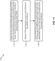
- Fig. 11 is a diagram illustrating an example process 1100 performed, for example, by a UE, in accordance with various aspects of the present disclosure.
- Example process 1100 is an example where a UE (e.g., UE 120 and/or the like) performs operations associated with PTRS port or configuration sharing across multiple physical downlink channels of TRPs.
- a UE e.g., UE 120 and/or the like
- process 1100 may include determining that a PTRS port is to be shared among a plurality of PDSCHs transmitted by a plurality of TRPs (block 1110).
- the UE e.g., using controller/processor 280 and/or the like
- process 1100 may include receiving PTRS pilot signals on one or more PDSCHs of the plurality of PDSCHs (block 1120).
- the UE e.g., using antenna 252, DEMOD 254, MIMO detector 256, receive processor 258, controller/processor 280, and/or the like
- process 1100 may include using the PTRS pilot signals for phase tracking estimation for the plurality of PDSCHs based at least in part on the determination that the PTRS port is to be shared among the plurality of PDSCHs (block 1130).
- the UE e.g., using controller/processor 280 and/or the like
- Process 1100 may include additional aspects, such as any single aspect or any combination of aspects described below and/or in connection with one or more other processes described elsewhere herein.
- using the PTRS pilot signals for phase tracking estimation for the plurality of PDSCHs comprises using different PTRS, of the PTRS pilot signals, to estimate a same set of phase tracking parameters for the plurality of PDSCHs.
- the determination that the PTRS port is to be shared among the plurality of PDSCHs is based at least in part on a determination that the plurality of PDSCHs are scheduled by the same downlink control information.
- the determination that the PTRS port is to be shared among the plurality of PDSCHs is based at least in part on a determination that the plurality of PDSCHs use the same set of demodulation reference signal (DMRS) ports.
- DMRS demodulation reference signal
- the determination that the PTRS port is to be shared among the plurality of PDSCHs is based at least in part on a determination that the plurality of PDSCHs carry the same transport block.
- the determination that the PTRS port is to be shared among the plurality of PDSCHs is based at least in part on an explicit indication from a base station.
- the explicit indication is indicated in a radio resource control (RRC) message.
- RRC radio resource control
- the determination that the PTRS port is to be shared among the plurality of PDSCHs is based at least in part on an indication that one or more ports associated with the plurality of PDSCHs are quasi co-located with respect to Doppler shift or belong to a group of ports having the same phase shift.
- the one or more ports include one or more PTRS ports or one or more DMRS ports.
- the determination that the PTRS port is to be shared among the plurality of PDSCHs is based at least in part on a determination that the plurality of PDSCHS are scheduled to completely overlap in a time domain.
- the determination that the PTRS port is to be shared among the plurality of PDSCHs is based at least in part on a determination that the plurality of PDSCHs belong to the same component carrier or bandwidth part.
- the determination that the PTRS port is to be shared among the plurality of PDSCHs is based at least in part on a determination that a condition is satisfied for the plurality of PDSCHs and an indication that the PTRS port is to be shared among the plurality of PDSCHs when the condition is satisfied.
- the indication includes an explicit indication in at least one of an RRC message or downlink control information (DCI).
- DCI downlink control information
- the indication includes an implicit indication in at least one of an RRC message or DCI.
- the condition includes at least one of: the plurality of PDSCHs being scheduled by the same downlink control information, the plurality of PDSCHs using the same set of DMRS ports, the plurality of PDSCHs carrying the same transport block, one or more ports, associated with the plurality of PDSCHs, being quasi co-located with respect to Doppler shift or belonging to a group of ports having the same phase shift, the plurality of PDSCHs being scheduled to completely overlap in a time domain, the plurality of PDSCHs belonging to the same component carrier or bandwidth part, or a combination thereof.
- the determination that the PTRS port is to be shared among the plurality of PDSCHs is based at least in part on a capability of the UE to support PTRS port sharing among the plurality of PDSCHs.
- the UE may be configured to identify the one or more PDSCHs that carry the PTRS pilot signals.
- the one or more PDSCHs that carry the PTRS pilot signals include all PDSCHs in the plurality of PDSCHs.
- the one or more PDSCHs that carry the PTRS pilot signals include multiple PDSCHs, and PTRS patterns for the PTRS pilot signals on different PDSCHs, of the multiple PDSCHs, are independent of one another.
- the one or more PDSCHs that carry the PTRS pilot signals include multiple PDSCHs, and a PTRS pattern for the PTRS pilot signals is the same across the multiple PDSCHs.
- the PTRS pattern is a densest pattern of multiple PTRS patterns determined for the multiple PDSCHs.
- the PTRS pattern is identified based at least in part on one or more of: an indication from a base station, respective identifiers corresponding to the plurality of PDSCHs, respective bandwidths corresponding to the plurality of PDSCHs, an ordering of the plurality of PDSCHs in DCI, feedback provided by the UE to a base station, or a combination thereof.
- the one or more PDSCHs that carry the PTRS pilot signals includes a single PDSCH included in the plurality of PDSCHs.
- the one or more PDSCHs that carry the PTRS pilot signals are identified based at least in part on an indication from a base station.
- the indication is included in an RRC message.
- the one or more PDSCHs that carry the PTRS pilot signals are identified based at least in part on a plurality of identifiers corresponding to the plurality of PDSCHs, wherein the plurality of identifiers includes at least one of: a plurality of control resource set (CORESET) identifiers corresponding to the plurality of PDSCHs, a plurality of physical cell identifiers corresponding to the plurality of PDSCHs, a plurality of virtual cell identifiers corresponding to the plurality of PDSCHs, a plurality of quasi co-location identifiers corresponding to the plurality of PDSCHs, a plurality of quasi co-location group identifiers corresponding to the plurality of PDSCHs, a plurality of bandwidth part identifiers corresponding to the plurality of PDSCHs, or a combination thereof.
- CORESET control resource set
- the one or more PDSCHs that carry the PTRS pilot signals are identified based at least in part on a determination that an identifier, of the plurality of identifiers, matches a preconfigured identifier or satisfies a condition with respect to all other identifiers of the plurality of identifiers.
- the one or more PDSCHs that carry the PTRS pilot signals are identified based at least in part on a plurality of bandwidths corresponding to the plurality of PDSCHs when the plurality of PDSCHs are scheduled by the same downlink control information.
- the one or more PDSCHs have the largest bandwidth as compared to other PDSCHs included in the plurality of PDSCHs.
- the one or more PDSCHs that carry the PTRS pilot signals are identified based at least in part on an ordering of the plurality of PDSCHs in DCI when the plurality of PDSCHs are scheduled by the same DCI.
- the one or more PDSCHs that carry the PTRS pilot signals are identified based at least in part on feedback provided by the UE to a base station.
- the one or more PDSCHs that carry the PTRS pilot signals include a first PDSCH, configured on the same symbols as a second PDSCH, and a third PDSCH configured on disjoint symbols from the first PDSCH and the second PDSCH.
- process 1100 may include additional blocks, fewer blocks, different blocks, or differently arranged blocks than those depicted in Fig. 11 . Additionally, or alternatively, two or more of the blocks of process 1100 may be performed in parallel.
- Fig. 12 is a diagram illustrating an example process 1200 performed, for example, by a UE, in accordance with various aspects of the present disclosure.
- Example process 1200 is an example where a UE (e.g., UE 120 and/or the like) performs operations associated with PTRS port or configuration sharing across multiple physical downlink channels of TRPs.
- a UE e.g., UE 120 and/or the like
- process 1200 may include determining that the UE is to communicate with multiple TRPs using a specific multi-TRP mode, wherein the specific multi-TRP mode indicates a number of DCI communications to be used for scheduling and a number of PDSCHs to be scheduled by the number of DCI communications, wherein the number of PDSCHs are transmitted by the multiple TRPs (block 1210).
- the UE may determine that the UE is to communicate with multiple TRPs using a specific multi-TRP mode, wherein the specific multi-TRP mode indicates a number of DCI communications to be used for scheduling and a number of PDSCHs to be scheduled by the number of DCI communications, as described above in connection with Fig. 10 .
- the number of PDSCHs are transmitted by the multiple TRPs.
- process 1200 may include determining whether to use a shared PTRS configuration across the number of PDSCHs or separate PTRS configurations for the number of PDSCHs based at least in part on the specific multi-TRP mode (block 1220).
- the UE e.g., using controller/processor 280 and/or the like
- process 1200 may include selectively using the shared PTRS configuration or the separate PTRS configurations for phase tracking estimation on the number of PDSCHs based at least in part on the determination of whether to use the shared PTRS configuration or the separate PTRS configurations (block 1230).
- the UE e.g., using controller/processor 280 and/or the like
- Process 1200 may include additional aspects, such as any single aspect or any combination of aspects described below and/or in connection with one or more other processes described elsewhere herein.
- the shared PTRS configuration or each PTRS configuration, of the separate PTRS configurations indicates a plurality of PTRS patterns and corresponding conditions in which each of the plurality of PTRS patterns are to be applied.
- the shared PTRS configuration is used when the specific multi-TRP mode is a first multi-TRP mode that indicates that a single DCI communication is to be used to schedule a single PDSCH transmitted by the multiple TRPs.
- the determination of whether to use the shared PTRS configuration or the separate PTRS configurations is based at least in part on an indication in an RRC message.
- the indication is included in the RRC message when the specific multi-TRP mode is a second multi-TRP mode, that indicates that a single DCI communication is to be used to schedule multiple PDSCHs transmitted by the multiple TRPs, or a third multi-TRP mode that indicates that multiple DCI communications are to be used to schedule multiple PDSCHs transmitted by the multiple TRPs.
- the determination of whether to use the shared PTRS configuration or the separate PTRS configurations is based at least in part on a capability of the UE to support the shared PTRS configuration or the separate PTRS configurations.
- the specific multi-TRP mode is a second multi-TRP mode that indicates that a single DCI communication is to be used to schedule multiple PDSCHs transmitted by the multiple TRPs, and a size of the single DCI communication depends on whether PTRS ports are shared across the multiple PDSCHs.
- the specific multi-TRP mode is a third multi-TRP mode that indicates that multiple DCI communications are to be used to schedule multiple PDSCHs transmitted by the multiple TRPs, and a size of one or more DCI communications, of the multiple DCI communications, depends on whether PTRS ports are shared across the multiple PDSCHs.
- the specific multi-TRP mode is a fourth multi-TRP mode that indicates that multiple DCI communications are to be used to schedule a single PDSCH transmitted by the multiple TRPs, and each DCI communication, of the multiple DCI communications, indicates a same PTRS configuration.
- process 1200 may include additional blocks, fewer blocks, different blocks, or differently arranged blocks than those depicted in Fig. 12 . Additionally, or alternatively, two or more of the blocks of process 1200 may be performed in parallel.
- the term component is intended to be broadly construed as hardware, firmware, or a combination of hardware and software.
- a processor is implemented in hardware, firmware, or a combination of hardware and software.
- satisfying a threshold may refer to a value being greater than the threshold, greater than or equal to the threshold, less than the threshold, less than or equal to the threshold, equal to the threshold, not equal to the threshold, and/or the like.
- "at least one of: a, b, or c” is intended to cover a, b, c, a-b, a-c, b-c, and a-b-c, as well as any combination with multiples of the same element (e.g., a-a, a-a-a, a-a-b, a-a-c, a-b-b, a-c-c, b-b, b-b-b, b-b-c, c-c, and c-c-c or any other ordering of a, b, and c).
- Using the PTRS pilot signals for phase tracking estimation for the plurality of PDSCHs may comprise using different PTRS, of the PTRS pilot signals, to estimate a same set of phase tracking parameters for the plurality of PDSCHs.
- the determination that the PTRS port is to be shared among the plurality of PDSCHs may be based at least in part on:
- the determination that the PTRS port is to be shared among the plurality of PDSCHs may be based at least in part on a determination that a condition is satisfied for the plurality of PDSCHs and an indication that the PTRS port is to be shared among the plurality of PDSCHs when the condition is satisfied.
- the indication may include an indication in at least one of a radio resource control (RRC) message or downlink control information (DCI).
- RRC radio resource control
- DCI downlink control information
- the condition may include at least one of:
- the method may further comprise identifying the one or more PDSCHs that carry the PTRS pilot signals.
- the one or more PDSCHs that carry the PTRS pilot signals may include all PDSCHs in the plurality of PDSCHs.
- the one or more PDSCHs that carry the PTRS pilot signals may include multiple PDSCHs, and wherein PTRS patterns for the PTRS pilot signals on different PDSCHs, of the multiple PDSCHs, are independent of one another.
- the one or more PDSCHs that carry the PTRS pilot signals may include multiple PDSCHs, and wherein a PTRS pattern for the PTRS pilot signals is the same across the multiple PDSCHs.
- the PTRS pattern may be a densest pattern of multiple PTRS patterns determined for the multiple PDSCHs.
- the PTRS pattern may be identified based at least in part on one or more of:
- the one or more PDSCHs that carry the PTRS pilot signals may include a single PDSCH included in the plurality of PDSCHs.
- the one or more PDSCHs that carry the PTRS pilot signals may be identified based at least in part on at least one of:
- the plurality of identifiers may include at least one of:
- the one or more PDSCHs that carry the PTRS pilot signals may be identified based at least in part on a determination that an identifier, of the plurality of identifiers, matches a preconfigured identifier or satisfies a condition with respect to all other identifiers of the plurality of identifiers.
- the one or more PDSCHs that carry the PTRS pilot signals may include a first PDSCH, configured on the same symbols as a second PDSCH, and a third PDSCH configured on disjoint symbols from the first PDSCH and the second PDSCH.
- a user equipment, UE for wireless communication, comprising:
- the determination that the PTRS port is to be shared among the plurality of PDSCHs may be based at least in part on:
Landscapes
- Engineering & Computer Science (AREA)
- Signal Processing (AREA)
- Computer Networks & Wireless Communication (AREA)
- Mobile Radio Communication Systems (AREA)
Applications Claiming Priority (4)
| Application Number | Priority Date | Filing Date | Title |
|---|---|---|---|
| GR20180100375 | 2018-08-08 | ||
| US16/526,804 US11108613B2 (en) | 2018-08-08 | 2019-07-30 | Phase tracking reference signal port or configuration sharing across multiple physical downlink channels of multiple transmit receive points |
| EP19752612.2A EP3834334B1 (fr) | 2018-08-08 | 2019-07-31 | Port de signal de référence de suivi de phase ou partage de configuration sur de multiples canaux de liaison descendante physiques de multiples points de réception de transmission |
| PCT/US2019/044341 WO2020033198A1 (fr) | 2018-08-08 | 2019-07-31 | Port de signal de référence de suivi de phase ou partage de configuration sur de multiples canaux de liaison descendante physiques de multiples points de réception de transmission |
Related Parent Applications (2)
| Application Number | Title | Priority Date | Filing Date |
|---|---|---|---|
| EP19752612.2A Division EP3834334B1 (fr) | 2018-08-08 | 2019-07-31 | Port de signal de référence de suivi de phase ou partage de configuration sur de multiples canaux de liaison descendante physiques de multiples points de réception de transmission |
| EP19752612.2A Division-Into EP3834334B1 (fr) | 2018-08-08 | 2019-07-31 | Port de signal de référence de suivi de phase ou partage de configuration sur de multiples canaux de liaison descendante physiques de multiples points de réception de transmission |
Publications (3)
| Publication Number | Publication Date |
|---|---|
| EP4277191A2 true EP4277191A2 (fr) | 2023-11-15 |
| EP4277191A3 EP4277191A3 (fr) | 2023-12-27 |
| EP4277191B1 EP4277191B1 (fr) | 2026-04-01 |
Family
ID=69406929
Family Applications (2)
| Application Number | Title | Priority Date | Filing Date |
|---|---|---|---|
| EP19752612.2A Active EP3834334B1 (fr) | 2018-08-08 | 2019-07-31 | Port de signal de référence de suivi de phase ou partage de configuration sur de multiples canaux de liaison descendante physiques de multiples points de réception de transmission |
| EP23195697.0A Active EP4277191B1 (fr) | 2018-08-08 | 2019-07-31 | Port de signal de référence de suivi de phase ou partage de configuration sur de multiples canaux de liaison descendante physiques de multiples points de réception de transmission |
Family Applications Before (1)
| Application Number | Title | Priority Date | Filing Date |
|---|---|---|---|
| EP19752612.2A Active EP3834334B1 (fr) | 2018-08-08 | 2019-07-31 | Port de signal de référence de suivi de phase ou partage de configuration sur de multiples canaux de liaison descendante physiques de multiples points de réception de transmission |
Country Status (4)
| Country | Link |
|---|---|
| US (1) | US11108613B2 (fr) |
| EP (2) | EP3834334B1 (fr) |
| CN (2) | CN112514311B (fr) |
| WO (1) | WO2020033198A1 (fr) |
Cited By (2)
| Publication number | Priority date | Publication date | Assignee | Title |
|---|---|---|---|---|
| US20230179260A1 (en) * | 2020-06-30 | 2023-06-08 | Qualcomm Incorporated | Indication of doppler pre-compensation in multi-transmission reception point communications |
| US20240396682A1 (en) * | 2023-05-26 | 2024-11-28 | Qualcomm Incorporated | Cross-phase tracking reference signal rate matching for multiple coordinated transmit receive points with multiple downlink control information |
Families Citing this family (30)
| Publication number | Priority date | Publication date | Assignee | Title |
|---|---|---|---|---|
| WO2020130746A1 (fr) * | 2018-12-21 | 2020-06-25 | 엘지전자 주식회사 | Procédé d'exploitation d'un terminal et d'une station de base dans un système de communication sans fil et appareil permettant de prendre en charge ledit procédé |
| EP4037223B1 (fr) * | 2019-09-29 | 2025-08-06 | Fujitsu Limited | Procédé et appareil destinés à émettre un signal de référence de suivi de phase |
| CN111082911B (zh) * | 2019-09-30 | 2024-10-08 | 中兴通讯股份有限公司 | 一种参考信号的接收、发送方法及装置 |
| ES3004959T3 (en) | 2019-11-08 | 2025-03-13 | Ericsson Telefon Ab L M | Determining phase tracking reference signals in multiple transmission points |
| US11476894B2 (en) | 2019-12-10 | 2022-10-18 | AR & NS Investment, LLC | Edge communication system with cascaded repeater devices over wired medium |
| CN113271190B (zh) | 2020-02-14 | 2023-03-28 | 华为技术有限公司 | 信号解调方法、信号传输方法及相关装置 |
| US20230223999A1 (en) * | 2020-04-06 | 2023-07-13 | Telefonaktiebolaget Lm Ericsson (Publ) | Nb-iot realization in active antenna system |
| US11671929B2 (en) * | 2020-04-10 | 2023-06-06 | Qualcomm Incorporated | Techniques for communication link synchronization using reference signals |
| US11723023B2 (en) * | 2020-05-07 | 2023-08-08 | Samsung Electronics Co., Ltd. | System and method for managing collisions in multiple-transmission-and-reception-points communications |
| US12244528B2 (en) * | 2020-05-19 | 2025-03-04 | Qualcomm Incorporated | Amplitude modulated phase tracking reference signals |
| US11283510B2 (en) * | 2020-06-24 | 2022-03-22 | AR & NS Investment, LLC | Phase noise removal in a network of radio frequency (RF) repeaters |
| US11989965B2 (en) | 2020-06-24 | 2024-05-21 | AR & NS Investment, LLC | Cross-correlation system and method for spatial detection using a network of RF repeaters |
| US11711126B2 (en) | 2020-06-24 | 2023-07-25 | AR & NS Investment, LLC | Wireless communication system based on mmWave RF repeaters |
| US11177872B1 (en) | 2020-06-24 | 2021-11-16 | AR & NS Investment, LLC | Managing a network of radio frequency (RF) repeater devices |
| WO2022016503A1 (fr) * | 2020-07-24 | 2022-01-27 | Qualcomm Incorporated | Configurations de signal de référence de suivi de phase multiple pour un équipement utilisateur |
| WO2022027361A1 (fr) * | 2020-08-05 | 2022-02-10 | Apple Inc. | Système et procédé de compensation doppler à grande vitesse dans un environnement cellulaire |
| CN114070677A (zh) * | 2020-08-06 | 2022-02-18 | 北京三星通信技术研究有限公司 | 通信方法及执行该通信方法的终端 |
| US11115086B1 (en) * | 2020-09-01 | 2021-09-07 | Qualcomm Incorporated | Reference signal port allocation |
| US12009962B2 (en) * | 2020-10-06 | 2024-06-11 | Qualcomm Incorporated | Changing the phase tracking reference signal (PTRS) pattern over different symbols |
| US12477562B2 (en) * | 2020-10-13 | 2025-11-18 | Beijing Xiaomi Mobile Software Co., Ltd. | Downlink control information scheduling method and apparatus, and storage medium |
| CN114826839B (zh) * | 2021-01-27 | 2024-11-05 | 大唐移动通信设备有限公司 | 相位噪声补偿方法、终端设备及网络设备 |
| WO2022207960A1 (fr) * | 2021-04-01 | 2022-10-06 | Nokia Technologies Oy | Motif de signal de référence de suivi de phase agrégé |
| US11632750B2 (en) * | 2021-04-02 | 2023-04-18 | Nokia Technologies Oy | Inter-cell multi-TRP operation for wireless networks |
| US12232189B2 (en) * | 2021-04-16 | 2025-02-18 | Qualcomm Incorporated | Phase tracking reference signal transmission in a radio resource control connection request message |
| KR20220166656A (ko) * | 2021-06-10 | 2022-12-19 | 삼성전자주식회사 | 네트워크 협력 통신에서 하향링크 데이터 송수신 방법 및 장치 |
| US11895049B2 (en) * | 2021-08-18 | 2024-02-06 | Qualcomm Incorporated | Phase noise (PN) mitigation pilot allocation on a single component carrier (CC) for PN mitigation on multiple CCs |
| US12224815B2 (en) * | 2021-09-21 | 2025-02-11 | Qualcomm Incorporated | Autonomous switching between single frequency network (SFN) and non-SFN scheme |
| CN116582160A (zh) * | 2022-01-29 | 2023-08-11 | 维沃移动通信有限公司 | 能力信息上报方法、装置及终端 |
| US20230370212A1 (en) * | 2022-05-16 | 2023-11-16 | Qualcomm Incorporated | Bit loading with dft-s-ofdm |
| KR20260012027A (ko) * | 2024-07-17 | 2026-01-26 | 삼성전자주식회사 | 무선 통신 시스템에서 복수 pdsch 동시 수신을 위한 harq-ack 코드북 설계 방법 및 장치 |
Family Cites Families (8)
| Publication number | Priority date | Publication date | Assignee | Title |
|---|---|---|---|---|
| US10979191B2 (en) * | 2016-08-05 | 2021-04-13 | Samsung Electronics Co., Ltd. | Method and apparatus for reference signal signaling for advanced wireless communications |
| CN107888266B (zh) | 2016-09-30 | 2023-09-12 | 华为技术有限公司 | 一种准共址指示信息指示方法及设备 |
| US10998994B2 (en) * | 2016-10-11 | 2021-05-04 | Lg Electronics Inc. | Signal transmission method for removing phase noise in wireless communication system and device therefor |
| US10560243B2 (en) * | 2017-01-13 | 2020-02-11 | Qualcomm Incorporated | Systems and methods to select or transmitting frequency domain patterns for phase tracking reference signals |
| CN108632005B (zh) * | 2017-03-24 | 2023-12-15 | 华为技术有限公司 | 一种参考信号传输方法、装置及系统 |
| GB2562117B (en) * | 2017-05-05 | 2021-07-28 | Samsung Electronics Co Ltd | Phase tracking reference signal |
| US10972238B2 (en) * | 2017-06-09 | 2021-04-06 | Apple Inc. | System and method for phase tracking reference signal (PT-RS) multiplexing |
| KR102394214B1 (ko) * | 2017-08-10 | 2022-05-04 | 삼성전자 주식회사 | PTRS(Phase Tracking Reference Signal)를 할당하는 방법 및 장치 |
-
2019
- 2019-07-30 US US16/526,804 patent/US11108613B2/en active Active
- 2019-07-31 EP EP19752612.2A patent/EP3834334B1/fr active Active
- 2019-07-31 CN CN201980050596.7A patent/CN112514311B/zh active Active
- 2019-07-31 WO PCT/US2019/044341 patent/WO2020033198A1/fr not_active Ceased
- 2019-07-31 EP EP23195697.0A patent/EP4277191B1/fr active Active
- 2019-07-31 CN CN202410383592.3A patent/CN118054893A/zh active Pending
Cited By (3)
| Publication number | Priority date | Publication date | Assignee | Title |
|---|---|---|---|---|
| US20230179260A1 (en) * | 2020-06-30 | 2023-06-08 | Qualcomm Incorporated | Indication of doppler pre-compensation in multi-transmission reception point communications |
| US12381599B2 (en) * | 2020-06-30 | 2025-08-05 | Qualcomm Incorporated | Indication of doppler pre-compensation in multi-transmission reception point communications |
| US20240396682A1 (en) * | 2023-05-26 | 2024-11-28 | Qualcomm Incorporated | Cross-phase tracking reference signal rate matching for multiple coordinated transmit receive points with multiple downlink control information |
Also Published As
| Publication number | Publication date |
|---|---|
| CN112514311B (zh) | 2024-04-12 |
| CN112514311A (zh) | 2021-03-16 |
| US11108613B2 (en) | 2021-08-31 |
| EP4277191B1 (fr) | 2026-04-01 |
| EP3834334B1 (fr) | 2023-11-01 |
| EP3834334A1 (fr) | 2021-06-16 |
| US20200052950A1 (en) | 2020-02-13 |
| WO2020033198A1 (fr) | 2020-02-13 |
| EP4277191A3 (fr) | 2023-12-27 |
| CN118054893A (zh) | 2024-05-17 |
Similar Documents
| Publication | Publication Date | Title |
|---|---|---|
| EP3834334B1 (fr) | Port de signal de référence de suivi de phase ou partage de configuration sur de multiples canaux de liaison descendante physiques de multiples points de réception de transmission | |
| US11159270B2 (en) | Separately communicating demodulation reference signal-based channel information for multiple transmit receive points | |
| US11683709B2 (en) | Indicating a user equipment capability for crosslink interference measurement | |
| US10720981B2 (en) | Spatial multiplexing of a sounding reference signal (SRS) and a physical uplink shared channel (PUSCH) communication | |
| US10979927B2 (en) | Cross link interference measurement and reporting | |
| US11265122B2 (en) | Multi-transmit receive point demodulation reference signal port identification | |
| US12323355B2 (en) | Demodulation reference signal design for large sub-carrier spacing | |
| CN112470512A (zh) | 用于不同发送接收点的单独测量和报告 | |
| US11057917B2 (en) | Quasi co-location relation configuration for periodic channel state information reference signals | |
| US20210076243A1 (en) | Deriving csi using a subset of configured csi-rs resources | |
| AU2019249173B2 (en) | Group CSI feedback for multicast/broadcast transmission | |
| US11564244B2 (en) | Multiple link communication constraint | |
| US12471098B2 (en) | Physical uplink control channel (PUCCH) repetition across multiple component carriers | |
| EP4032218B1 (fr) | Techniques de planification d'un signal de référence d'informations d'état de canal de liaison latérale à chargement frontal | |
| US12040867B2 (en) | Differential reporting mode for amplitude and/or co-phase | |
| US11265890B2 (en) | Resource rate matching for remote interference management | |
| WO2021146992A1 (fr) | Rapport d'informations d'état de canal commun (csi) à l'aide de sous-rapports pour de multiples points de réception d'émission | |
| US10886995B2 (en) | Beam management signaling | |
| US12500641B2 (en) | Subband reporting for channel state information of multiple transmission reception points |
Legal Events
| Date | Code | Title | Description |
|---|---|---|---|
| PUAI | Public reference made under article 153(3) epc to a published international application that has entered the european phase |
Free format text: ORIGINAL CODE: 0009012 |
|
| STAA | Information on the status of an ep patent application or granted ep patent |
Free format text: STATUS: REQUEST FOR EXAMINATION WAS MADE |
|
| 17P | Request for examination filed |
Effective date: 20230906 |
|
| AC | Divisional application: reference to earlier application |
Ref document number: 3834334 Country of ref document: EP Kind code of ref document: P |
|
| AK | Designated contracting states |
Kind code of ref document: A2 Designated state(s): AL AT BE BG CH CY CZ DE DK EE ES FI FR GB GR HR HU IE IS IT LI LT LU LV MC MK MT NL NO PL PT RO RS SE SI SK SM TR |
|
| PUAL | Search report despatched |
Free format text: ORIGINAL CODE: 0009013 |
|
| AK | Designated contracting states |
Kind code of ref document: A3 Designated state(s): AL AT BE BG CH CY CZ DE DK EE ES FI FR GB GR HR HU IE IS IT LI LT LU LV MC MK MT NL NO PL PT RO RS SE SI SK SM TR |
|
| RIC1 | Information provided on ipc code assigned before grant |
Ipc: H04L 5/00 20060101AFI20231121BHEP |
|
| STAA | Information on the status of an ep patent application or granted ep patent |
Free format text: STATUS: EXAMINATION IS IN PROGRESS |
|
| 17Q | First examination report despatched |
Effective date: 20250221 |
|
| GRAP | Despatch of communication of intention to grant a patent |
Free format text: ORIGINAL CODE: EPIDOSNIGR1 |
|
| STAA | Information on the status of an ep patent application or granted ep patent |
Free format text: STATUS: GRANT OF PATENT IS INTENDED |
|
| INTG | Intention to grant announced |
Effective date: 20251114 |
|
| GRAS | Grant fee paid |
Free format text: ORIGINAL CODE: EPIDOSNIGR3 |
|
| GRAA | (expected) grant |
Free format text: ORIGINAL CODE: 0009210 |
|
| STAA | Information on the status of an ep patent application or granted ep patent |
Free format text: STATUS: THE PATENT HAS BEEN GRANTED |
|
| AC | Divisional application: reference to earlier application |
Ref document number: 3834334 Country of ref document: EP Kind code of ref document: P |
|
| AK | Designated contracting states |
Kind code of ref document: B1 Designated state(s): AL AT BE BG CH CY CZ DE DK EE ES FI FR GB GR HR HU IE IS IT LI LT LU LV MC MK MT NL NO PL PT RO RS SE SI SK SM TR |
|
| REG | Reference to a national code |
Ref country code: CH Ref legal event code: F10 Free format text: ST27 STATUS EVENT CODE: U-0-0-F10-F00 (AS PROVIDED BY THE NATIONAL OFFICE) Effective date: 20260401 Ref country code: GB Ref legal event code: FG4D |
|
| REG | Reference to a national code |
Ref country code: IE Ref legal event code: FG4D |
|
| REG | Reference to a national code |
Ref country code: DE Ref legal event code: R096 Ref document number: 602019083282 Country of ref document: DE |