EP4277214A2 - Berichterstattung von kanalstatusinformationen - Google Patents
Berichterstattung von kanalstatusinformationen Download PDFInfo
- Publication number
- EP4277214A2 EP4277214A2 EP23200488.7A EP23200488A EP4277214A2 EP 4277214 A2 EP4277214 A2 EP 4277214A2 EP 23200488 A EP23200488 A EP 23200488A EP 4277214 A2 EP4277214 A2 EP 4277214A2
- Authority
- EP
- European Patent Office
- Prior art keywords
- csi
- ports
- channel
- configuration
- resources
- Prior art date
- Legal status (The legal status is an assumption and is not a legal conclusion. Google has not performed a legal analysis and makes no representation as to the accuracy of the status listed.)
- Pending
Links
Images


Classifications
-
- H—ELECTRICITY
- H04—ELECTRIC COMMUNICATION TECHNIQUE
- H04B—TRANSMISSION
- H04B7/00—Radio transmission systems, i.e. using radiation field
- H04B7/02—Diversity systems; Multi-antenna system, i.e. transmission or reception using multiple antennas
- H04B7/04—Diversity systems; Multi-antenna system, i.e. transmission or reception using multiple antennas using two or more spaced independent antennas
- H04B7/06—Diversity systems; Multi-antenna system, i.e. transmission or reception using multiple antennas using two or more spaced independent antennas at the transmitting station
- H04B7/0613—Diversity systems; Multi-antenna system, i.e. transmission or reception using multiple antennas using two or more spaced independent antennas at the transmitting station using simultaneous transmission
- H04B7/0615—Diversity systems; Multi-antenna system, i.e. transmission or reception using multiple antennas using two or more spaced independent antennas at the transmitting station using simultaneous transmission of weighted versions of same signal
- H04B7/0619—Diversity systems; Multi-antenna system, i.e. transmission or reception using multiple antennas using two or more spaced independent antennas at the transmitting station using simultaneous transmission of weighted versions of same signal using feedback from receiving side
- H04B7/0621—Feedback content
- H04B7/0632—Channel quality parameters, e.g. channel quality indicator [CQI]
-
- H—ELECTRICITY
- H04—ELECTRIC COMMUNICATION TECHNIQUE
- H04B—TRANSMISSION
- H04B7/00—Radio transmission systems, i.e. using radiation field
- H04B7/02—Diversity systems; Multi-antenna system, i.e. transmission or reception using multiple antennas
- H04B7/04—Diversity systems; Multi-antenna system, i.e. transmission or reception using multiple antennas using two or more spaced independent antennas
- H04B7/0413—MIMO systems
- H04B7/0417—Feedback systems
-
- H—ELECTRICITY
- H04—ELECTRIC COMMUNICATION TECHNIQUE
- H04B—TRANSMISSION
- H04B7/00—Radio transmission systems, i.e. using radiation field
- H04B7/02—Diversity systems; Multi-antenna system, i.e. transmission or reception using multiple antennas
- H04B7/04—Diversity systems; Multi-antenna system, i.e. transmission or reception using multiple antennas using two or more spaced independent antennas
- H04B7/06—Diversity systems; Multi-antenna system, i.e. transmission or reception using multiple antennas using two or more spaced independent antennas at the transmitting station
- H04B7/0613—Diversity systems; Multi-antenna system, i.e. transmission or reception using multiple antennas using two or more spaced independent antennas at the transmitting station using simultaneous transmission
- H04B7/0615—Diversity systems; Multi-antenna system, i.e. transmission or reception using multiple antennas using two or more spaced independent antennas at the transmitting station using simultaneous transmission of weighted versions of same signal
- H04B7/0619—Diversity systems; Multi-antenna system, i.e. transmission or reception using multiple antennas using two or more spaced independent antennas at the transmitting station using simultaneous transmission of weighted versions of same signal using feedback from receiving side
- H04B7/0621—Feedback content
- H04B7/0626—Channel coefficients, e.g. channel state information [CSI]
-
- H—ELECTRICITY
- H04—ELECTRIC COMMUNICATION TECHNIQUE
- H04B—TRANSMISSION
- H04B7/00—Radio transmission systems, i.e. using radiation field
- H04B7/02—Diversity systems; Multi-antenna system, i.e. transmission or reception using multiple antennas
- H04B7/04—Diversity systems; Multi-antenna system, i.e. transmission or reception using multiple antennas using two or more spaced independent antennas
- H04B7/06—Diversity systems; Multi-antenna system, i.e. transmission or reception using multiple antennas using two or more spaced independent antennas at the transmitting station
- H04B7/0613—Diversity systems; Multi-antenna system, i.e. transmission or reception using multiple antennas using two or more spaced independent antennas at the transmitting station using simultaneous transmission
- H04B7/0615—Diversity systems; Multi-antenna system, i.e. transmission or reception using multiple antennas using two or more spaced independent antennas at the transmitting station using simultaneous transmission of weighted versions of same signal
- H04B7/0619—Diversity systems; Multi-antenna system, i.e. transmission or reception using multiple antennas using two or more spaced independent antennas at the transmitting station using simultaneous transmission of weighted versions of same signal using feedback from receiving side
- H04B7/0636—Feedback format
- H04B7/0639—Using selective indices, e.g. of a codebook, e.g. pre-distortion matrix index [PMI] or for beam selection
-
- H—ELECTRICITY
- H04—ELECTRIC COMMUNICATION TECHNIQUE
- H04L—TRANSMISSION OF DIGITAL INFORMATION, e.g. TELEGRAPHIC COMMUNICATION
- H04L25/00—Baseband systems
- H04L25/02—Details ; arrangements for supplying electrical power along data transmission lines
- H04L25/0202—Channel estimation
- H04L25/0204—Channel estimation of multiple channels
-
- H—ELECTRICITY
- H04—ELECTRIC COMMUNICATION TECHNIQUE
- H04L—TRANSMISSION OF DIGITAL INFORMATION, e.g. TELEGRAPHIC COMMUNICATION
- H04L5/00—Arrangements affording multiple use of the transmission path
- H04L5/003—Arrangements for allocating sub-channels of the transmission path
- H04L5/0048—Allocation of pilot signals, i.e. of signals known to the receiver
- H04L5/0051—Allocation of pilot signals, i.e. of signals known to the receiver of dedicated pilots, i.e. pilots destined for a single user or terminal
-
- H—ELECTRICITY
- H04—ELECTRIC COMMUNICATION TECHNIQUE
- H04W—WIRELESS COMMUNICATION NETWORKS
- H04W24/00—Supervisory, monitoring or testing arrangements
- H04W24/10—Scheduling measurement reports ; Arrangements for measurement reports
-
- H—ELECTRICITY
- H04—ELECTRIC COMMUNICATION TECHNIQUE
- H04L—TRANSMISSION OF DIGITAL INFORMATION, e.g. TELEGRAPHIC COMMUNICATION
- H04L25/00—Baseband systems
- H04L25/02—Details ; arrangements for supplying electrical power along data transmission lines
- H04L25/0202—Channel estimation
- H04L25/0224—Channel estimation using sounding signals
Definitions
- This application relates generally to wireless communication systems, and in particular relates to channel state information reporting.
- the 5G NR network may assign one or more frequency sub-bands to a user equipment (UE) to exchange information with the network. These sub-bands are allocated to the UE based on measured channel conditions that the UE reports to a next generation NodeB (gNB) of the network based on channel state information (CSI) measurements conducted by the UE on a CSI reference signal (CSI-RS).
- gNB next generation NodeB
- CSI-RS channel state information
- channel reciprocity may be used by the gNB to determine downlink (DL) channel conditions based on the CSI measurements provided by the UE for the uplink (UL) channel.
- 3GPP Release 15 and Release 16 provide a type II port selection codebook that exploits this channel reciprocity.
- Some exemplary embodiments are related to a user equipment (UE) having a transceiver configured to connect to a base station and a processor communicatively coupled to the transceiver and configured to perform operations.
- the operations include transmitting, to the base station, a first sounding reference signal (SRS) on an uplink (UL) channel, receiving, from the base station, a first channel state information reference signal (CSI-RS) on a downlink (DL) channel, wherein the first CSI-RS includes a first configuration of CSI-RS parameters based on the first SRS, performing first CSI-RS measurements based on the first configuration of CSI-RS parameters, transmitting, to the base station, a first CSI report including the first CSI-RS measurements, transmitting, to the base station, a second SRS on the UL channel, receiving, from the base station, a second CSI-RS on the DL channel, wherein the second CSI-RS includes a second configuration of CSI-RS parameters based on the second SRS, performing second CSI
- the operations include transmitting, to a base station of a wireless network, a first sounding reference signal (SRS) on an uplink (UL) channel, receiving, from the base station, a first channel state information reference signal (CSI-RS) on a downlink (DL) channel, wherein the first CSI-RS includes a first configuration of CSI-RS parameters based on the first SRS, performing first CSI-RS measurements based on the first configuration of CSI-RS parameters, transmitting, to the base station, a first CSI report including the first CSI-RS measurements, transmitting, to the base station, a second SRS on the UL channel, receiving, from the base station, a second CSI-RS on the DL channel, wherein the second CSI-RS includes a second configuration of CSI-RS parameters based on the second SRS, performing second CSI-RS measurements based on the second configuration of CSI-RS parameters and transmitting, to the base station, a second CSI report
- SRS sounding reference signal
- CSI-RS channel state information
- Still further exemplary embodiments are related to a method that includes transmitting, to a base station, a first sounding reference signal (SRS) on an uplink (UL) channel of a wireless network, receiving, from the base station, a first channel state information reference signal (CSI-RS) on a downlink (DL) channel, wherein the first CSI-RS includes a first configuration of CSI-RS parameters based on the first SRS, performing first CSI-RS measurements based on the first configuration of CSI-RS parameters, transmitting, to the base station, a first CSI report including the first CSI-RS measurements, transmitting, to the base station, a second SRS on the UL channel, receiving, from the base station, a second CSI-RS on the DL channel, wherein the second CSI-RS includes a second configuration of CSI-RS parameters based on the second SRS, performing second CSI-RS measurements based on the second configuration of CSI-RS parameters and transmitting, to the base station, a second CSI report including the second CSI-
- the exemplary embodiments may be further understood with reference to the following description and the related appended drawings, wherein like elements are provided with the same reference numerals.
- the exemplary embodiments describe a device, system and method for a 5G new radio (NR) network to improve channel state information (CSI) configuration of a user equipment (UE).
- NR new radio
- CSI channel state information
- the exemplary embodiments are described with regard to a network that includes 5G new radio NR radio access technology (RAT). However, the exemplary embodiments may be implemented in other types of networks using the principles described herein.
- RAT new radio NR radio access technology
- the exemplary embodiments are also described with regard to a UE.
- the use of a UE is merely for illustrative purposes.
- the exemplary embodiments may be utilized with any electronic component that may establish a connection with a network and is configured with the hardware, software, and/or firmware to exchange information and data with the network. Therefore, the UE as described herein is used to represent any electronic component.
- TDD communications channel reciprocity may be used by the gNB to determine downlink (DL) channel conditions based on the CSI measurements provided by the UE for the uplink (UL) channel.
- exact reciprocity does not exist in frequency division duplexing (FDD) communications as it does in TDD
- partial reciprocity may exist.
- FDD communications the angle of arrival/departure and the channel delay profile are similar between the UL and DL carriers.
- 5G NR communications do not exploit the partial reciprocity exhibited by FDD communications.
- partial channel reciprocity in FDD is exploited to allow for CSI report reconfigurations to address a change in channel conditions and to reduce the overhead at the UE associated with performing CSI measurements.
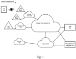
- Fig. 1 shows an exemplary network arrangement 100 according to various exemplary embodiments.
- the exemplary network arrangement 100 includes a UE 110.
- UE 110 may alternatively be any type of electronic component that is configured to communicate via a network, e.g., mobile phones, tablet computers, desktop computers, smartphones, phablets, embedded devices, wearables, Internet of Things (IoT) devices, etc.
- IoT Internet of Things
- an actual network arrangement may include any number of UEs being used by any number of users.
- the example of a single UE 110 is merely provided for illustrative purposes.
- the UE 110 may be configured to communicate with one or more networks.
- the networks with which the UE 110 may wirelessly communicate are a 5G New Radio (NR) radio access network (5G NR-RAN) 120, an LTE radio access network (LTE-RAN) 122 and a wireless local access network (WLAN) 124.
- NR 5G New Radio
- LTE-RAN LTE radio access network
- WLAN wireless local access network
- the UE 110 may also communicate with other types of networks and the UE 110 may also communicate with networks over a wired connection. Therefore, the UE 110 may include a 5G NR chipset to communicate with the 5G NR-RAN 120, an LTE chipset to communicate with the LTE-RAN 122 and an ISM chipset to communicate with the WLAN 124.
- the 5G NR-RAN 120 and the LTE-RAN 122 may be portions of cellular networks that may be deployed by cellular providers (e.g., Verizon, AT&T, Sprint, T-Mobile, etc.). These networks 120, 122 may include, for example, cells or base stations (Node Bs, eNodeBs, HeNBs, eNBS, gNBs, gNodeBs, macrocells, microcells, small cells, femtocells, etc.) that are configured to send and receive traffic from UE that are equipped with the appropriate cellular chip set.
- the WLAN 124 may include any type of wireless local area network (WiFi, Hot Spot, IEEE 802.11x networks, etc.).
- the UE 110 may connect to the 5G NR-RAN 120 via the gNB 120A and/or the gNB 120B. During operation, the UE 110 may be within range of a plurality of gNBs. Thus, either simultaneously or alternatively, the UE 110 may connect to the 5G NR-RAN 120 via the gNBs 120A and 120B. Further, the UE 110 may communicate with the eNB 122A of the LTE-RAN 122 to transmit and receive control information used for downlink and/or uplink synchronization with respect to the 5G NR-RAN 120 connection.
- any association procedure may be performed for the UE 110 to connect to the 5G NR-RAN 120.
- the 5G NR-RAN 120 may be associated with a particular cellular provider where the UE 110 and/or the user thereof has a contract and credential information (e.g., stored on a SIM card).
- the UE 110 may transmit the corresponding credential information to associate with the 5G NR-RAN 120.
- the UE 110 may associate with a specific base station (e.g., the gNB 120A of the 5G NR-RAN 120).
- the network arrangement 100 also includes a cellular core network 130, the Internet 140, an IP Multimedia Subsystem (IMS) 150, and a network services backbone 160.
- the cellular core network 130 may be considered to be the interconnected set of components that manages the operation and traffic of the cellular network, e.g. the 5GC for NR.
- the cellular core network 130 also manages the traffic that flows between the cellular network and the Internet 140.
- the IMS 150 may be generally described as an architecture for delivering multimedia services to the UE 110 using the IP protocol.
- the IMS 150 may communicate with the cellular core network 130 and the Internet 140 to provide the multimedia services to the UE 110.
- the network services backbone 160 is in communication either directly or indirectly with the Internet 140 and the cellular core network 130.
- the network services backbone 160 may be generally described as a set of components (e.g., servers, network storage arrangements, etc.) that implement a suite of services that may be used to extend the functionalities of the UE 110 in communication with the various networks.
- Fig. 2 shows an exemplary UE 110 according to various exemplary embodiments.
- the UE 110 will be described with regard to the network arrangement 100 of Fig. 1 .
- the UE 110 may represent any electronic device and may include a processor 205, a memory arrangement 210, a display device 215, an input/output (I/O) device 220, a transceiver 225 and other components 230.
- the other components 230 may include, for example, an audio input device, an audio output device, a battery that provides a limited power supply, a data acquisition device, ports to electrically connect the UE 110 to other electronic devices, one or more antenna panels, etc.
- the UE 110 may be coupled to an industrial device via one or more ports.
- the processor 205 may be configured to execute a plurality of engines of the UE 110.
- the engines may include a CSI management engine 235.
- the CSI management engine 235 may perform various operations related to performing CSI measurements on a channel and providing a CSI report back to the network (e.g., via the gNB).
- the above referenced engine being an application (e.g., a program) executed by the processor 205 is only exemplary.
- the functionality associated with the engine may also be represented as a separate incorporated component of the UE 110 or may be a modular component coupled to the UE 110, e.g., an integrated circuit with or without firmware.
- the integrated circuit may include input circuitry to receive signals and processing circuitry to process the signals and other information.
- the engines may also be embodied as one application or separate applications.
- the functionality described for the processor 205 is split among two or more processors such as a baseband processor and an applications processor.
- the exemplary embodiments may be implemented in any of these or other configurations of a UE.
- the memory arrangement 210 may be a hardware component configured to store data related to operations performed by the UE 110.
- the display device 215 may be a hardware component configured to show data to a user while the I/O device 220 may be a hardware component that enables the user to enter inputs.
- the display device 215 and the I/O device 220 may be separate components or integrated together such as a touchscreen.
- the transceiver 225 may be a hardware component configured to establish a connection with the 5G NR-RAN 120, the LTE-RAN 122, the WLAN 124, etc. Accordingly, the transceiver 225 may operate on a variety of different frequencies or channels (e.g., set of consecutive frequencies).
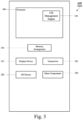
- Fig. 3 shows an exemplary network cell, in this case gNB 120A, according to various exemplary embodiments.
- the gNB 120A may represent any access node of the 5G NR network through which the UEs 110 may establish a connection.
- the gNB 120A illustrated in Fig. 3 may also represent the gNB 120B.
- the gNB 120A may include a processor 305, a memory arrangement 310, an input/output (I/O) device 320, a transceiver 325, and other components 330.
- the other components 330 may include, for example, a power supply, a data acquisition device, ports to electrically connect the gNB 120A to other electronic devices, etc.
- the processor 305 may be configured to execute a plurality of engines of the gNB 120A.
- the engines may include a CSI management engine 335 for performing operations including reconfiguration of CSI resources for the UE 110 to use in conducting CSI measurements. Examples of this process will be described in greater detail below.
- the above noted engine being an application (e.g., a program) executed by the processor 305 is only exemplary.
- the functionality associated with the engines may also be represented as a separate incorporated component of the gNB 120A or may be a modular component coupled to the gNB 120A, e.g., an integrated circuit with or without firmware.
- the integrated circuit may include input circuitry to receive signals and processing circuitry to process the signals and other information.
- the functionality described for the processor 305 is split among a plurality of processors (e.g., a baseband processor, an applications processor, etc.).
- the exemplary aspects may be implemented in any of these or other configurations of a gNB.
- the memory 310 may be a hardware component configured to store data related to operations performed by the UEs 110, 112.
- the I/O device 320 may be a hardware component or ports that enable a user to interact with the gNB 120A.
- the transceiver 325 may be a hardware component configured to exchange data with the UE 110 and any other UE in the system 100.
- the transceiver 325 may operate on a variety of different frequencies or channels (e.g., set of consecutive frequencies). Therefore, the transceiver 325 may include one or more components (e.g., radios) to enable the data exchange with the various networks and UEs.
- Fig. 4 shows a method 400 of reporting interference fluctuation according to various exemplary embodiments.
- the UE 110 sends a sounding reference signal (SRS) on the uplink (UL) channel to the gNB 120a (or 120b). Based on the SRS, the gNB 120a is apprised of the downlink (DL) channel due to partial reciprocity of the UL and DL channels.
- the UE 110 receives CSI reference signal (CSI-RS) configuration parameters from the gNB 120a.
- SRS sounding reference signal
- CSI-RS CSI reference signal
- the CSI-RS configuration parameters may include CSI-RS resources in the non-zero power CSI-RS resource set (NZP-CSI-RS-ResourceSet).
- NZP-CSI-RS-ResourceSet CSI-RS resources in the non-zero power CSI-RS resource set
- a maximum number of M CSI-RS resources such as, for example, channel measurement resources (CMR) and/or interference measurement resources (IMR) may be configured by the gNB 120a via Radio Resource Control (RRC) signaling.
- RRC Radio Resource Control
- This indication of which of the M CSI-RS resources should be utilized may be carried out via medium access control control element (MAC-CE) or downlink control information (DCI) depending on whether the CSI-RS resource is a periodic (P-CSI) resource, semi-persistent (SP-CSI) resource, or aperiodic (AP-CSI) resource.
- MAC-CE medium access control control element
- DCI downlink control information
- the MAC-CE may be used to indicate which of M CSI-RS resources should be used by the UE 110 in the case of P-CSI, SP-CSI, or AP-CSI.
- DCI may alternatively be used in the case of AP-CSI.
- the CSI-RS configuration parameters may include the number of ports for each CSI-RS resource in the NZP-CSI-RS-ResourceSet.
- a maximum number of N ports for each CSI-RS resource (e.g., CMR, IMR) may be configured by the gNB 120a via RRC.
- the number of N ports is the same for each CSI-RS resource.
- the gNB 120a Based on the SRS received at 405, the gNB 120a indicates to the UE 110 which of the of N ports for each of the CSI-RS resources should be used by the UE 110 to perform the CSI measurements.
- This indication of which of the N ports for each of the CSI-RS resources should be utilized may be carried out via MAC-CE or DCI depending on whether the CSI-RS resource is a P-CSI resource, SP-CSI resource, or AP-CSI resource.
- MAC-CE may be used to indicate which of N ports for each of the CSI-RS resources should be used by the UE 110 in the case of P-CSI, SP-CSI, or AP-CSI.
- DCI may alternatively be used in the case of AP-CSI.
- the CSI-RS configuration parameters may include CSI-RS resources in the NZP-CSI-RS-ResourceSet, each having a different number of ports, as illustrated in Fig. 5 .
- a maximum number of M CSI-RS resources (four shown in Fig. 5 , 502a-d) may be configured by the gNB 120a via RRC.
- the gNB 120a may configure a different number of ports (nrofPorts). For example, as shown in Fig.
- NZP-CSI-RS resource 502a is configured with 8 ports
- NZP-CSI-RS resource 502b is configured with 12 ports
- NZP-CSI-RS resource 502c is configured with 16 ports
- NZP-CSI-RS resource 502d is configured with 32 ports.
- the gNB 120a indicates to the UE 110 which of the of M CSI-RS resources should be used by the UE 110 to perform the CSI measurements. This indication of which of the M CSI-RS resources should be utilized may be carried out via MAC-CE or DCI depending on whether the CSI-RS resource is a P-CSI resource, SP-CSI resource, or AP-CSI resource.
- MAC-CE may be used to indicate which of N ports for each of the CSI-RS resources should be used by the UE 110 in the case of P-CSI, SP-CSI, or AP-CSI.
- DCI may alternatively be used in the case of AP-CSI. Since each resource has a different number of ports associated with that resource, activation of that resource also implicitly indicates the number of ports that should be utilized. It should be noted that Fig. 5 is illustrative and that the number of resources and ports may be different than shown in Fig. 5 .
- the UE 110 performs the CSI measurements based on the allocated CSI-RS resources.
- the UE 110 transmits the CSI report to the gNB 120a.
- the method 400 may be repetitive (continuous). For example, the UE 110 continues to send the SRS on the UL channel to the gNB 120a. Based on the received SRS, the gNB 120a may change the configuration of the CSI-RS configuration parameters.
- the UE 110 receives the updated parameters at 410
- the UE 110 performs the CSI measurements based on the updated parameters at 415 and transmits the CSI report to the gNB at 420.
- the UE 110 reports a precoding matrix indicator (PMI) for each sub-band of the bandwidth part (BWP).
- the gNB may utilize channel reciprocity to estimate the channel frequency selectivity on the UL side and subsequently performs CSI sub-band precoding.
- the gNB 120a precodes each sub-band of the CSI differently so that when the UE receives the precoded channel, the precoded channel exhibits less frequency selectivity. That is, the gNB 120a compensates for the frequency selectivity of the channel at the gNB side to decrease the frequency selectivity at the UE side.
- the CSI reporting overhead is reduced at the UE 110.
- the gNB 120a detects the selectivity in the frequency domain on the UL channel and subsequently reverses this selectivity so that the channel appears significantly less frequency selective after the port selection CSI transmission at the UE side.
- the UE 110 performs CSI reporting for each sub-band.
- wideband PMI reporting is not permitted.
- wideband PMI reporting may be utilized to reduce the overhead at the UE 110 when performing CSI measurements, namely, PMI reporting.
- the UE 110 reports two PMIs for the entire BWP, one PMI for half of the BWP and another PMI for the other half of the BWP.
- the wideband PMI reporting discussed above may be utilized for PMI reporting for BWPs having less than 24 PRBs. In such scenarios, only wideband PMI reporting is allowed (not sub-band PMI reporting).
- the CSI reporting overhead at the UE 110 may further or alternatively be reduced by allowing larger sub-band sizes for the BWP.
- Table 5.2.1.4-2 of 3GPP 38.214 may be modified to include additional sub-band sizes shown in boldface in the table below.
- Bandwidth Part (PRBs) Subband Size (PRBs) 24-72 4, 8, 16 , 32 73-144 8, 16, 32 , 64 , 144 145-275 16, 32, 64 , 128 , 275
- PRBs Bandwidth Part
- PRBs Bandwidth Part
- PRBs Bandwidth Part
- PRBs Bandwidth Part
- PRBs Bandwidth Part
- PRBs Bandwidth Part
- PRBs Bandwidth Part
- PRBs Bandwidth Part
- PRBs Bandwidth Part
- PRBs Bandwidth Part
- PRBs Bandwidth Part
- PRBs Bandwidth Part
- PRBs Bandwidth Part
- PRBs Bandwidth Part
- PRBs Sub
- Table 5.2.1.4-2 of 3GPP 38.214 may be left as is and the gNB 120a may configure the CSI configuration so that the UE 110 uses a bundling factor K to bundle the sub-bands.
- K may have any desired value such as, for example, 1, 2, 4, 8, etc. and may be configured via RRC, MAC-CE, or DCI.
- the CSI reporting overhead at the UE 110 may further or alternatively be reduced by increasing the number of d ports so that L consecutive ports may be selected every d ports, where d can have values greater than 4 (e.g., 5, 6, etc.). As a result, the number of possible selections of L consecutive ports is decreased due to the increased restriction on the starting port, which advantageously decreases the processing overhead at the UE side when determining which ports should be used in the CSI reporting.
- W 1 is the port selection matrix
- W 2 l is the compressed coefficient matrix
- W f H is the frequency basis matrix.
- CSI type II port selection includes reporting of W 1 , W 2 , W f , and the channel quality indicator (CQI).
- the CSI reporting overhead at the UE 110 may further or alternatively be reduced by allowing the UE 110 to report one or a subset of these four values when partial channel reciprocity exists.
- the gNB 120a determines a precoder for the PMI for a channel that does not exhibit much change, then the UE 110 does not need to report all of the W 1 , W 2 , W f , and the CQI. Instead, the UE 110 may report one or a subset of these values.
- the gNB 120a determines a precoder for the PMI for a channel that does not exhibit much change but channel fading occurs, then W 1 and W f remain relatively unchanged and the UE 110 may only report W 2 and the CQI or just W 2 .
- the gNB 120a may select a subset of the N3 (19 or 38 sub-bands) frequency bases for frequency domain CSI feedback overhead compression. By choosing a subset of the N3 frequency bases, the CSI reporting overhead and computational complexity at the UE 110 is advantageously reduced. For example, the gNB 120a may instruct the UE 110 not to perform CSI measurements on some of the N3 frequency bases that corresponds to highly-frequency-selective component of the channel.
- the UE 110 may additionally provide noise feedback to the gNB 120a with the SRS (e.g., at 405).
- the UE 110 may provide the noise feedback to the gNB 120a implicitly by performing noise whitening. This noise whitening is achieved by measuring the noise covariance matrix R nn and using inverted square root R nn ⁇ 1 / 2 of the noise covariance matrix as a precoder when precoding the SRS. After the gNB 120a decodes the SRS, the gNB 120a is aware of the channel condition (the noise).
- the UE 110 may provide the noise feedback to the gNB 120a explicitly by feeding back the R nn to the gNB 120a.
- ⁇ is diagonal matrix with non-negative diagonal entries
- U is a unitary orthogonal matrix.
- the UE 110 only quantizes and feeds back the diagonal entries of ⁇ .
- the U may either be quantized or approximated by selecting a predefined orthogonal basis.
- a user equipment comprises a transceiver configured to connect to a base station and a processor communicatively coupled to the transceiver and configured to perform operations comprising receiving, from the base station, a channel state information reference signal (CSI-RS) on a downlink (DL) channel, wherein the CSI-RS includes a configuration of CSI-RS parameters, and wherein the CSI-RS has a configured bandwidth part (BWP) of less than 24 physical resource blocks (PRBs), determining a precoding matrix indicator (PMI) based on the CSI-RS and transmitting, to the base station, a CSI report including the PMI, wherein the PMI is a wideband PMI.
- CSI-RS channel state information reference signal
- DL downlink
- BWP bandwidth part
- PRBs physical resource blocks
- the UE of the first example wherein the operations further comprise determining a wideband channel quality indicator (CQI) based on the CSI-RS, wherein the CSI report further includes the wideband CQI.
- CQI wideband channel quality indicator
- CSI Channel State Information
- CSI Channel State Information
- a base station of a wireless network comprises a transceiver configured to connect to a user equipment (UE) and a processor communicatively coupled to the transceiver and configured to perform operations comprising configuring a bandwidth part (BWP) for a channel state information reference signal (CSI-RS), wherein the CSI-RS includes a CSI report configuration, configuring a sub-band size, wherein the configured sub-band size is part of the CSI report configuration, and wherein the configured sub-band size is between 4 and 275 physical resource blocks (PRB), transmitting the CSI-RS to the UE and receiving a CSI report from the UE based on the CSI-RS.
- BWP bandwidth part
- CSI-RS channel state information reference signal
- PRB physical resource blocks
- the base station of the fifth example wherein the configured sub-band size is selected from at least three sub-band sizes.
- the base station of the fifth example wherein the configured sub-band size is based on a bundling factor multiplied by a predefined sub-band size value.
- a base station of a 5G new radio (NR) wireless network comprising a transceiver configured to connect to a user equipment (UE) and a processor communicatively coupled to the transceiver and configured to perform operations comprising configuring a channel state information reference signal (CSI-RS), transmitting the CSI-RS to the UE and receiving a CSI report from the UE based on the CSI-RS, wherein the CSI report indicates a selection of one or more consecutive CSI-RS ports, wherein a first one of the one or more consecutive CSI-RS ports is the first, second, third, fourth, fifth, or sixth CSI-RS port.
- CSI-RS channel state information reference signal
- the base station of the eighth example wherein the one or more consecutive CSI-RS ports are selected with wrap around.
- a user equipment comprises a transceiver configured to connect to a base station and a processor communicatively coupled to the transceiver and configured to perform operations comprising transmitting, to the base station, a sounding reference signal (SRS) on an uplink (UL) channel, receiving, from the base station, a channel state information reference signal (CSI-RS) on a downlink (DL) channel, wherein the CSI-RS includes a configuration of CSI-RS ports, performing CSI-RS measurements on the CSI-RS and transmitting, to the base station, a CSI report including the CSI-RS measurements, wherein the CSI report includes a subset of 3GPP Release 16 type II port selection parameters, and wherein the 3GPP Release 16 type II port selection parameters include a spatial basis selection matrix, a frequency basis selection matrix, a compression coefficient combination matrix, and a channel quality indicator.
- SRS sounding reference signal
- CSI-RS channel state information reference signal
- the UE of the tenth example wherein the subset includes one of the 3GPP Release 16 type II port selection parameters.
- a user equipment comprises a transceiver configured to connect to a base station and a processor communicatively coupled to the transceiver and configured to perform operations comprising determining a noise covariance feedback associated with a downlink (DL) channel and transmitting, to the base station, a sounding reference signal (SRS) on the UL channel, wherein the SRS includes the noise covariance feedback.
- DL downlink
- SRS sounding reference signal
- the UE of the twelfth example wherein the noise covariance feedback is based on a noise covariance matrix (Rnn).
- the UE of the thirteenth example wherein the operations further comprise applying an inverted square root of the noise covariance matrix (R_nn ⁇ (-1/2)) to the SRS to whiten noise on the UL channel.
- R_nn ⁇ (-1/2) an inverted square root of the noise covariance matrix
- the UE of the thirteenth example wherein the operations further comprise compressing the noise covariance matrix (Rnn) to obtain a compressed noise covariance matrix and transmitting the compressed noise covariance matrix to the base station.
- the operations further comprise compressing the noise covariance matrix (Rnn) to obtain a compressed noise covariance matrix and transmitting the compressed noise covariance matrix to the base station.
- the UE of the fifteenth example, wherein compressing the noise covariance matrix includes quantizing the noise covariance matrix and transmitting one of the lower or upper triangular portion of the quantized noise covariance matrix to the base station.
- the UE of the fifteenth example, wherein compressing the noise covariance matrix includes decomposing the noise covariance matrix using single value decomposition (SVD) to obtain a diagonal matrix having non-negative diagonal entries and a unitary orthogonal matrix, quantizing the non-negative diagonal entries of the diagonal matrix and transmitting the quantized non-negative diagonal entries of the diagonal matrix to the base station.
- SVD single value decomposition
- An exemplary hardware platform for implementing the exemplary embodiments may include, for example, an Intel x86 based platform with compatible operating system, a Windows OS, a Mac platform and MAC OS, a mobile device having an operating system such as iOS, Android, etc.
- the exemplary embodiments of the above described method may be embodied as a program containing lines of code stored on a non-transitory computer readable storage medium that, when compiled, may be executed on a processor or microprocessor.
- personally identifiable information should follow privacy policies and practices that are generally recognized as meeting or exceeding industry or governmental requirements for maintaining the privacy of users.
- personally identifiable information data should be managed and handled so as to minimize risks of unintentional or unauthorized access or use, and the nature of authorized use should be clearly indicated to users.
Landscapes
- Engineering & Computer Science (AREA)
- Signal Processing (AREA)
- Computer Networks & Wireless Communication (AREA)
- Physics & Mathematics (AREA)
- Mathematical Physics (AREA)
- Power Engineering (AREA)
- Mobile Radio Communication Systems (AREA)
Priority Applications (1)
| Application Number | Priority Date | Filing Date | Title |
|---|---|---|---|
| EP23200488.7A EP4277214A3 (de) | 2020-10-02 | 2020-10-02 | Berichterstattung von kanalstatusinformationen |
Applications Claiming Priority (3)
| Application Number | Priority Date | Filing Date | Title |
|---|---|---|---|
| PCT/CN2020/119796 WO2022067862A1 (en) | 2020-10-02 | 2020-10-02 | Channel state information reporting |
| EP20955882.4A EP4205294A4 (de) | 2020-10-02 | 2020-10-02 | Berichterstattung von kanalstatusinformationen |
| EP23200488.7A EP4277214A3 (de) | 2020-10-02 | 2020-10-02 | Berichterstattung von kanalstatusinformationen |
Related Parent Applications (1)
| Application Number | Title | Priority Date | Filing Date |
|---|---|---|---|
| EP20955882.4A Division EP4205294A4 (de) | 2020-10-02 | 2020-10-02 | Berichterstattung von kanalstatusinformationen |
Publications (2)
| Publication Number | Publication Date |
|---|---|
| EP4277214A2 true EP4277214A2 (de) | 2023-11-15 |
| EP4277214A3 EP4277214A3 (de) | 2024-02-21 |
Family
ID=80949505
Family Applications (2)
| Application Number | Title | Priority Date | Filing Date |
|---|---|---|---|
| EP20955882.4A Pending EP4205294A4 (de) | 2020-10-02 | 2020-10-02 | Berichterstattung von kanalstatusinformationen |
| EP23200488.7A Pending EP4277214A3 (de) | 2020-10-02 | 2020-10-02 | Berichterstattung von kanalstatusinformationen |
Family Applications Before (1)
| Application Number | Title | Priority Date | Filing Date |
|---|---|---|---|
| EP20955882.4A Pending EP4205294A4 (de) | 2020-10-02 | 2020-10-02 | Berichterstattung von kanalstatusinformationen |
Country Status (4)
| Country | Link |
|---|---|
| US (1) | US20240030984A1 (de) |
| EP (2) | EP4205294A4 (de) |
| CN (2) | CN116326044B (de) |
| WO (1) | WO2022067862A1 (de) |
Families Citing this family (3)
| Publication number | Priority date | Publication date | Assignee | Title |
|---|---|---|---|---|
| US20250253913A1 (en) * | 2022-04-15 | 2025-08-07 | Nec Corporation | Method, device and computer storage medium of communication |
| CN120378913A (zh) * | 2023-08-11 | 2025-07-25 | 中国电信股份有限公司技术创新中心 | 测量方法、用户设备、通信系统和存储介质 |
| CN121753378A (zh) * | 2023-09-04 | 2026-03-27 | 联发科技股份有限公司 | 用于在移动通信中通过白化信息进行信道信息反馈的方法及其装置 |
Family Cites Families (14)
| Publication number | Priority date | Publication date | Assignee | Title |
|---|---|---|---|---|
| KR20160138563A (ko) * | 2014-04-03 | 2016-12-05 | 후아웨이 테크놀러지 컴퍼니 리미티드 | Csi 보고 방법 및 기기 |
| US10020860B2 (en) * | 2014-12-02 | 2018-07-10 | Samsung Electronics Co., Ltd. | Downlink signaling for partially precoded CSI-RS and CSI feedback |
| KR102335741B1 (ko) * | 2015-08-13 | 2021-12-06 | 삼성전자주식회사 | 이동 통신 시스템에서 빔포밍된 csi-rs를 이용하는 통신 기법 |
| US10931342B2 (en) * | 2015-08-13 | 2021-02-23 | Samsung Electronics Co., Ltd. | Reference signal measurement method and apparatus for use in mobile communication system |
| CN106686620B (zh) | 2015-11-06 | 2021-06-22 | 索尼公司 | 无线通信设备和无线通信方法 |
| MX2019009219A (es) * | 2017-02-03 | 2019-09-10 | Ntt Docomo Inc | Terminal de usuario y metodo de comunicacion por radio. |
| CN110476391B (zh) * | 2017-03-29 | 2021-12-28 | Lg电子株式会社 | 在无线通信系统中报告信道状态信息的方法及其设备 |
| US11026233B2 (en) * | 2018-06-20 | 2021-06-01 | Apple Inc. | Emission and panel aware beam selection |
| WO2020061952A1 (en) * | 2018-09-27 | 2020-04-02 | Qualcomm Incorporated | Sounding reference signal (srs) guided downlink channel state information-reference signal (csi-rs) scan |
| US11323231B2 (en) * | 2019-02-12 | 2022-05-03 | Samsung Electronics Co., Ltd. | Adapting a number of repetitions for a physical uplink control channel |
| US11743889B2 (en) * | 2020-02-14 | 2023-08-29 | Qualcomm Incorporated | Channel state information (CSI) reference signal (RS) configuration with cross-component carrier CSI prediction algorithm |
| KR20230007307A (ko) * | 2020-04-17 | 2023-01-12 | 엘지전자 주식회사 | 무선 통신 시스템에서 참조 신호 연계 기반 하향링크 송수신 방법 및 장치 |
| US20230283341A1 (en) * | 2020-08-07 | 2023-09-07 | Nokia Technologies Oy | CSI Triggering and Configuration Enhancements for Partial-Reciprocity Based Port Selection Codebook |
| US12542635B2 (en) * | 2022-06-17 | 2026-02-03 | Qualcomm Incorporated | CSI-RS resource multiplexing |
-
2020
- 2020-10-02 EP EP20955882.4A patent/EP4205294A4/de active Pending
- 2020-10-02 CN CN202080105818.3A patent/CN116326044B/zh active Active
- 2020-10-02 EP EP23200488.7A patent/EP4277214A3/de active Pending
- 2020-10-02 WO PCT/CN2020/119796 patent/WO2022067862A1/en not_active Ceased
- 2020-10-02 CN CN202311275766.6A patent/CN117081635A/zh active Pending
-
2023
- 2023-09-26 US US18/474,879 patent/US20240030984A1/en active Pending
Also Published As
| Publication number | Publication date |
|---|---|
| EP4205294A1 (de) | 2023-07-05 |
| CN116326044B (zh) | 2025-07-04 |
| WO2022067862A1 (en) | 2022-04-07 |
| US20240030984A1 (en) | 2024-01-25 |
| CN117081635A (zh) | 2023-11-17 |
| EP4205294A4 (de) | 2023-10-11 |
| US20230379030A1 (en) | 2023-11-23 |
| EP4277214A3 (de) | 2024-02-21 |
| CN116326044A (zh) | 2023-06-23 |
Similar Documents
| Publication | Publication Date | Title |
|---|---|---|
| EP3691212B1 (de) | Uplink-übertragung und konfigurationsverfahren, endgerät und basisstation | |
| CN114430314B (zh) | 用于控制信令的系统和方法 | |
| EP3955474A1 (de) | Verfahren und vorrichtung für ein kanalzustandsinformationsreferenzsignal (csi-rs) | |
| EP4106246A1 (de) | Kanalzustandsinformationsrückkopplungsverfahren und kommunikationsgerät | |
| EP3550757B1 (de) | Ressourcenanzeigeverfahren und -vorrichtung | |
| US11296755B2 (en) | Communication method and communications apparatus | |
| US12376091B2 (en) | Method for indicating channel state information CSI measurement and communication apparatus | |
| US20240030984A1 (en) | Channel State Information Reporting | |
| CN116391445B (zh) | 用于基于ue能力的csi报告配置的处理器 | |
| CN109150453B (zh) | 波束管理方法、网络设备和终端 | |
| CN104025470A (zh) | 报告信道状态信息csi的方法、用户设备和基站 | |
| CN112585884B (zh) | 通信方法、装置、网络设备、终端设备及系统 | |
| CN110034788A (zh) | 信道状态信息的测量方法和装置 | |
| EP4131825B1 (de) | Uplink-referenzsignalsendeverfahren, kommunikationsvorrichtung und computerlesbares speichermedium | |
| CN117676549A (zh) | 一种能力上报的方法和通信装置 | |
| EP4311121A1 (de) | Informationsübertragungsverfahren und -vorrichtung | |
| US20200128547A1 (en) | Frequency Band Indication Method, Frequency Band Determining Method, Transmit End Device, And Receive End Device | |
| WO2022150484A1 (en) | Methods of mapping multiple sd-fd bases per csi-rs port for type ii port selection codebook | |
| WO2024149042A1 (zh) | 通信方法和通信装置 | |
| US11159290B2 (en) | Device and method for handling a sounding reference signal transmission | |
| US20250185012A1 (en) | Method and apparatus for codebook-based uplink multi-antenna transmission | |
| CN109756255A (zh) | 一种信道测量方法和用户设备 | |
| EP4518223A1 (de) | Csi-meldeverfahren, endgerät, netzwerkvorrichtung, vorrichtung und speichermedium | |
| WO2024065275A1 (en) | Methods and apparatuses for csi reporting | |
| US12621028B2 (en) | Type II port selection codebook enhancements |
Legal Events
| Date | Code | Title | Description |
|---|---|---|---|
| PUAI | Public reference made under article 153(3) epc to a published international application that has entered the european phase |
Free format text: ORIGINAL CODE: 0009012 |
|
| STAA | Information on the status of an ep patent application or granted ep patent |
Free format text: STATUS: REQUEST FOR EXAMINATION WAS MADE |
|
| 17P | Request for examination filed |
Effective date: 20230928 |
|
| AC | Divisional application: reference to earlier application |
Ref document number: 4205294 Country of ref document: EP Kind code of ref document: P |
|
| AK | Designated contracting states |
Kind code of ref document: A2 Designated state(s): AL AT BE BG CH CY CZ DE DK EE ES FI FR GB GR HR HU IE IS IT LI LT LU LV MC MK MT NL NO PL PT RO RS SE SI SK SM TR |
|
| REG | Reference to a national code |
Ref country code: DE Ref legal event code: R079 Free format text: PREVIOUS MAIN CLASS: H04L0025020000 Ipc: H04B0007060000 |
|
| PUAL | Search report despatched |
Free format text: ORIGINAL CODE: 0009013 |
|
| AK | Designated contracting states |
Kind code of ref document: A3 Designated state(s): AL AT BE BG CH CY CZ DE DK EE ES FI FR GB GR HR HU IE IS IT LI LT LU LV MC MK MT NL NO PL PT RO RS SE SI SK SM TR |
|
| RIC1 | Information provided on ipc code assigned before grant |
Ipc: H04L 5/00 20060101ALI20240116BHEP Ipc: H04L 25/02 20060101ALI20240116BHEP Ipc: H04B 7/0417 20170101ALI20240116BHEP Ipc: H04W 72/04 20230101ALI20240116BHEP Ipc: H04B 7/06 20060101AFI20240116BHEP |
|
| STAA | Information on the status of an ep patent application or granted ep patent |
Free format text: STATUS: EXAMINATION IS IN PROGRESS |
|
| 17Q | First examination report despatched |
Effective date: 20260112 |