EP4277334A1 - Procédé de communication sans fil, dispositif terminal et dispositif réseau - Google Patents
Procédé de communication sans fil, dispositif terminal et dispositif réseau Download PDFInfo
- Publication number
- EP4277334A1 EP4277334A1 EP21918464.5A EP21918464A EP4277334A1 EP 4277334 A1 EP4277334 A1 EP 4277334A1 EP 21918464 A EP21918464 A EP 21918464A EP 4277334 A1 EP4277334 A1 EP 4277334A1
- Authority
- EP
- European Patent Office
- Prior art keywords
- prs
- configuration
- terminal device
- adjusted
- transmission level
- Prior art date
- Legal status (The legal status is an assumption and is not a legal conclusion. Google has not performed a legal analysis and makes no representation as to the accuracy of the status listed.)
- Pending
Links
- 238000000034 method Methods 0.000 title claims abstract description 167
- 238000004891 communication Methods 0.000 title claims abstract description 82
- 238000005259 measurement Methods 0.000 claims abstract description 155
- 230000004044 response Effects 0.000 claims abstract description 20
- 230000005540 biological transmission Effects 0.000 claims description 184
- 230000007246 mechanism Effects 0.000 claims description 80
- 230000011664 signaling Effects 0.000 claims description 66
- 230000015654 memory Effects 0.000 claims description 47
- 238000004590 computer program Methods 0.000 claims description 40
- 238000012545 processing Methods 0.000 claims description 31
- 230000009286 beneficial effect Effects 0.000 abstract description 9
- 230000000875 corresponding effect Effects 0.000 description 115
- 230000006870 function Effects 0.000 description 18
- 238000010586 diagram Methods 0.000 description 17
- 230000002776 aggregation Effects 0.000 description 11
- 238000004220 aggregation Methods 0.000 description 11
- 230000008569 process Effects 0.000 description 11
- 238000005516 engineering process Methods 0.000 description 10
- 238000001228 spectrum Methods 0.000 description 9
- 230000008859 change Effects 0.000 description 7
- 230000000670 limiting effect Effects 0.000 description 7
- 230000003993 interaction Effects 0.000 description 5
- 239000002699 waste material Substances 0.000 description 5
- 230000008878 coupling Effects 0.000 description 3
- 238000010168 coupling process Methods 0.000 description 3
- 238000005859 coupling reaction Methods 0.000 description 3
- 230000007423 decrease Effects 0.000 description 3
- 230000007774 longterm Effects 0.000 description 3
- 230000002829 reductive effect Effects 0.000 description 3
- 230000001960 triggered effect Effects 0.000 description 3
- 230000010267 cellular communication Effects 0.000 description 2
- 230000002596 correlated effect Effects 0.000 description 2
- 230000003247 decreasing effect Effects 0.000 description 2
- 238000013461 design Methods 0.000 description 2
- 238000011161 development Methods 0.000 description 2
- 230000003068 static effect Effects 0.000 description 2
- 230000001360 synchronised effect Effects 0.000 description 2
- XLYOFNOQVPJJNP-UHFFFAOYSA-N water Substances O XLYOFNOQVPJJNP-UHFFFAOYSA-N 0.000 description 2
- 230000003190 augmentative effect Effects 0.000 description 1
- 230000001413 cellular effect Effects 0.000 description 1
- 239000003795 chemical substances by application Substances 0.000 description 1
- 125000004122 cyclic group Chemical group 0.000 description 1
- 230000003111 delayed effect Effects 0.000 description 1
- 230000009977 dual effect Effects 0.000 description 1
- 239000011521 glass Substances 0.000 description 1
- 230000000977 initiatory effect Effects 0.000 description 1
- 238000010295 mobile communication Methods 0.000 description 1
- 238000012544 monitoring process Methods 0.000 description 1
- 230000003287 optical effect Effects 0.000 description 1
- 230000036961 partial effect Effects 0.000 description 1
- 239000004984 smart glass Substances 0.000 description 1
Images


Classifications
-
- H—ELECTRICITY
- H04—ELECTRIC COMMUNICATION TECHNIQUE
- H04L—TRANSMISSION OF DIGITAL INFORMATION, e.g. TELEGRAPHIC COMMUNICATION
- H04L5/00—Arrangements affording multiple use of the transmission path
- H04L5/003—Arrangements for allocating sub-channels of the transmission path
- H04L5/0048—Allocation of pilot signals, i.e. of signals known to the receiver
-
- H—ELECTRICITY
- H04—ELECTRIC COMMUNICATION TECHNIQUE
- H04W—WIRELESS COMMUNICATION NETWORKS
- H04W64/00—Locating users or terminals or network equipment for network management purposes, e.g. mobility management
-
- G—PHYSICS
- G01—MEASURING; TESTING
- G01S—RADIO DIRECTION-FINDING; RADIO NAVIGATION; DETERMINING DISTANCE OR VELOCITY BY USE OF RADIO WAVES; LOCATING OR PRESENCE-DETECTING BY USE OF THE REFLECTION OR RERADIATION OF RADIO WAVES; ANALOGOUS ARRANGEMENTS USING OTHER WAVES
- G01S5/00—Position-fixing by co-ordinating two or more direction or position line determinations; Position-fixing by co-ordinating two or more distance determinations
- G01S5/02—Position-fixing by co-ordinating two or more direction or position line determinations; Position-fixing by co-ordinating two or more distance determinations using radio waves
- G01S5/0205—Details
-
- H—ELECTRICITY
- H04—ELECTRIC COMMUNICATION TECHNIQUE
- H04L—TRANSMISSION OF DIGITAL INFORMATION, e.g. TELEGRAPHIC COMMUNICATION
- H04L5/00—Arrangements affording multiple use of the transmission path
- H04L5/003—Arrangements for allocating sub-channels of the transmission path
- H04L5/0048—Allocation of pilot signals, i.e. of signals known to the receiver
- H04L5/0051—Allocation of pilot signals, i.e. of signals known to the receiver of dedicated pilots, i.e. pilots destined for a single user or terminal
-
- G—PHYSICS
- G01—MEASURING; TESTING
- G01S—RADIO DIRECTION-FINDING; RADIO NAVIGATION; DETERMINING DISTANCE OR VELOCITY BY USE OF RADIO WAVES; LOCATING OR PRESENCE-DETECTING BY USE OF THE REFLECTION OR RERADIATION OF RADIO WAVES; ANALOGOUS ARRANGEMENTS USING OTHER WAVES
- G01S5/00—Position-fixing by co-ordinating two or more direction or position line determinations; Position-fixing by co-ordinating two or more distance determinations
- G01S5/0009—Transmission of position information to remote stations
-
- H—ELECTRICITY
- H04—ELECTRIC COMMUNICATION TECHNIQUE
- H04L—TRANSMISSION OF DIGITAL INFORMATION, e.g. TELEGRAPHIC COMMUNICATION
- H04L5/00—Arrangements affording multiple use of the transmission path
- H04L5/0001—Arrangements for dividing the transmission path
- H04L5/0014—Three-dimensional division
- H04L5/0023—Time-frequency-space
-
- H—ELECTRICITY
- H04—ELECTRIC COMMUNICATION TECHNIQUE
- H04L—TRANSMISSION OF DIGITAL INFORMATION, e.g. TELEGRAPHIC COMMUNICATION
- H04L5/00—Arrangements affording multiple use of the transmission path
- H04L5/0091—Signalling for the administration of the divided path, e.g. signalling of configuration information
- H04L5/0094—Indication of how sub-channels of the path are allocated
-
- H—ELECTRICITY
- H04—ELECTRIC COMMUNICATION TECHNIQUE
- H04W—WIRELESS COMMUNICATION NETWORKS
- H04W36/00—Hand-off or reselection arrangements
- H04W36/0005—Control or signalling for completing the hand-off
- H04W36/0083—Determination of parameters used for hand-off, e.g. generation or modification of neighbour cell lists
- H04W36/0085—Hand-off measurements
- H04W36/0088—Scheduling hand-off measurements
Definitions
- Embodiments of the present disclosure relate to the communication field, and more particularly, to a wireless communication method, a terminal device, and a network device.
- a Positioning Reference Signal In order to realize a positioning technology of a communication system, a Positioning Reference Signal (PRS) is designed.
- PRS Positioning Reference Signal
- a PRS configuration is relatively fixed and incapable of being adjusted flexibly based on actual positioning requirements of a terminal device, and it will also cause a certain degree of waste of PRSs.
- Rel-17 introduces an on demand PRS (or Sounding Reference Signal (SRS)) mode, which means that the PRS configuration can be adjusted as desired. For example, when only a very small number of terminal devices need to obtain positioning information, the number of frequency layers, bandwidth, transmission frequency (the number of transmissions per unit time), etc. of the PRS can be reduced.
- PRS Sounding Reference Signal
- a network device may configure the terminal device to measure reference signals of an intra-frequency, inter-frequency, or inter-network target neighbour cell in a specific time window.
- the specific time window is a Measurement Gap (MG).
- PRS measurement is limited to be performed only in an MG.
- the periodicity of the MG is much greater than a periodicity of the PRS, there may be a lot of PRSs that fall outside the MG and cannot be measured, resulting in PRS waste.
- the periodicity of the MG is far smaller than the periodicity of the PRS, too frequent MGs will affect the normal uplink and downlink data transmission of a User equipment (UE). Therefore, how to improve the PRS utilization efficiency is an urgent problem to be solved when on demand transmission of a PRS reference signal is supported.
- UE User equipment
- the present disclosure provides a wireless communication method, a terminal device, and a network device, which is beneficial to improving the utilization efficiency of a PRS.
- a wireless communication method includes: transmitting, by a network device, first information to a terminal device in response to a PRS configuration being changed, the first information being used by the terminal device for determining an adjusted MG related configuration.
- a wireless communication method includes: receiving, by a terminal device, first information transmitted by a network device in response to a PRS configuration being changed, the first information being used by the terminal device for determining an adjusted MG related configuration.
- a wireless communication method includes: determining, by the terminal device based on an adjusted PRS configuration, an adjusted MG related configuration.
- a network device for performing the method according to the above-described first aspect or various implementations thereof.
- the network device includes a functional module for performing the method according to the above-described first aspect or various implementations thereof.
- a terminal device for performing the method according to the above-described second aspect or various implementations thereof.
- the terminal device includes a functional module for performing the method according to the above-described second aspect or various implementations thereof.
- a terminal device for performing the method according to the above-described third aspect or various implementations thereof.
- the terminal device includes a functional module for performing the method according to the above-described third aspect or various implementations thereof.
- a network device in a seventh aspect, includes a processor and a memory.
- the memory is configured to store a computer program
- the processor is configured to invoke and execute the computer program stored in the memory to perform the method according to the above-described first aspect or various implementations thereof.
- a terminal device in an eighth aspect, includes a processor and a memory.
- the memory is configured to store a computer program
- the processor is configured to invoke and execute the computer program stored in the memory to perform the method according to the above-described second aspect or various implementations thereof.
- a terminal device in a ninth aspect, includes a processor and a memory.
- the memory is configured to store a computer program
- the processor is configured to invoke and execute the computer program stored in the memory to perform the method according to the above-described third aspect or various implementations thereof.
- a chip is provided for implementing the method according to any one of the first aspect to the third aspect or various implementation thereof.
- the chip includes a processor configured to invoke and execute a computer program from a memory to cause an apparatus provided with the chip to perform the method according to any one of the first aspect to the third aspect or various implementation thereof.
- a computer-readable storage medium for storing a computer program that causes a computer to perform the method according to any one of the first aspect to the third aspect or various implementation thereof.
- a computer program product includes computer program instructions that cause a computer to perform the method according to any one of the first aspect to the third aspect or various implementation thereof.
- a computer program when run on a computer, causes the computer to perform the method according to any one of the first aspect to the third aspect or various implementation thereof.
- the network device can transmit the first information to the terminal device in response to the PRS configuration being changed, and the first information is used by the terminal device for determining the adjusted MG related configuration.
- the terminal device can perform PRS measurement according to the changed MG related configuration, which is conducive to improving the measurement efficiency of the PRS.
- GSM Global System of Mobile
- CDMA Code Division Multiple Access
- WCDMA Wideband Code Division Multiple Access
- GPRS General Packet Radio Service
- LTE Long Term Evolution
- LTE-A Advanced Long Term Evolution
- NR New Radio
- NTN Non-Terrestrial Networks
- UMTS Universal Mobile Telecommunication System
- WLAN Wireless Local Area Networks
- WiFi Wireless Fidelity
- 5G 5th-Generationn
- D2D Device to Device
- M2M Machine to Machine
- MTC Machine Type Communication
- V2V Vehicle to Vehicle
- V2X Vehicle to everything
- the communication system according to an embodiment of the present disclosure may be applied to a Carrier Aggregation (CA) scenario, a Dual Connectivity (DC) scenario, and a Standalone (SA) network deployment scenario.
- CA Carrier Aggregation
- DC Dual Connectivity
- SA Standalone
- the communication system according to an embodiment of the present disclosure may be applied to an unlicensed spectrum.
- the unlicensed spectrum may also be considered a shared spectrum.
- the communication system according to an embodiment of the present disclosure may also be applied to an authorized spectrum.
- the authorized spectrum may also be considered as a non-shared spectrum.
- the terminal device may also be referred to as a UE, an access terminal, a user unit, a user station, a mobile station, a mobile platform, a remote station, a remote terminal, a mobile device, a user terminal, a terminal, a wireless communication device, a user agent, or a user device, etc.
- the terminal device may be a STATION (ST) in a WLAN, and may be a cellular phone, a cordless phone, a Session Initiation Protocol (SIP) phone, a Wireless Local Loop (WLL) station, a Personal Digital Assistant (PDA), a handheld device having a wireless communication function, a computing device or another processing device connected to a wireless modem, a vehicle-mounted device, a wearable device, a terminal device in a next generation communication system such as an NR Network, or a terminal device in a future evolved Public Land Mobile Network (PLMN) Network, and the like.
- ST STATION
- WLAN Wireless Local Loop
- PDA Personal Digital Assistant
- the terminal device may be deployed on land, including indoor or outdoor, handheld, wearable or vehicle-mounted terminal devices; may also be deployed on water (such as on a ship and the like); and may also be deployed on air (e.g., on airplanes, balloons, satellites, etc.).
- the terminal device may be a Mobile Phone, a tablet personal computer (Pad), a computer with a wireless transceiver function, a Virtual Reality (VR) terminal device, an Augmented Reality (AR) terminal device, a wireless terminal device in industrial control, a wireless terminal device in self-driving, a wireless terminal device in remote medical treatment, a wireless terminal device in smart grid, a wireless terminal device in transportation safety, a wireless terminal device in smart city, a wireless terminal device in smart home, or the like.
- a Mobile Phone a tablet personal computer (Pad), a computer with a wireless transceiver function
- VR Virtual Reality
- AR Augmented Reality
- wireless terminal device in industrial control a wireless terminal device in self-driving
- a wireless terminal device in remote medical treatment a wireless terminal device in smart grid
- a wireless terminal device in transportation safety a wireless terminal device in smart city, a wireless terminal device in smart home, or the like.
- the terminal device may also be a wearable device.
- the wearable device may also be called a wearable intelligent device, which is a general term for wearable devices obtained through intelligence design and development on daily wears by applying wearable technology, such as glasses, gloves, wrist-watch, dress and shoes.
- the wearable device may be worn directly on the body or may be a portable device integrated into a user's clothing or accessory.
- the wearable device is not only a hardware device, but also realizes powerful functions through software support, data interaction and cloud interaction.
- the wearable smart devices include those which have full functions and a large size, and can realize all or partial functions without depending on a smart phone, for example, smart watches, smart glasses and the like, and include those which only focus on a certain type of application function, and need to be used along with other device such as a smart phone, such as various smart bracelets, smart jewelry and the like for physical sign monitoring.
- the network device may be a device for communicating with a mobile device, and the network device may be an Access Point (AP) in a WLAN, a Base Transceiver Station (BTS) in GSM or CDMA, a NodeB (NB) in WCDMA, an Evolutional Node B (eNB, or eNodeB) in LTE, a relay Station or an Access Point, or a vehicle-mounted device, a wearable device, a network device (gNB) in an NR network, or a network device in a future evolved PLMN network, and the like.
- AP Access Point
- BTS Base Transceiver Station
- NB NodeB
- eNB Evolutional Node B
- gNB network device
- gNB network device in an NR network
- future evolved PLMN network and the like.
- a network device may have a mobile nature, e.g., the network device may be a mobile device.
- the network device may be a satellite or a balloon station.
- the satellite may be a Low Earth Orbit (LEO) satellite, a Medium Earth Orbit (MEO) satellite, a Geostationary Earth Orbit (GEO) satellite, a High Elliptical Orbit (HEO) satellite, or the like.
- the network device may be a base station deployed on land, water, or the like.
- a network device may provide a service for a cell, and a terminal device communicates with the network device through a transmission resource (for example, a frequency domain resource or a spectrum resource) used by the cell.
- the cell may be a cell corresponding to the network device (for example, a base station), and the cell may belong to a macro base station or a base station corresponding to a Small cell.
- the Small cell may include: a Metro cell, a Micro cell, a Pico cell, a Femto cell, and the like.
- the Small cell is characterized by small coverage area and low transmitting power, and is suitable for providing high-rate data transmission services.
- the communication system 100 may include a network device 110.
- the network device 110 may be a device that communicates with a terminal device 120 (or referred to as a communication terminal, a terminal).
- the network device 110 may provide communication coverage for a particular geographic area and may communicate with a terminal device located within the coverage area.
- FIG. 1 schematically illustrates a network device and two terminal devices.
- the wireless communication system 100 may include a plurality of network devices, and each network device may cover a different number of terminal devices within its coverage area, which is not limited in the embodiment of the present disclosure.
- the communication system 100 may further include other network entities such as a network controller, a mobility management entity, and the like, which is not limited in the embodiment of the present disclosure.
- network entities such as a network controller, a mobility management entity, and the like, which is not limited in the embodiment of the present disclosure.
- a device having a communication function in a network/system in an embodiment of the present disclosure may be referred to as a communication device.
- the communication device may include the network device 110 and the terminal device 120 having a communication function, and the network device 110 and the terminal device 120 may be specific devices described above and will not be described here.
- the communication device may further include other network entities such as a network controller, a mobility management entity, and the like, in the communication system 100, which is not limited in the embodiment of the present disclosure.
- system and “network” in the present disclosure are often used interchangeably herein.
- the term “and/or” in the present disclosure only represents a relationship between correlated objects, including three relationships.
- a and/or B may mean three situations: A only, B only, or both A and B.
- the character “/” in the present disclosure generally represents an “or” relationship between the correlated objects preceding and succeeding the symbol.
- indication in embodiments of the present disclosure may be a direct indication, may be an indirect indication, or may be indicative of an association.
- a indicates B which can mean that A directly indicates B, for example, B can be obtained through A. It can also mean that A indirectly indicates B, for example, A indicates C, and B can be obtained by C. It can also indicate that there is an association between A and B.
- correlate may mean that there is a direct correspondence relationship or an indirect correspondence relationship between the two, may also mean that there is an association relationship between the two, may also be a relationship between indication and being indicated, configuration and being configured, etc.
- predefined may be achieved by pre-storing corresponding codes, tables, or other means that may be used for indicating relevant information in a device (e.g., including a terminal device and a network device), and the present disclosure is not limited to the specific implementation thereof.
- predefined can refer to what is defined in the protocol.
- the "protocol" may refer to a standard protocol in the communication field, for example, may include an LTE protocol, an NR protocol, and related protocols applied in a future communication system, which is not limited in the present disclosure.
- Positioning technology is one of the core technologies of a communication system and a navigation system.
- a satellite navigation system Bluetooth, Wireless Fidelity (Wireless Fidelity, WiFi), etc.
- a modern cellular communication system also supports the positioning function.
- 3G system 3G system
- LTE Long Term Evolution
- various advanced positioning technologies are gradually added to the cellular communication system.
- the positioning technology will also be supported in a New Radio (NR) system.
- NR New Radio
- R16 the 3rd Generation Partnership Project
- 3GPP 3rd Generation Partnership Project
- DL-TDOA Downlink Time Difference of Arrival positioning method
- L-TDOA Uplink Time Difference of Arrival positioning method
- Multi-RTT Multiple Round Trip Time positioning method
- DL-AoD Downlink Angle of Departure positioning method
- U-AoA Uplink Angle of Arrival positioning method
- enhanced cell ID positioning method and the like.
- PRS positioning reference signals
- a first level is PRS frequency layer (also known as positioning frequency layer, referred to as PFL), which contains PRS resources of multiple Transmission Reception Points (TRP). All PRS resources in a same PFL have the same Subcarrier spacing (SCS), Cyclic Prefix (CP), PRS point A, comb size, PRS frequency domain bandwidth, and PRB start position.
- SCS Subcarrier spacing
- CP Cyclic Prefix
- PRS point A comb size
- PRS frequency domain bandwidth PRB start position
- a second level is TRP, which contains multiple PRS resource sets.
- a third level is PRS resource set information, which contains multiple PRS resources. All PRS resources within a same resource set may have a same PRS periodicity.
- a fourth level is PRS resource information.
- the PRS configuration is relatively fixed, which cannot be flexibly adjusted according to the actual positioning requirements of a terminal device, and it will also cause a certain degree of PRS waste.
- Rel-17 introduces an on demand PRS (or Sounding Reference Signal (SRS)) mode, which can be triggered by a terminal device or a Location Management Function (LMF) entity.
- SRS Sounding Reference Signal
- LMF Location Management Function
- the terminal device may perform the measurement more quickly by increasing the number of frequency layers, bandwidth, transmission frequency, etc. of the PRS.
- the load of the network can be reduced by reducing the number of frequency layers, bandwidth, and transmission frequency of the PRS.
- the network device may configure the UE to measure reference signals of an intra-frequency, inter-frequency, or inter-network target cell in a specific time window.
- the specific time window is a Measurement Gap (MG), and the MG can be configured through measGapConfig or through a MG pattern.
- MML Measurement Gap
- MGRP periodicity of the MG
- Gapoffset start position offset
- Table 1 shows an example of an MG pattern configuration.
- Table 1 Gap pattern ID MGL, ms MGRP, ms Gap pattern ID MGL, ms MGRP, ms 0 6 40 13 5.5 40 1 6 80 14 5.5 80 2 3 40 15 5.5 160 3 3 80 16 3.5 20 4 6 20 17 3.5 40 5 6 160 18 3.5 80 6 4 20 19 3.5 160 7 4 40 20 1.5 20 8 4 80 21 1.5 40 9 4 160 22 1.5 80 10 3 20 23 1.5 160 11 3 160 24 10 80 12 5.5 20 25 20 160
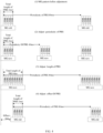
- pattern # 24/25 is introduced for PRS measurement, mainly considering that the required MGL will be relatively great when the number of repetitions of the PRS is relatively great.
- Ri represents a maximum ratio of the number of MGs in which the measurement object i can be a to-be-measured object to the number of MGs in which the measurement object i can be a to-be-measured object and which is not used for a long-periodicity PRS measurement.
- K intra and K inter are determined by the parameter measGapSharingScheme. See Table 2 below. Table 2 measGapSharingScheme Value of X (%) '00' Equalization scheme '01' 25 '10' 50 '11' 75 Here measGapConfig and measGapSharingConfig can be configured through MeasConfig.
- the PRS measurement is limited to be performed only in an MG, and the measurement time of a PRS needs to consider parameters such as a periodicity and a time domain offset of each of the PRS and the MG.
- the periodicity of the MG is much greater than the periodicity of the PRS, there may be a lot of PRSs that fall outside the MG and cannot be measured, resulting in PRS waste.
- the periodicity of the MG is far smaller than the periodicity of the PRS, too frequent MGs will affect the normal uplink and downlink data transmission of a LTE.
- FIG. 3 is a schematic interaction diagram of a wireless communication method 200 according to an embodiment of the present disclosure. As shown in FIG. 3 , the method 300 including the following.
- first information is transmitted by a network device to a terminal device in response to a PRS configuration being changed.
- the first information is used by the terminal device for determining an adjusted MG related configuration.
- the number of terminal devices of the embodiment of the present disclosure may be one or more.
- a change in the PRS configuration may be initiated by a terminal device (UE-initiated).
- the terminal device may transmit a first request to the network device.
- the first request is used for requesting the network device to adjust the PRS configuration.
- the first request may include the PRS configuration required by the terminal device.
- the terminal device may transmit a second request to the network device.
- the second request is used for requesting the network device to adjust the PRS configuration and the MG related configuration.
- the second request may include the PRS configuration required by the terminal device and/or the MG related configuration required by the terminal device.
- the change in the PRS configuration may be initiated by a network device (Network-initiated).
- the network device may transmit a third signaling to the terminal device.
- the third signaling is used for the network device to adjust the PRS configuration of at least one terminal device.
- the third signaling may include the PRS configuration adjusted by the network device.
- the network device may adjust the PRS configuration of a terminal device or a group of terminals. That is, the adjustment of the PRS configuration triggered by the network device may be granular on a per UE or per LTE group basis.
- the network device may transmit a fourth signaling.
- the fourth signaling is used for the network device to adjust the PRS configuration of the terminal device in a cell corresponding to the network device.
- the fourth signaling may be a broadcast message, which may include an adjusted PRS configuration.
- the network device may adjust the PRS configuration of all terminal devices in the cell. That is, the adjustment of the PRS configuration triggered by the network device may be cell-granular.
- the PRS configuration may include related configurations of the PRS measurement, which is not limited herein.
- the PRS configuration includes at least one of: whether a PRS is transmitted; a number of frequency layers of the PRS; a length of the PRS in each frequency layer; a bandwidth of the PRS in each frequency layer; a number of TRPs transmitting the PRS in each frequency layer; a transmission periodicity of the PRS; a number of repetitions of the PRS; a number of symbols occupied by the PRS in each frequency layer; a length of the PRS; or a length of PRS resource.
- it may further include a PRS configuration added in the evolution of standards, such as a PRS aggregation level or a PRS aggregation configuration.
- different PRS configurations may be distinguished into different PRS transmitting levels, also known as PRS transmission levels.
- PRS transmission levels may correspond to different PRS parameter ranges.
- PRS transmission levels are distinguished according to whether the bandwidth of the PRS is greater than X (the unit may be RB, MHz, etc.).
- a bandwidth of the PRS being greater than X may correspond to one PRS transmission level, and a bandwidth of the PRS being smaller than or equal to X corresponds to another PRS transmission level.
- PRS transmission levels are distinguished according to whether the length of the PRS is greater than Y (the unit may be ms or the number of slots, etc.).
- a length of the PRS being greater than Y may correspond to one PRS transmission level, and a bandwidth of the PRS being smaller than or equal to Y corresponds to another PRS transmission level.
- different PRS transmission levels may also be distinguished according to at least two PRS parameters.
- the at least two PRS parameters may include at least two parameters in the PRS configuration of the example described above.
- embodiments of the present disclosure do not limit the number of PRS transmission levels.
- two or more PRS transmission levels may be distinguished according to different PRS configurations, which is not limited by the present disclosure.
- the network device when the PRS configuration changes, the network device adjusts the MG related configuration, thereby improving the measurement efficiency of the PRS.
- the MG related configuration may include any configuration related to the PRS measurement, or may further include configurations related to the PRS measurement that are newly introduced in the evolution of standards, which is not limited by embodiments of the present disclosure.
- a measurement window is introduced for the PRS measurement (similar to an SS/PBCH block measurement timing configuration (SMTC) of a Synchronization Signal Block (SSB) measurement)
- the MG related configuration may further include the measurement window configuration corresponding to the PRS measurement (P-MTC).
- the MG related configuration includes at least one of: an MG pattern configuration; an MG sharing mechanism configuration; or a measurement priority configuration for a PRS in an MG.
- the MG pattern configuration may include the length of the MG, i.e. MGL, and the periodicity of the MG, i.e. MGRP, or may further include parameters newly introduced in the evolution of standards, such as the start position offset of the measurement gap, i.e. gapoffset, etc.
- the MG sharing mechanism configuration may include the parameter measGapSharingScheme, or the Carrier Specific Scaling Factor (CSSF), and other related configurations, or may include a sharing mechanism for PRS and other RRM measurements newly introduced in the standard evolution, which is not limited by the present disclosure.
- CSSF Carrier Specific Scaling Factor
- the MG related configuration may further include the measurement gap configuration, i.e. measGapConfig.
- the network device can improve the measurement efficiency of the PRS by adjusting measGapConfig.
- the MG configuration may include at least one of:
- the MG configuration may further include parameters newly introduced in the evolution of standards, which is not limited thereto.
- an adjustment range of the PRS configuration needs to consider PRS processing capability of the terminal device, thereby avoiding excessive increase of the number of PRSs and improving the measurement efficiency of the PRS.
- the PRS processing capability of the terminal device may include capabilities such as the maximum measurement bandwidth supported by the terminal device, the number of frequency layers of the PRS, the number of TRPs, the maximum length of the PRS that can be processed by the terminal device, or the maximum number of PRS resources that can be processed within each slot.
- a limiting condition of the adjustment of the PRS configuration may take into account the weakest of all receiving devices in processing capacity, which is beneficial to ensure that all receiving devices can receive signals based on the adjusted PRS configuration.
- the limiting condition of the adjustment of the PRS configuration may take into account the strongest of all receiving devices in processing capacity, which is beneficial to ensure that the receiving device with the strongest processing capability can receive the PRS, and other receiving devices can truncate the PRS before receiving.
- the limiting condition of the adjustment of the PRS configuration may take into account the median or average of processing capacities of all receiving devices, which is beneficial to guarantee PRS receiving performance of most receiving devices.
- the above embodiment only takes the length of the single PRS as an example, which can also be replaced by other PRS configurations, such as the bandwidth of the PRS, the number of frequency layers, the number of TRPs, etc. That is, other PRS configurations should not exceed the processing capacity of the terminal device, and the measurement periodicity of the PRS should not be smaller than the time required by the terminal device to process the PRS, etc.
- the adjustment range of the PRS configuration needs to take into account the MG pattern supported by the terminal device.
- the length of the PRS should preferably not exceed the maximum value of the MGL. Therefore, an excessive increase in the number of PRS can be avoided, and the measurement efficiency of PRSs can be improved.
- the maximum MGL is 6ms
- the length of the PRS configured by the network device should not exceed the MGL, otherwise it will lead to the waste of the PRS outside the MG.
- the requested length of the PRS should not exceed the MGL.
- the network device when the network device adjusts the PRS configuration, it needs to consider the MG pattern of the target receiving device of the PRS configuration to ensure the receiving performance of the adjusted PRS configuration.
- a limiting condition of the adjustment of the PRS configuration may take into account the minimum value of the MGL of all receiving devices, which is beneficial to ensure that all receiving devices can receive signals according to the adjusted PRS configuration.
- the limiting condition of the adjustment of the PRS configuration may take into account the maximum value of the MGL of all receiving devices, which is beneficial to ensure that the receiving device with the strongest processing capability can receive the PRS, and other receiving devices can truncate the PRS before receiving.
- the limiting condition of the adjustment of the PRS configuration may take into account the median or average value of the MGL of all receiving devices, which is beneficial to guarantee PRS receiving performance of most receiving devices while taking into account the PRS efficiency.
- the first information may be transmitted via any downlink signaling which the network device and the terminal device communicate.
- the first information is transmitted by at least one of: Radio Resource Control, RRC, signaling; a Media Access Control, MAC, Control Element, CE; or Downlink Control Information, DCI.
- RRC Radio Resource Control
- MAC Media Access Control
- CE Control Element
- DCI Downlink Control Information
- the first information is carried by a first signaling.
- the first signaling is feedback signaling of the network device for the first request transmitted by the terminal device.
- the first request may be used for requesting the network device to adjust the PRS configuration and/or the PRS transmission level.
- the first signaling may include at least one of: request acknowledgement information of the PRS transmission level, request acknowledgement information of the PRS configuration, adjustment information of the MG pattern configuration, adjustment information of the MG sharing mechanism, and adjustment information of the measurement priority corresponding to the PRS.
- the first information is carried by a second signaling.
- the second signaling is a feedback signaling of the network device for a second request transmitted by the terminal device, and the second request is used for requesting an adjustment of the PRS configuration and the MG related configuration.
- the second request may be used for requesting the network device to adjust the PRS configuration and/or the PRS transmission level, and may also requesting the network device to adjust at least one of: the MG pattern configuration, the MG sharing mechanism configuration, or the measurement priority configuration for the PRS.
- the second signaling may include at least one of: request acknowledgement information of the PRS transmission level, request acknowledgement information of the PRS configuration, adjustment information of the MG pattern configuration, adjustment information of the MG sharing mechanism, and adjustment information of the measurement priority corresponding to the PRS.
- the first information is carried by a third signaling.
- the third signaling is used by the network device for adjusting the PRS configuration of the terminal device.
- the third signaling may include at least one of: adjustment information of the MG pattern configuration, adjustment information of the MG sharing mechanism, and adjustment information of the measurement priority corresponding to the PRS.
- the signaling for carrying the first information is collectively referred to as an adjustment signaling for ease of description and illustration.
- the first information may include the adjusted MG related configuration.
- part of the MG related configuration may be changed. For example, only the MG pattern configuration changes, or only the MGL in the MG pattern configuration changes, etc. Alternatively, all of the MG related configuration may be changed, which is not limited in the present disclosure.
- the first information may include only the changed part of MG related configuration. For example, if only the MGL is changed, the first information may include only the changed MGL.
- the first information includes an adjustment amount of the adjusted MG related configuration relative to an MG related configuration before adjustment.
- the first information may include an adjustment amount of the changed part of MG related configuration relative to the MG related configuration before the adjustment.
- the first information may only include an adjustment amount of the changed MGL relative to the MGL before the change.
- the first information includes at least one of:
- the adjustment amount of the parameter corresponding to the MG sharing mechanism configuration may include the adjustment amount of measGapSharingScheme. For example, when adjusted from '00' to '01' in Table 1, the adjustment amount may be 1.
- the adjustment amount may be a difference between the adjusted MG related configuration and the MG related configuration before adjustment, or may also be a ratio of the adjusted MG related configuration to the MG related configuration before adjustment.
- the value of K1 is one of ⁇ 2, 4, 8, 1/2, 1/4, 1/8 ⁇ .
- K1 when the value of K1 is greater than 1, it means that the periodicity of the MG is increased, and when the value of K1 is smaller than 1, it means that the periodicity of the MG is decreased.
- the first information may include a second adjustment amount K2, and the second adjustment amount K2 may be a numerical relationship between the adjusted MGL (denoted as MGL_new) and the MGL before adjustment (denoted as MGL_old).
- K2 may be positive, negative, or 0, so that when determining the adjusted MGL, the MGL before adjustment and K2 may be directly added. In other embodiments, K2 may be positive or 0, in which case a further indication is required of whether to increase or decrease the adjustment amount on the basis of the MGL before adjustment. The above implementation is also applicable to other adjustment amounts.
- the value of K2 may be one of a set of adjustment amounts.
- the set of adjustment amounts may include sets ⁇ -1*S, S ⁇ , ⁇ S, 0 ⁇ , or ⁇ -1*S, S, 0 ⁇ .
- the set S may be ⁇ 0.5, 1, 1.5, 2, 2.5, 3, 4, 4.5, 6, 6.5, 7, 8.5, 10, 14, 14.5, 16, 16.5, 17, 18.5 ⁇ .
- the first information may include a third adjustment amount K3, and the third adjustment amount K3 may be a numerical relationship between the adjusted gapoffset (offset_new) and the gapoffset before adjustment.
- gapoffset_new gapoffset old + K3.
- K3 positive, it means that gapoffset increases; when K3 is negative, it means that gapoffset decreases.
- a format of the adjustment signaling may be an adjustment object and an adjustment amount.
- MGRP_new K1 ⁇ MGRP_old.
- the adjusted MG sharing mechanism configuration may be indicated by a difference value.
- the adjusted measurement priority corresponding to the PRS may be indicated by a difference value.
- the adjusted measurement priority is 1.
- the PRS configuration before adjustment corresponds to the lowest PRS transmission level.
- the PRS transmission level needs to be upgraded, and correspondingly, the MG pattern configuration needs to be adjusted. In one feasible implementation, only the parts that need to be adjusted are indicated on the basis of the MG pattern old.
- the PRS transmission frequency is increased and the PRS transmission periodicity is changed to 40ms.
- the MGRP also needs to be adjusted correspondingly.
- the MGL needs to be correspondingly increased.
- the first information includes at least one of:
- the configuration index corresponding to the MG pattern configuration is used for indicating an order position of the MG pattern configuration in an MG pattern configuration sequence.
- the MG pattern configuration sequence is predefined or configured by the network device.
- a configuration index corresponding to the MG sharing mechanism configuration is used for indicating an order position of the MG sharing mechanism configuration in an MG sharing mechanism configuration sequence.
- the MG sharing mechanism configuration sequence is predefined or configured by a network device.
- the MG pattern configuration sequence is ⁇ MG pattern 0, MG pattern 1, MG pattern 2, MG pattern 3, ... ⁇
- the first information is used for indicating a relative relationship between the adjusted MG pattern configuration and the MG pattern configuration before adjustment in this sequence.
- the first information may indicate that the adjustment object is the MG pattern configuration, and the adjustment amount is an addition of 1, then the adjusted MG pattern configuration is an MG pattern 2.
- the first information can indicate that the adjustment object is an MG pattern configuration and the adjustment amount is a decreasing of 1, then the adjusted MG pattern configuration is an MG pattern 0.
- the MGRPs corresponding to the above MG patterns are the same, and the MGLs and the levels are in an descending order.
- the first information indicates that the MGL is adjusted according to a change in the PRS configuration. For example, if MG pattern # 8 is currently used, and the first information indicates that the MGL is promoted by one level, then the adjusted MG pattern is MG pattern # 14; Or, if the MGLis reduced by two levels, the adjusted MG pattern is MG pattern # 3.
- the MG sharing mechanism configuration sequence is ⁇ sharingScheme_A, sharingScheme_B ⁇
- the first information is used for indicating the relative relationship between the MG sharing mechanism configuration before adjustment and the adjusted MG sharing mechanism configuration in this sequence.
- the MG sharing mechanism configuration before adjustment is sharingScheme_A
- the first information indicates that the MG sharing mechanism needs to be switched (or indicates that the MG sharing mechanism configuration is added by 1), which means that the adjusted MG sharing mechanism is sharingScheme_B.
- the method 300 further includes: determining, by the network device based on an adjusted PRS configuration, a PRS transmission level corresponding to the adjusted PRS configuration; and determining the adjusted MG related configuration based on the PRS transmission level corresponding to the adjusted PRS configuration, and generating the first information based on the adjusted MG related configuration.
- different PRS configurations can be associated with different PRS transmission levels, and the network device may determine the PRS transmission level corresponding to the adjusted PRS configuration based on the adjusted PRS configuration, and further determine the adjusted MG related configuration based on the PRS transmission level.
- the network device may determine the first information based on the PRS transmission level corresponding to the adjusted PRS configuration and an association relationship between the PRS transmission level and the MG related configuration.
- the terminal device may determine the adjusted MG related configuration based on the PRS transmission level corresponding to the adjusted PRS configuration in combination with the association relationship, and further transmit the first information to the terminal device for the terminal device to determine the adjusted MG related configuration.
- the association relationship between the PRS transmission level and the MG related configuration includes at least one of :
- the network device may determine the adjusted MG pattern configuration based on the PRS transmission level corresponding to the adjusted PRS configuration in combination with the association relationship between the PRS transmission level and the MG pattern configuration.
- the network device may determine the adjusted MG sharing mechanism configuration based on the PRS transmission level corresponding to the adjusted PRS configuration in combination with the association relationship between the PRS transmission level and the MG sharing mechanism configuration.
- the network device may determine the adjusted measurement priority of the PRS based on the PRS transmission level corresponding to the adjusted PRS configuration in combination with the association relationship between the PRS transmission level and the measurement priority corresponding to the PRS.
- the association relationship between the PRS transmission level and the MG pattern configuration may include:
- the MG pattern is adjusted from the MG pattern # 9 to the MG pattern # 1 according to the association relationship.
- the network device determines the adjusted MG pattern based on the adjusted PRS configuration. Similarly, the terminal device may also determine the adjusted MG pattern based on the adjusted PRS configuration.
- different PRS parameter ranges of the PRS configuration correspond to different MG patterns.
- the network device may configure parameter values for determining different PRS parameter ranges. That is, the network device may configure a division mode of the PRS parameter ranges of the PRS configuration. Or the parameter values may be predefined. That is, the division mode of the PRS parameter ranges of the PRS configuration may be predefined.
- the embodiment is described by taking the network device configuring the parameter values as an example, but the present disclosure is not limited thereto.
- embodiments of the present disclosure do not limit the number of PRS parameter ranges of the PRS configuration.
- different PRS configurations may be divided into two PRS parameter ranges according to the length of the PRS, or different PRS configurations may be divided into three PRS parameter ranges according to the periodicity of the PRS, etc.
- embodiments of the present disclosure do not limit to the PRS parameters used to divide the PRS parameter ranges.
- the PRS parameter ranges may be divided according to the length of the PRS, or according to the periodicity of the PRS, or according to other PRS parameters, which is not limited by the present disclosure.
- a length of a PRS greater than Y corresponds to a first PRS parameter range
- a length of a PRS smaller than or equal to Y corresponds to a second PRS parameter range.
- the first PRS parameter range corresponds to the MG pattern # 1
- the second PRS parameter range corresponds to the MG pattern # 8.
- a length of a PRS greater than Y2 corresponds to a first PRS parameter range
- a length of a PRS greater than Y1 and smaller than or equal to Y2 corresponds to a second PRS parameter range
- a length of a PRS smaller than or equal to Y1 corresponds to a third PRS parameter range.
- the first PRS parameter range corresponds to the MG pattern # 24
- the second PRS parameter range corresponds to the MG pattern # 5
- the second PRS parameter range corresponds to MG the pattern # 9.
- the network device may determine the PRS parameter range to which the adjusted PRS configuration belongs based on the adjusted PRS configuration in combination with the parameter values for determining different PRS parameter ranges (for example, the aforementioned Y, Y1, or Y2), and further determine the adjusted MG pattern configuration based on the corresponding relationship between the PRS parameter range corresponding to the adjusted PRS configuration and the MG pattern.
- the PRS parameter range to which the adjusted PRS configuration belongs based on the adjusted PRS configuration in combination with the parameter values for determining different PRS parameter ranges (for example, the aforementioned Y, Y1, or Y2), and further determine the adjusted MG pattern configuration based on the corresponding relationship between the PRS parameter range corresponding to the adjusted PRS configuration and the MG pattern.
- association relationship between the PRS transmission level and the MG sharing mechanism configuration may include:
- the network device determines the adjusted MG sharing mechanism based on the adjusted PRS configuration. Similarly, the terminal device may also determine the adjusted MG sharing mechanism based on the adjusted PRS configuration.
- different PRS parameter ranges of the PRS configuration correspond to different MG sharing mechanisms.
- a length of the PRS greater than Y corresponds to the first PRS parameter range
- a length of the PRS smaller than or equal to Y corresponds to the second PRS parameter range.
- a length of the PRS greater than Y2 corresponds to a first PRS parameter range
- a length of the PRS greater than Y1 and smaller than or equal to Y2 corresponds to a second PRS parameter range
- a length of the PRS smaller than or equal to Y1 corresponds to a third PRS parameter range.
- the network device may determine the PRS parameter range to which the adjusted PRS configuration belongs based on the adjusted PRS configuration in combination with the parameter values for determining different PRS parameter ranges (for example, the aforementioned Y, Y1, or Y2), and further determine the adjusted MG sharing mechanism based on a corresponding relationship between the PRS parameter range corresponding to the adjusted PRS configuration and the MG sharing mechanism.
- the PRS parameter range to which the adjusted PRS configuration belongs based on the adjusted PRS configuration in combination with the parameter values for determining different PRS parameter ranges (for example, the aforementioned Y, Y1, or Y2), and further determine the adjusted MG sharing mechanism based on a corresponding relationship between the PRS parameter range corresponding to the adjusted PRS configuration and the MG sharing mechanism.
- the association relationship between the PRS transmission level and the measurement priority of the PRS may include:
- the measurement priority is the PRS transmission level 3 > the PRS transmission level 2 > the PRS transmission level 1.
- only the PRS resource with a high priority may be measured according to the measurement priority order.
- different measurement priorities may correspond to different PRS configuration ranges.
- the network device determines the adjusted measurement priority of the PRS based on the adjusted PRS configuration. Similarly, the terminal device may also determine the adjusted measurement priority of the PRS based on the adjusted PRS configuration.
- different PRS configuration ranges of the PRS configuration correspond to different measurement priorities.
- a length of the PRS greater than Y corresponds to the first PRS parameter range
- the length of the PRS smaller than or equal to Y corresponds to the second PRS parameter range.
- the first PRS parameter range corresponds to the highest measurement priority
- the second PRS parameter range corresponds to the lowest measurement priority.
- the length of the PRS greater than Y2 corresponds to the first PRS parameter range
- the length of the PRS greater than Y1 and smaller than or equal to Y2 corresponds to the second PRS parameter range
- the length of the PRS smaller than or equal to Y1 corresponds to the third PRS parameter range.
- the first PRS parameter range corresponds to the highest measurement priority
- the second PRS parameter range corresponds to the medium measurement priority
- the third PRS parameter range corresponds to the lowest measurement priority.
- the network device may determine the PRS parameter range to which the adjusted PRS configuration belongs based on the adjusted PRS configuration in combination with the parameter values for determining different PRS parameter ranges, and further determine the adjusted measurement priority based on the corresponding relationship between the PRS parameter range corresponding to the adjusted PRS configuration and the measurement priority.
- the terminal device may also determine the adjusted MG related configuration based on the adjusted PRS configuration.
- the specific implementation refers to the related implementation of determining the adjusted MG related configuration by the network device based on the adjusted PRS configuration, which will not be repeated here for the sake of brevity.
- the terminal device measures the PRS based on the adjusted measurement priority corresponding to the PRS.
- the terminal device measures PRSs based on a measurement capability of the terminal device in an descending order of measurement priorities corresponding to the PRSs.
- the terminal device measures no PRS with low measurement priority, when the terminal device is incapable of measuring all PRSs based on the measurement capability of the terminal device. For example, if the measurement capability of the terminal device supports the measurement of two PRS resources and the adjusted PRS configuration includes three PRS resources, the terminal device can only measure two PRS resources with high measurement priorities and discard the PRS with the lowest measurement priority.
- the method 300 further includes the following.
- the network device transmits first indication information to the terminal device.
- the first indication information is used for indicating whether the terminal device is allowed to adjust an MG related configuration based on a PRS transmission level.
- the first indication information may be used for indicating at least one of:
- the terminal device may adjust the MG related configuration based on the transmission level corresponding to the adjusted PRS configuration, when the first indication information indicates that the terminal device is allowed to adjust the MG related configuration based on the PRS transmission level.
- the terminal device may adjust the MG pattern configuration based on the transmission level corresponding to the adjusted PRS configuration, when the first indication information indicates that the terminal device is allowed to adjust the MG pattern configuration based on the PRS transmission level.
- the terminal device may adjust the MG sharing mechanism configuration based on the transmission level corresponding to the adjusted PRS configuration, when the first indication information indicates that the terminal device is allowed to adjust the MG sharing mechanism configuration based on the PRS transmission level.
- the terminal device may adjust the measurement priority corresponding to the PRS based on the transmission level of the adjusted PRS configuration, when the first indication information indicates that the terminal device is allowed to adjust the measurement priority corresponding to the PRS based on the PRS transmission level.
- whether the network device allows the terminal device to adjust the MG pattern configuration based on the PRS transmission level, adjust the MG sharing mechanism configuration based on the PRS transmission level, and adjust the measurement priority corresponding to the PRS based on the PRS transmission level may be indicated by same information or may also be indicated by different information, which is not limited in the present disclosure.
- the adjustment information may be transmitted to the terminal device by one signaling or may also be transmitted to the terminal device by a plurality of signalings, which is not limited herein.
- the method further includes the following.
- the network device receives second indication information transmitted by the terminal device.
- the second indication information is used for indicating whether the terminal device is capable of adjusting an MG related configuration based on a PRS transmission level.
- the network device may instruct the terminal device to adjust the MG related configuration based on the PRS transmission level, when the second indication information indicates that the terminal device is capable of adjusting the MG related configuration based on the PRS transmission level.
- the second indication information is used for indicating at least one of:
- the second indication information may be reported to the network device together with capability-related information as the terminal device reports the capability-related information to the network device.
- the method 300 further includes the following.
- the network device transmits third indication information to the terminal device.
- the third indication information is used for indicating a determination mode of a PRS transmission level.
- the network device may configure the aforementioned PRS parameters Y1 and Y2 to the terminal device.
- the length of the PRS greater than Y2 corresponds to the PRS transmission level 1
- the length of the PRS greater than Y1 and smaller than or equal to Y2 corresponds to the PRS transmission level 2
- the length of the PRS smaller than or equal to Y1 corresponds to the PRS transmission level 3.
- the first indication information, the second indication information, and the third indication information may be carried by existing signaling or may be newly added signaling, which is not limited in embodiments of the present disclosure.
- the network device can transmit the first information to the terminal device, and the first information is used for the terminal device to determine the changed MG related configuration.
- the terminal device can perform the PRS measurement based on the changed MG related configuration, which is beneficial to improving the measurement efficiency of the PRS.
- FIG. 5 is a schematic flowchart of a wireless communication method 200 according to an embodiment of the present disclosure. As shown in FIG. 5 , the method 200 including the following.
- the terminal device determines the adjusted MG related configuration based on the adjusted PRS configuration.
- the PRS configuration includes at least one of: whether a PRS is transmitted; a number of frequency layers of the PRS; a length of the PRS in each frequency layer; a bandwidth of the PRS in each frequency layer; a number of TRPs transmitting the PRS in each frequency layer; a transmission periodicity of the PRS; a number of repetitions of the PRS; or a number of symbols occupied by the PRS in each frequency layer.
- it may include PRS configurations newly introduced in the evolution of standards, such as PRS aggregation level or PRS aggregation configuration, etc. The present disclosure is not limited thereto.
- the MG related configuration includes at least one of: an MG pattern configuration; an MG sharing mechanism configuration; or a measurement priority configuration for a PRS in an MG.
- the method 200 further includes:
- said determining the adjusted MG related configuration based on the PRS transmission level corresponding to the adjusted PRS configuration includes:
- the association relationship between the PRS transmission level and the MG related configuration includes at least one of:
- the method further includes: receiving, by the terminal device, first indication information transmitted by the network device.
- the first indication information is used for indicating whether the terminal device is allowed to adjust an MG related configuration based on the PRS transmission level.
- the method further includes: determining, by the terminal device in response to the first indication information indicating that the terminal device is allowed to adjust the MG related configuration based on the PRS transmission level, the adjusted MG related configuration based on the PRS transmission level corresponding to the adjusted PRS configuration.
- the method further includes: transmitting, by the terminal device, second indication information to the network device.
- the second indication information is used for indicating whether the terminal device is capable of adjusting an MG related configuration based on a PRS transmission level.
- the method further includes: determining, by the terminal device in response to the second indication information indicating that the terminal device is capable of adjusting the MG related configuration based on the PRS transmission level, the adjusted MG related configuration based on the PRS transmission level corresponding to the adjusted PRS configuration.
- the method further includes: receiving, by the terminal device, third indication information transmitted by the network device.
- the third indication information is used for indicating a determination mode of a PRS transmission level.
- the method 200 further includes: measuring, by the terminal device, a PRS based on an adjusted measurement priority corresponding to an PRS.
- said measuring, by the terminal device, the PRS based on the adjusted measurement priority corresponding to the PRS includes: measuring, by the terminal device, PRSs based on a measurement capability of the terminal device in an descending order of measurement priorities corresponding to the PRSs.
- said measuring, by the terminal device, the PRSs based on the measurement capability of the terminal device in accordance with the measurement priorities corresponding to the PRSs includes: measuring, by the terminal device, no PRS with low measurement priority when the terminal device is incapable of measuring all PRSs based on the measurement capability of the terminal device.
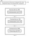
- FIG. 6 is a schematic block diagram of a network device 400 according to an embodiment of the present disclosure.
- the network device 400 includes: a communication unit 410 configured to transmit first information to a terminal device in response to a PRS configuration being changed. The first information is used by the terminal device for determining an adjusted MG related configuration.
- the PRS configuration includes at least one of: whether a PRS is transmitted; a number of frequency layers of the PRS; a length of the PRS in each frequency layer; a bandwidth of the PRS in each frequency layer; a number of TRPs transmitting the PRS in each frequency layer; a transmission periodicity of the PRS; a number of repetitions of the PRS; or a number of symbols occupied by the PRS in each frequency layer.
- it may include PRS configurations newly introduced in the evolution of standards, such as PRS aggregation level or PRS aggregation configuration, etc. The present disclosure is not limited thereto.
- the MG related configuration includes at least one of: an MG pattern configuration; an MG sharing mechanism configuration; or a measurement priority configuration for a PRS in an MG.
- the first information is transmitted by at least one of: RRC signaling; an MAC CE; or DCI.
- the first information is carried by a first signaling.
- the first signaling is a feedback signaling of the network device for a first request transmitted by the terminal device.
- the first request is used for requesting an adjustment to the PRS configuration.
- the first information is carried by a second signaling.
- the second signaling is a feedback signaling of the network device for a second request transmitted by the terminal device.
- the second request is used for requesting an adjustment to the PRS configuration and the MG related configuration.
- the first information is carried by a third signaling.
- the third signaling is used by the network device for adjusting the PRS configuration of the terminal device.
- the first information includes an adjustment amount of the adjusted MG related configuration relative to an MG related configuration before adjustment.
- the first information includes at least one of:
- the first information includes at least one of:
- the configuration index corresponding to the MG pattern configuration is used for indicating an order position of the MG pattern configuration in an MG pattern configuration sequence, the MG pattern configuration sequence being predefined or configured by the network device.
- the configuration index corresponding to the MG sharing mechanism configuration is used for indicating an order position of the MG sharing mechanism configuration in an MG sharing mechanism configuration sequence, the MG sharing mechanism configuration sequence being predefined or configured by the network device.
- the network device further includes: a processing unit configured to determine, based on an adjusted PRS configuration, a PRS transmission level corresponding to the adjusted PRS configuration; and determine the first information based on the PRS transmission level corresponding to the adjusted PRS configuration.
- the processing unit is further configured to determine the first information based on the PRS transmission level corresponding to the adjusted PRS configuration and an association relationship between the PRS transmission level and the MG related configuration.
- the association relationship between the PRS transmission level and the MG related configuration includes at least one of:
- the communication unit 410 is further configured to transmit first indication information to the terminal device.
- the first indication information is used for indicating whether the terminal device is allowed to adjust an MG related configuration based on a PRS transmission level.
- the communication unit 410 is further configured to receive second indication information transmitted by the terminal device.
- the second indication information is used for indicating whether the terminal device is capable of adjusting an MG related configuration based on a PRS transmission level.
- the communication unit 410 is further configured to transmit third indication information to the terminal device.
- the third indication information is used for indicating a determination mode of a PRS transmission level.
- the first information includes the adjusted MG related configuration.
- the communication unit may be a communication interface or a transceiver, or an input-output interface of a communication chip or a system-on-chip.
- the processing unit may be one or more processors.
- terminal device 400 may correspond to the terminal device in the method embodiments of the present disclosure.
- the above and other operations and/or functions of individual unit in the network device 400 are respectively for implementing the corresponding process performed by the network device in the method 300 shown in FIG. 3 , which will not be repeated for the sake of brevity.
- FIG. 7 is a schematic block diagram of a terminal device according to an embodiment of the present disclosure.
- the terminal device 500 of FIG. 7 includes: a communication unit 510 configured to receive first information transmitted by a network device in response to a PRS configuration being changed. The first information is used by the terminal device for determining an adjusted MG related configuration.
- the PRS configuration includes at least one of: whether a PRS is transmitted; a number of frequency layers of the PRS; a length of the PRS in each frequency layer; a bandwidth of the PRS in each frequency layer; a number of TRPs transmitting the PRS in each frequency layer; a transmission periodicity of the PRS; a number of repetitions of the PRS; or a number of symbols occupied by the PRS in each frequency layer.
- it may include PRS configurations newly introduced in the evolution of standards, such as PRS aggregation level or PRS aggregation configuration, etc. The present disclosure is not limited thereto.
- the MG related configuration includes at least one of: an MG pattern configuration; an MG sharing mechanism configuration; or a measurement priority configuration for a PRS in an MG.
- the first information is transmitted by at least one of: RRC signaling; an MAC CE; or DCI.
- the first information is carried by a first signaling.
- the first signaling is a feedback signaling of the network device for a first request transmitted by the terminal device.
- the first request is used for requesting an adjustment to the PRS configuration.
- the first information is carried by a second signaling.
- the second signaling is a feedback signaling of the network device for a second request transmitted by the terminal device.
- the second request is used for requesting an adjustment to the PRS configuration and the MG related configuration.
- the first information is carried by a third signaling.
- the third signaling is used for the network device to adjust the PRS configuration of the terminal device.
- the second request is used for requesting an adjustment to the PRS configuration and the MG related configuration.
- the first information includes an adjustment amount of the adjusted MG related configuration relative to an MG related configuration before adjustment.
- the first information includes at least one of:
- the first information includes at least one of:
- the configuration index corresponding to the MG pattern configuration is used for indicating an order position of the MG pattern configuration in an MG pattern configuration sequence, the MG pattern configuration sequence being predefined or configured by the network device.
- the configuration index corresponding to the MG sharing mechanism configuration is used for indicating an order position of the MG sharing mechanism configuration in an MG sharing mechanism configuration sequence, the MG sharing mechanism configuration sequence being predefined or configured by the network device.
- the communication unit 510 is further configured to receive first indication information transmitted by the network device.
- the first indication information is used for indicating whether the terminal device is allowed to adjust an MG related configuration based on a PRS transmission level.
- the communication unit 510 is further configured to determine, in response to the first indication information indicating that the terminal device is not allowed to adjust an MG related configuration based on a PRS transmission level, the adjusted MG related configuration based on the first information.
- the communication unit 510 is further configured to transmit second indication information to the network device.
- the second indication information is used for indicating whether the terminal device is capable of adjusting an MG related configuration based on a PRS transmission level.
- the terminal device further include a processing unit configured to determine, in response to the second indication information indicating that the terminal device is incapable of adjusting the MG related configuration based on the PRS transmission level, the adjusted MG related configuration based on the adjusted PRS configuration.
- the communication unit 510 is further configured to receive third indication information transmitted by the network device.
- the third indication information is used for indicating a determination mode of a PRS transmission level.
- the terminal device further includes a processing unit is configured to measure a PRS based on an adjusted measurement priority corresponding to a PRS.
- the processing unit is specifically configured to measure PRSs based on a measurement capability of the terminal device in an descending order of measurement priorities corresponding to the PRSs.
- the processing unit is further configured to measure no PRS with low measurement priority, when the terminal device is incapable of measuring all PRSs based on the measurement capability of the terminal device.
- the communication unit may be a communication interface or a transceiver, or an input-output interface of a communication chip or a system-on-chip.
- the processing unit may be one or more processors.
- terminal device 500 may correspond to the terminal device in the method embodiments of the present disclosure.
- the above and other operations and/or functions of individual unit in the network device 500 are respectively for implementing the corresponding process performed by the network device in the method 300 shown in FIG. 3 , which will not be repeated for the sake of brevity.
- FIG. 8 is a schematic block diagram of a terminal device according to an embodiment of the present disclosure.
- the terminal device 800 of FIG. 8 includes a processing unit 810 configured to determine an adjusted MG related configuration based on an adjusted PRS configuration.
- the PRS configuration includes at least one of: whether a PRS is transmitted; a number of frequency layers of the PRS; a length of the PRS in each frequency layer; a bandwidth of the PRS in each frequency layer; a number of TRPs transmitting the PRS in each frequency layer; a transmission periodicity of the PRS; a number of repetitions of the PRS; or a number of symbols occupied by the PRS in each frequency layer.
- it may include PRS configurations newly introduced in the evolution of standards, such as PRS aggregation level or PRS aggregation configuration, etc. The present disclosure is not limited thereto.
- the MG related configuration includes at least one of: an MG pattern configuration; an MG sharing mechanism configuration; or a measurement priority configuration for a PRS in an MG.
- the processing unit 810 is further configured to: determine a PRS transmission level corresponding to the adjusted PRS configuration based on the adjusted PRS configuration; and determine the adjusted MG related configuration based on the PRS transmission level corresponding to the adjusted PRS configuration.
- the processing unit 810 is further configured to determine the adjusted MG related configuration based on the PRS transmission level corresponding to the adjusted PRS configuration and an association relationship between the PRS transmission level and the MG related configuration.
- the association relationship between the PRS transmission level and the MG related configuration includes at least one of:
- the terminal device further includes a communication unit configured to receive first indication information transmitted by the network device.
- the first indication information is used for indicating whether the terminal device is allowed to adjust an MG related configuration based on the PRS transmission level.
- the processing unit 810 is further configured to determine, in response to the first indication information indicating that the terminal device is allowed to adjust the MG related configuration based on the PRS transmission level, the adjusted MG related configuration based on the PRS transmission level corresponding to the adjusted PRS configuration.
- the terminal device further includes the communication unit configured to transmit second indication information to the network device.
- the second indication information is used for indicating whether the terminal device is capable of adjusting an MG related configuration based on a PRS transmission level.
- the processing unit 810 is further configured to determine, in response to the second indication information indicating that the terminal device is capable of adjusting the MG related configuration based on the PRS transmission level, the adjusted MG related configuration based on the PRS transmission level corresponding to the adjusted PRS configuration.
- the terminal device further includes the communication unit configured to receive third indication information transmitted by the network device.
- the third indication information is used for indicating a determination mode of a PRS transmission level.
- the processing unit 810 is further configured to measure a PRS based on an adjusted measurement priority corresponding to an PRS.
- the processing unit 810 is further configured to measure PRSs based on a measurement capability of the terminal device in an descending order of measurement priorities corresponding to the PRSs.
- the processing unit 810 is specifically configured to measure no PRS with low measurement priority when the terminal device is incapable of measuring all PRSs based on the measurement capability of the terminal device.
- the communication unit may be a communication interface or a transceiver, or an input-output interface of a communication chip or a system-on-chip.
- the processing unit may be one or more processors.
- terminal device 800 may correspond to the terminal device in the method embodiments of the present disclosure.
- the above and other operations and/or functions of individual unit in the network device 800 are respectively for implementing the corresponding process performed by the network device in the method 200 shown in FIG. 5 , which will not be repeated for the sake of brevity.
- FIG. 9 is a schematic block diagram of a communication device 600 according to an embodiment of the present disclosure.
- the communication device 600 shown in FIG. 9 includes a processor 610.
- the processor 610 is configured to invoke and run a computer program from a memory to perform the method according to any one of the embodiments of the present disclosure.
- the communication device 600 may further include a memory 620.
- the processor 610 may invoke and run a computer program from the memory 620 to perform the method according to any one of the embodiments of the present disclosure.
- the memory 620 may be a separate component independent of the processor 610, or may be integrated in the processor 610.
- the communication device 600 may further include a transceiver 630.
- the processor 610 may control the transceiver 630 to communicate with other devices, specifically, to transmit information or data to other devices, or receive information or data transmitted by other devices.
- the transceiver 630 may include a transmitter and a receiver.
- the transceiver 630 may further include one or more antennas.
- the communication device 600 may specifically be a network device according to the embodiment of the present disclosure.
- the communication device 600 may execute corresponding processes implemented by the network device in the method according to any one of the embodiments of the present disclosure. For brevity, details thereof will be omitted herein.
- the communication device 600 may specifically be the mobile terminal/the terminal device any one of the embodiments of the present disclosure.
- the communication device 600 may implement corresponding processes implemented by the terminal device in the method according to any one of the embodiments of the present disclosure. For brevity, details thereof will be omitted herein.
- FIG. 10 is a schematic block diagram of a chip according to an embodiment of the present disclosure.
- a chip 700 includes a processor 710.
- the processor 710 can invoke and run a computer program from a memory to perform the method according to any one of the embodiments of the present disclosure.
- the chip 700 may further include a memory 720.
- the processor 710 may invoke and run a computer program from the memory 720 to perform the method according to any one of the embodiments of the present disclosure.
- the memory 720 may be a separate component independent of the processor 710, or may be integrated in the processor 710.
- the chip 700 may further include an input interface 730.
- the processor 710 can control the input interface 730 to communicate with other devices or chips, specifically, to obtain information or data transmitted by other devices or chips.
- the chip 700 may further include an output interface 740.
- the processor 710 can control the output interface 740 to communicate with other devices or chips, specifically, to output information or data to other devices or chips.
- the chip can be applied to the network device according to any one of the embodiments of the present disclosure.
- the chip can implement corresponding processes implemented by the network device in the method according to any one of the embodiments of the present disclosure. For brevity, details thereof will be omitted herein.
- the chip can be applied to the mobile terminal/terminal device according to the embodiments of the present disclosure, and the chip can implement corresponding processes implemented by the mobile terminal/terminal device in the method according to any one of the embodiments of the present disclosure. For brevity, details thereof will be omitted herein.
- the chip mentioned in the embodiments of the present disclosure may also be referred to as a system-level chip, a system-chip, a chip system, or a system-on-chip.
- the processor may be an integrated circuit chip having signal processing capabilities.
- actions of the above method may be accomplished by an integrated logic circuit in hardware in the processor or by instructions in the form of software.
- the above processor may be a general-purpose processor, a Digital Signal processor (DSP), an Application Specific Integrated Circuit (ASIC), a Field-Programmable Gate Array (FPGA) or other programmable logic devices, a discrete gate or a transistor logic device, or a discrete hardware component.
- DSP Digital Signal processor
- ASIC Application Specific Integrated Circuit
- FPGA Field-Programmable Gate Array
- the method, actions, and logic block diagrams according to any one of the embodiments of the present disclosure may be implemented or performed.
- the general-purpose processor may be a microprocessor, or the processor may further be any conventional processor, etc.
- the actions of the method disclosed in combination with any one of the embodiments of the present disclosure may be directly embodied as performed by a hardware decoding processor or performed by a combination of a hardware module and a software module in a decoding processor.
- the software module may be located in a random memory, a flash memory, a read-only memory, a programmable read-only memory or an electrically erasable programmable memory, a register, and other storage media mature in the art.
- the storage medium is located in the memory.
- the processor reads information in the memory and completes the actions of the above method in combination with the hardware.
- the memory may be a transitory memory or a non-transitory memory, or may include both transitory and non-transitory memories.
- the non-transitory memory may be a Read-Only Memory (ROM), a Programmable ROM (PROM), an Erasable PROM (EPROM), an Electrically EPROM (EEPROM), or a flash memory.
- the transitory memory may be a Random Access Memory (RAM), which serves as an external cache.
- RAM Direct Rambus RAM
- SRAM Static RAM
- DRAM Dynamic RAM
- SDRAM Synchronous DRAM
- DDR SDRAM Double Data Rate SDRAM
- ESDRAM Enhanced SDRAM
- SLDRAM Synch Link DRAM
- DR RAM Direct Rambus RAM
- the above memories are exemplary only, rather than limiting the present disclosure.
- the memory in the embodiment of the present disclosure may also be a Static RAM (SRAM), a Dynamic RAM (DRAM), a Synchronous DRAM (SDRAM), a Double Data Rate SDRAM (DDR SDRAM), an Enhanced SDRAM (ESDRAM), a Synch Link DRAM (SLDRAM), a Direct Rambus RAM (DR RAM) or the like. That is, the memory in the embodiments of the present disclosure is intended to include, but not limited to, these and any other suitable types of memories.
- SRAM Static RAM
- DRAM Dynamic RAM
- SDRAM Synchronous DRAM
- DDR SDRAM Double Data Rate SDRAM
- ESDRAM Enhanced SDRAM
- SLDRAM Synch Link DRAM
- DR RAM Direct Rambus RAM
- An embodiment of the present disclosure also provides a computer readable storage medium for storing a computer program.
- the computer readable storage medium can be applied to the network device in the embodiment of the present disclosure, and the computer program can cause a computer to perform corresponding procedures implemented by the network device in the method according to any one of the embodiments of the present disclosure. Details thereof will be omitted here for simplicity.
- the computer readable storage medium can be applied to the mobile terminal/terminal device in the embodiment of the present disclosure, and the computer program can cause a computer to perform corresponding procedures implemented by the mobile terminal/terminal device in the method according to any one of the embodiments of the present disclosure. Details thereof will be omitted here for simplicity.
- An embodiment of the present disclosure also provides a computer program product including computer program instructions.
- the computer program product can be applied to the network device in the embodiment of the present disclosure, and the computer program instructions can cause a computer to perform corresponding procedures implemented by the network device in the method according to any one of the embodiments of the present disclosure. Details thereof will be omitted here for simplicity.
- the computer program product can be applied to the mobile terminal/terminal device in the embodiment of the present disclosure, and the computer program instructions can cause a computer to perform corresponding procedures implemented by the mobile terminal/terminal device in the method according to any one of the embodiments of the present disclosure. Details thereof will be omitted here for simplicity.
- An embodiment of the present disclosure also provides a computer program.
- the computer program can be applied to the network device in the embodiment of the present disclosure.
- the computer program when executed on a computer, can cause the computer to perform corresponding procedures implemented by the network device in the method according to any one of the embodiments of the present disclosure. Details thereof will be omitted here for simplicity.
- the computer program can be applied to the mobile terminal/terminal device in the embodiment of the present disclosure.
- the computer program when executed on a computer, can cause the computer to perform corresponding procedures implemented by the mobile terminal/terminal device in the method according to any one of the embodiments of the present disclosure. Details thereof will be omitted here for simplicity.
- the disclosed systems, devices, and methods may be implemented in other ways.
- the device embodiments described above are illustrative only.
- the divisions of the units are only divisions based on logical functions, and there may be other divisions in actual implementations.
- more than one unit or component may be combined or integrated into another system, or some features can be ignored or omitted.
- the mutual coupling or direct coupling or communicative connection as shown or discussed may be indirect coupling or communicative connection between devices or units via some interfaces which may be electrical, mechanical, or in any other forms.
- the units described as separate components may or may not be physically separated, and the components shown as units may or may not be physical units, that is, they may be co-located or distributed across a number of network elements. Some or all of the units may be selected according to actual needs to achieve the objects of the solutions of the embodiments.
- the functional units in the embodiments of the present disclosure may be integrated into one processing unit, or alternatively be separate physical modules, or two or more units may be integrated into one unit.
- the computer software product may be stored in a storage medium and contain instructions to enable a computer device, such as a personal computer, a server, or a network device, etc., to perform all or part of the steps of the method described in each of the embodiments of the present disclosure.
- the storage medium may include a Universal Serial Bus flash drive, a mobile hard disk, a Read-Only Memory (ROM), a Random Access Memory (RAM), a magnetic disk, an optical disc, or any other medium capable of storing program codes.
Landscapes
- Engineering & Computer Science (AREA)
- Signal Processing (AREA)
- Computer Networks & Wireless Communication (AREA)
- Physics & Mathematics (AREA)
- General Physics & Mathematics (AREA)
- Radar, Positioning & Navigation (AREA)
- Remote Sensing (AREA)
- Mobile Radio Communication Systems (AREA)
Applications Claiming Priority (1)
| Application Number | Priority Date | Filing Date | Title |
|---|---|---|---|
| PCT/CN2021/071910 WO2022151256A1 (fr) | 2021-01-14 | 2021-01-14 | Procédé de communication sans fil, dispositif terminal et dispositif réseau |
Publications (2)
| Publication Number | Publication Date |
|---|---|
| EP4277334A1 true EP4277334A1 (fr) | 2023-11-15 |
| EP4277334A4 EP4277334A4 (fr) | 2024-03-13 |
Family
ID=82447901
Family Applications (1)
| Application Number | Title | Priority Date | Filing Date |
|---|---|---|---|
| EP21918464.5A Pending EP4277334A4 (fr) | 2021-01-14 | 2021-01-14 | Procédé de communication sans fil, dispositif terminal et dispositif réseau |
Country Status (4)
| Country | Link |
|---|---|
| US (1) | US12587993B2 (fr) |
| EP (1) | EP4277334A4 (fr) |
| CN (1) | CN116569584A (fr) |
| WO (1) | WO2022151256A1 (fr) |
Families Citing this family (3)
| Publication number | Priority date | Publication date | Assignee | Title |
|---|---|---|---|---|
| BR112023020284A2 (pt) * | 2021-03-30 | 2024-01-23 | Interdigital Patent Holdings Inc | Métodos e aparelho para suportar continuidade de serviço de posicionamento |
| US12243359B1 (en) * | 2021-04-05 | 2025-03-04 | Nuro, Inc. | Methods and apparatus for improving vehicle communication network bandwidth |
| CN121751322A (zh) * | 2024-09-26 | 2026-03-27 | 华为技术有限公司 | 通信方法及装置 |
Family Cites Families (15)
| Publication number | Priority date | Publication date | Assignee | Title |
|---|---|---|---|---|
| US5852630A (en) * | 1997-07-17 | 1998-12-22 | Globespan Semiconductor, Inc. | Method and apparatus for a RADSL transceiver warm start activation procedure with precoding |
| CN102595450B (zh) * | 2011-01-10 | 2014-12-24 | 华为技术有限公司 | 测量间隙的配置方法和通信装置 |
| CN104540169B (zh) * | 2011-01-10 | 2018-05-18 | 华为技术有限公司 | 测量间隙的配置方法和通信装置 |
| JP6359815B2 (ja) * | 2013-09-26 | 2018-07-18 | 株式会社Nttドコモ | ユーザ端末、無線基地局及び異周波測定方法 |
| US10009080B2 (en) * | 2016-10-14 | 2018-06-26 | Qualcomm Incorporated | Reference signal measurements |
| US10285156B2 (en) * | 2017-04-09 | 2019-05-07 | Qualcomm Incorporated | Dynamic measurement gap configuration for inter-frequency positioning measurements |
| KR102358569B1 (ko) * | 2017-09-15 | 2022-02-04 | 삼성전자 주식회사 | 광대역 시스템을 위한 이동 통신 방법 및 장치 |
| CN111417189B (zh) * | 2019-01-07 | 2021-08-06 | 中国移动通信有限公司研究院 | 一种定位测量的方法和设备 |
| CN111342943B (zh) | 2019-04-29 | 2021-07-02 | 维沃移动通信有限公司 | Prs资源配置方法、测量间隔配置方法和相关设备 |
| WO2020248261A1 (fr) * | 2019-06-14 | 2020-12-17 | Oppo广东移动通信有限公司 | Procédé et appareil de détermination d'intervalle de mesure, et terminal |
| EP4142337B1 (fr) * | 2020-05-27 | 2024-12-18 | Guangdong Oppo Mobile Telecommunications Corp., Ltd. | Mesures dans un reseau |
| US20230164735A1 (en) * | 2020-08-05 | 2023-05-25 | Vivo Mobile Communication Co., Ltd. | Positioning method and apparatus, and related device |
| US11743752B2 (en) * | 2020-09-14 | 2023-08-29 | Qualcomm Incorporated | Dynamic configuration of measurement gaps |
| CN116250373A (zh) * | 2020-10-13 | 2023-06-09 | 三菱电机株式会社 | 通信系统 |
| KR20230086686A (ko) * | 2020-10-15 | 2023-06-15 | 퀄컴 인코포레이티드 | 업링크 및 다운링크 포지셔닝 자원들의 근접성-기반 우선순위화 |
-
2021
- 2021-01-14 WO PCT/CN2021/071910 patent/WO2022151256A1/fr not_active Ceased
- 2021-01-14 EP EP21918464.5A patent/EP4277334A4/fr active Pending
- 2021-01-14 CN CN202180082142.5A patent/CN116569584A/zh active Pending
-
2023
- 2023-07-11 US US18/350,439 patent/US12587993B2/en active Active
Also Published As
| Publication number | Publication date |
|---|---|
| WO2022151256A1 (fr) | 2022-07-21 |
| EP4277334A4 (fr) | 2024-03-13 |
| US20230362872A1 (en) | 2023-11-09 |
| CN116569584A (zh) | 2023-08-08 |
| US12587993B2 (en) | 2026-03-24 |
Similar Documents
| Publication | Publication Date | Title |
|---|---|---|
| EP3883317B1 (fr) | Procédé de communication sans fil, dispositif terminal et dispositif de réseau | |
| US12414077B2 (en) | Paging message detection method, apparatus, and communication device | |
| EP4184995B1 (fr) | Procédé de communication sans fil, dispositif terminal et dispositif de réseau | |
| US12587993B2 (en) | Wireless communication method, terminal device, and network device | |
| CN114902592B (zh) | 传输初始接入配置信息的方法和装置 | |
| CN112584412B (zh) | 一种波束切换的方法、装置及通信设备 | |
| US12114187B2 (en) | Wireless communication method, terminal device and network device | |
| US11546044B2 (en) | Wireless communication method, terminal device and network device | |
| US11553495B2 (en) | Method and device for sending uplink channel, and method and device for receiving uplink channel | |
| JP2024510324A (ja) | 情報伝送方法、端末デバイス、ネットワークデバイス、チップ和記憶媒体 | |
| US12581398B2 (en) | Wireless communication method, terminal device and network device | |
| US12170980B2 (en) | Wireless communication resource allocation method and apparatus, and communication device | |
| CN117356125A (zh) | 无线通信的方法、终端设备和网络设备 | |
| US20230007682A1 (en) | Data transmission method, terminal device and network device | |
| CN114342532A (zh) | 一种探测参考信号srs周期的配置方法及装置 | |
| CN115428527B (zh) | 数据传输的方法和设备 | |
| US20240244476A1 (en) | Wireless communication method, and devices | |
| CN113765642B (zh) | Harq码本确定方法、终端设备和网络设备 | |
| US12501487B2 (en) | Wireless communication method, terminal device and network device | |
| WO2023141760A1 (fr) | Procédé de communication sans fil, dispositif terminal et dispositif de réseau | |
| EP4607992A1 (fr) | Procédé de communication sans fil, équipement terminal et dispositif de réseau | |
| WO2020133469A1 (fr) | Procédé d'accès aléatoire, dispositif terminal et dispositif de réseau | |
| CN116458210A (zh) | 网络选择的方法、终端设备和网络设备 | |
| CN118044142A (zh) | 无线通信的方法、终端设备和网络设备 |
Legal Events
| Date | Code | Title | Description |
|---|---|---|---|
| STAA | Information on the status of an ep patent application or granted ep patent |
Free format text: STATUS: THE INTERNATIONAL PUBLICATION HAS BEEN MADE |
|
| PUAI | Public reference made under article 153(3) epc to a published international application that has entered the european phase |
Free format text: ORIGINAL CODE: 0009012 |
|
| STAA | Information on the status of an ep patent application or granted ep patent |
Free format text: STATUS: REQUEST FOR EXAMINATION WAS MADE |
|
| 17P | Request for examination filed |
Effective date: 20230809 |
|
| AK | Designated contracting states |
Kind code of ref document: A1 Designated state(s): AL AT BE BG CH CY CZ DE DK EE ES FI FR GB GR HR HU IE IS IT LI LT LU LV MC MK MT NL NO PL PT RO RS SE SI SK SM TR |
|
| REG | Reference to a national code |
Ref country code: DE Ref legal event code: R079 Free format text: PREVIOUS MAIN CLASS: H04W0024020000 Ipc: H04L0005000000 |
|
| A4 | Supplementary search report drawn up and despatched |
Effective date: 20240212 |
|
| RIC1 | Information provided on ipc code assigned before grant |
Ipc: H04W 64/00 20090101ALI20240207BHEP Ipc: H04L 5/00 20060101AFI20240207BHEP |
|
| DAV | Request for validation of the european patent (deleted) | ||
| DAX | Request for extension of the european patent (deleted) |