EP4277866B1 - Système de transport avec courroies de transfert - Google Patents
Système de transport avec courroies de transfert Download PDFInfo
- Publication number
- EP4277866B1 EP4277866B1 EP22701804.1A EP22701804A EP4277866B1 EP 4277866 B1 EP4277866 B1 EP 4277866B1 EP 22701804 A EP22701804 A EP 22701804A EP 4277866 B1 EP4277866 B1 EP 4277866B1
- Authority
- EP
- European Patent Office
- Prior art keywords
- product
- conveyor
- transfer
- section
- outer side
- Prior art date
- Legal status (The legal status is an assumption and is not a legal conclusion. Google has not performed a legal analysis and makes no representation as to the accuracy of the status listed.)
- Active
Links
Images




Classifications
-
- B—PERFORMING OPERATIONS; TRANSPORTING
- B65—CONVEYING; PACKING; STORING; HANDLING THIN OR FILAMENTARY MATERIAL
- B65G—TRANSPORT OR STORAGE DEVICES, e.g. CONVEYORS FOR LOADING OR TIPPING, SHOP CONVEYOR SYSTEMS OR PNEUMATIC TUBE CONVEYORS
- B65G47/00—Article or material-handling devices associated with conveyors; Methods employing such devices
- B65G47/74—Feeding, transfer, or discharging devices of particular kinds or types
- B65G47/84—Star-shaped wheels or devices having endless travelling belts or chains, the wheels or devices being equipped with article-engaging elements
- B65G47/841—Devices having endless travelling belts or chains equipped with article-engaging elements
-
- B—PERFORMING OPERATIONS; TRANSPORTING
- B65—CONVEYING; PACKING; STORING; HANDLING THIN OR FILAMENTARY MATERIAL
- B65G—TRANSPORT OR STORAGE DEVICES, e.g. CONVEYORS FOR LOADING OR TIPPING, SHOP CONVEYOR SYSTEMS OR PNEUMATIC TUBE CONVEYORS
- B65G15/00—Conveyors having endless load-conveying surfaces, i.e. belts and like continuous members, to which tractive effort is transmitted by means other than endless driving elements of similar configuration
- B65G15/10—Conveyors having endless load-conveying surfaces, i.e. belts and like continuous members, to which tractive effort is transmitted by means other than endless driving elements of similar configuration comprising two or more co-operating endless surfaces with parallel longitudinal axes, or a multiplicity of parallel elements, e.g. ropes defining an endless surface
- B65G15/12—Conveyors having endless load-conveying surfaces, i.e. belts and like continuous members, to which tractive effort is transmitted by means other than endless driving elements of similar configuration comprising two or more co-operating endless surfaces with parallel longitudinal axes, or a multiplicity of parallel elements, e.g. ropes defining an endless surface with two or more endless belts
- B65G15/14—Conveyors having endless load-conveying surfaces, i.e. belts and like continuous members, to which tractive effort is transmitted by means other than endless driving elements of similar configuration comprising two or more co-operating endless surfaces with parallel longitudinal axes, or a multiplicity of parallel elements, e.g. ropes defining an endless surface with two or more endless belts the load being conveyed between the belts
-
- B—PERFORMING OPERATIONS; TRANSPORTING
- B65—CONVEYING; PACKING; STORING; HANDLING THIN OR FILAMENTARY MATERIAL
- B65G—TRANSPORT OR STORAGE DEVICES, e.g. CONVEYORS FOR LOADING OR TIPPING, SHOP CONVEYOR SYSTEMS OR PNEUMATIC TUBE CONVEYORS
- B65G17/00—Conveyors having an endless traction element, e.g. a chain, transmitting movement to a continuous or substantially-continuous load-carrying surface or to a series of individual load-carriers; Endless-chain conveyors in which the chains form the load-carrying surface
- B65G17/16—Conveyors having an endless traction element, e.g. a chain, transmitting movement to a continuous or substantially-continuous load-carrying surface or to a series of individual load-carriers; Endless-chain conveyors in which the chains form the load-carrying surface comprising individual load-carriers which are pivotally mounted, e.g. for free-swinging movement
- B65G17/18—Conveyors having an endless traction element, e.g. a chain, transmitting movement to a continuous or substantially-continuous load-carrying surface or to a series of individual load-carriers; Endless-chain conveyors in which the chains form the load-carrying surface comprising individual load-carriers which are pivotally mounted, e.g. for free-swinging movement and move in contact with a guiding surface
-
- B—PERFORMING OPERATIONS; TRANSPORTING
- B65—CONVEYING; PACKING; STORING; HANDLING THIN OR FILAMENTARY MATERIAL
- B65G—TRANSPORT OR STORAGE DEVICES, e.g. CONVEYORS FOR LOADING OR TIPPING, SHOP CONVEYOR SYSTEMS OR PNEUMATIC TUBE CONVEYORS
- B65G17/00—Conveyors having an endless traction element, e.g. a chain, transmitting movement to a continuous or substantially-continuous load-carrying surface or to a series of individual load-carriers; Endless-chain conveyors in which the chains form the load-carrying surface
- B65G17/30—Details; Auxiliary devices
- B65G17/48—Controlling attitudes of load-carriers during movement
-
- B—PERFORMING OPERATIONS; TRANSPORTING
- B65—CONVEYING; PACKING; STORING; HANDLING THIN OR FILAMENTARY MATERIAL
- B65G—TRANSPORT OR STORAGE DEVICES, e.g. CONVEYORS FOR LOADING OR TIPPING, SHOP CONVEYOR SYSTEMS OR PNEUMATIC TUBE CONVEYORS
- B65G47/00—Article or material-handling devices associated with conveyors; Methods employing such devices
- B65G47/52—Devices for transferring articles or materials between conveyors i.e. discharging or feeding devices
-
- B—PERFORMING OPERATIONS; TRANSPORTING
- B65—CONVEYING; PACKING; STORING; HANDLING THIN OR FILAMENTARY MATERIAL
- B65G—TRANSPORT OR STORAGE DEVICES, e.g. CONVEYORS FOR LOADING OR TIPPING, SHOP CONVEYOR SYSTEMS OR PNEUMATIC TUBE CONVEYORS
- B65G47/00—Article or material-handling devices associated with conveyors; Methods employing such devices
- B65G47/52—Devices for transferring articles or materials between conveyors i.e. discharging or feeding devices
- B65G47/66—Fixed platforms or combs, e.g. bridges between conveyors
Definitions
- the invention relates generally to power-driven conveyors and more particularly to conveyors having transfer belts facilitating transfer between end-to-end conveyors.
- Conveyors such as endless conveyor belts trained around reversing elements at each end, or roller conveyors comprising a series of rotatable rollers for moving objects, are often arranged end-to-end with a gap between the downstream end of an upstream conveyor and the upstream end of a downstream conveyor. Bridging the gap can be problematic for certain articles.
- Various transfer mechanisms such as transfer belts, transfer plates and transfer platforms have been used to provide a smoother product transfer between the confronting ends of the two conveyors.
- JP S 52 117791 A discloses a holding belt for a hydraulic automatic pearl oyster cleaner.
- a transfer conveyor (see Fig. 2 ) suitable for transferring product (6), comprising: a frame (5) configured to overlay a transfer gap between a first product conveyor (3) and a second product conveyor (4), the frame comprising a first outer side wall having a first section that extends along a first side of the first product conveyor, and a third section that bridges the transfer gap, a second outer side wall having a first section that extends along a second side of the first product conveyor, and a third section that bridges the transfer gap, and a transfer plate (5) extending between the third sections of the first and second outer side walls, the transfer plate bridging the transfer gap.
- a conveyor system includes a transfer conveyor for gently transferring products between two product conveyors.
- the transfer conveyor comprises a frame and two transfer conveyor belts nestled around the product conveyors for lifting and transferring product over a transfer gap between the product conveyors.
- Each transfer conveyor belt comprises a series of modules arranged in an endless loop and containing a plurality of movable lifting flaps for carrying the product in the transfer region.
- a transfer conveyor for transferring product comprises a frame configured to overlay a transfer gap between a first product conveyor and a second product conveyor.
- the frame comprises a first outer side wall having a first section that extends along a first side of the first product conveyor, a second section that curves laterally inwards and a third section that bridges the transfer gap a second outer side wall having a first section extends along a second side of the first product conveyor, a second section that curves laterally inwards and a third section that bridges the transfer gap, and a transfer plate extending between the third sections of the first and second outer side walls, the transfer plate bridging the transfer gap.
- the transfer conveyor further comprises a first transfer conveyor belt comprising a plurality of hingedly connected modules capable of shifting laterally relative to each other and forming an endless loop, the first transfer conveyor belt extending between the first product conveyor and the second product conveyor adjacent to the first outer side wall.
- the transfer conveyor further comprises a second transfer conveyor belt comprising a plurality of hingedly connected modules capable of shifting laterally relative to each other and forming an endless loop, the second transfer conveyor belt extending between the first product conveyor and the second product conveyor adjacent to the second outer side wall, wherein the frame further includes a first inner side wall opposing the first section of the first outer side wall to form a channel for guiding the first transfer conveyor belt.
- a conveying system comprises a first product conveyor for conveying product from an infeed to an outfeed, a second product conveyor for receiving product conveyed by first product conveyor and conveying the product away from the first product conveyor, the second product conveyor having an infeed separated from the first product conveyor outfeed by a transfer gap and a transfer conveyor extending between the first product conveyor and the second product conveyor for lifting and carrying the product over the transfer gap.
- a module for a transfer conveyor comprises a main body, a first hinge element extending from a first end of the main body, a pair of hinge elements extending from a second end of the main body and forming a space for receiving the first hinge element of an adjacent module in a transfer conveyor belt formed by hingedly connecting a plurality of modules together and a lifting flap pivotally connected to a first side of the module body to form a surface for supporting a conveyed product.
- a conveying system includes a transfer conveyor for gently transferring product from a first product conveyor to a second product conveyor using chain conveyors nested around confronting ends of the product conveyors.
- a conveying system 1 including a transfer conveyor embodying features of the invention is shown in FIGS. 1 and 2 .
- a conveying system 1 includes a first product conveyor 10, shown as a conveyor belt trained around reversing elements 11, 12 to form a carryway for conveying product 20 in a conveying direction 22, and a returnway below the carryway.
- Product 20 is transferred via a transfer conveyor 30 to a second product conveyor 40.
- the transfer conveyor 30 surrounds and lifts the product 20 up and across the transfer gap 14 between the two product conveyors 10, 40 to provide a smooth transition between the two product conveyors 10, 40.
- the illustrative second product conveyor 40 comprises a conveyor belt trained around reversing elements 41, 42 to form a carryway for continuing to convey product received from the transfer conveyor 30 in the conveying direction 22, and a returnway below the carryway, though the invention is not so limited.
- the first and second product conveyors 10, 40 can comprise any suitable type of conveyor for conveying product and are not limited to conveyor belts.
- the first and second product conveyors are not limited to an in-line, parallel arrangement.
- the second product conveyor 40 is angled relative to the first product conveyor 10, and the transfer conveyor 30 can curve between the two product conveyors to bridge the gap between the two product conveyors.
- the illustrative transfer conveyor 30 comprises a pair of chain radius belts extending along the sides of the two product conveyors 10, 40 and guided by a frame 150.
- the chain radius belts comprise a first transfer conveyor belt 130 extending from a first longitudinal location alongside a first side of the first product conveyor 10 to a second longitudinal location alongside a first side of the second product conveyor 40 and a second transfer conveyor belt 140 extending from the first longitudinal location alongside a second side of the first product conveyor 10 to the second longitudinal location alongside a second side of the second product conveyor 40.
- the transfer conveyor belts 130, 140 travel in the conveying direction alongside the product conveyors 10, 40 and return in a returnway adjacent the returnways of the product conveyors 10, 40.
- the transfer conveyor belts 130, 140 are trained around reversing elements 111, 112 located at the first and second longitudinal locations.
- the reversing elements 111, 112 are disposed between the carryway and returnway of the product conveyors 10, 40 along the side edges of the product conveyors 10, 40.
- the frame 150 guides the first and second radius conveyor belts 130, 140 through and over the transfer gap 14 between the first product conveyor 10 and the second product conveyor 40. In a central region upstream of the transfer gap 14, the frame 150 pushes the transfer conveyor belts 130, 140 laterally inwards to surround and engage the conveyed product 20. The transfer conveyor belts then convey the product over the transfer gap 14. Downstream of the transfer gap 14, the frame 150 separates the transfer conveyor belts 130, 140, pushing the transfer conveyor belts 130, 140 laterally outwards to release the product to the second product conveyor 40. The second product conveyor 40 then continues to convey the product 20 away from the first product conveyor 10.
- the illustrative transfer conveyor belts 130, 140 are modular conveyor belts comprising a series of hingedly connected modules capable of shifting laterally relative to each other and arranged in an endless loop.
- One or more of the modules includes a movable flap or other element for lifting and carrying product over the transfer gap 14.
- the belts are spaced out on each side of the first product conveyor belt carryway.
- the frame 150 pushes the transfer conveyor belts 130, 140 laterally inwards towards the conveyed product 20.
- the transfer conveyor belts 130, 140 include lifting flaps 131, 141, as described in detail below, that can be deployed to receive the conveyed product 20 from the first product conveyor belt 10 and convey the product over the transfer gap 14.
- the illustrative lifting flaps 131, 141 converge to support the product 20 from below on each side of the product 20, with minimal impact on the product.
- the transfer conveyor pulls the lifting flaps 131, 141 from the product to release the product 20 to the second product conveyor 40.
- other means for conveying the product over the transfer gap 14 may be used.
- the product conveyors 10, 40 and the transfer conveyor 30 may operate at different speeds to facilitate transfers.
- the first product conveyor 10 may move faster than the transfer conveyor belts 130, 140 to push product into product receiving region between the transfer conveyor belts, but the invention is not so limited.
- FIGS. 5 - 7 show an embodiment of a module 200 suitable for forming a transfer conveyor belt 130 or 140 according to an embodiment.
- the illustrative module 200 is a radius chain module having a main body 201, a first hinge element 210, shown as a knuckle, extending from a first end of the main body and a pair of hinge elements 220 extending from the second end of the main body and forming a space for receiving the first hinge element of an adjacent module in the transfer conveyor belt.
- a hinge pin 230 may be inserted through aligned openings of the hinge elements 210, 220 to connect successive modules to each other.
- the modules 200 are capable of shifting laterally relative to each other to navigate curves.
- the illustrative module 200 further includes a lifting flap 141 that is pivotally connected to a first side 212 of the module body 201 to form a surface for supporting the conveyed product 20.
- the illustrative lifting flap 141 is connected to the laterally inner side 212 of the module 200.
- the lifting flap 141 may have any suitable size, shape and -or configuration suitable for supporting a conveyed product 20.
- the lifting flap 141 In a deployed position, shown in FIG. 5 , the lifting flap 141 is horizontal, parallel to the conveying surfaces of the product conveyors 10, 40.
- the lifting flap 141 can pivot about pivot locations 142 to a retracted position, shown in FIG. 7 . In the retracted position, the lifting flap 141 is flipped to a vertical or substantially vertical position, making the module 200 more compact to fit in the returnway.
- both transfer conveyor belts 130, 140 are formed of identical modules, with the modules oriented opposite each other (i.e., belt 130 has the knuckle portion leading, while belt 140 has the hinge elements 220 leading) in order to keep the flaps 131, 141 on the laterally inner side of the transfer conveyor.
- the transfer conveyor belt 130 comprises similar modules that are mirror images of the modules of the transfer conveyor belt 140, so that the lifting flap 131 is formed on the opposite side of the transfer conveyor belt.
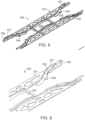
- FIGS. 8 and 9 show an embodiment of a frame 150 suitable for guiding the transfer conveyor belts 130, 140, as well as moving the lifting flaps 131, 141 between the deployed and retracted position.
- the illustrative frame 150 comprises props 151, 152 extending alone each side of the carryway.
- the props 151, 152 may be attached to the product conveyor frames (not shown).
- the illustrative props have a main body formed of sheet metal and including openings to reduce weight, but the invention is not so limited. A straight outer edge of the main body overlies the side edges of the product conveyors and spans the transfer gap between the product conveyors 10, 40.
- each prop 151, 152 forms a channel 154 for guiding a transfer conveyor belt 130 or 140.
- the channel comprises an inner side wall 156, an outer side wall 157 and a bottom wall 158.
- the inner side wall 156 holds the flaps 131, 141 in the retracted position and only extends along the first end sections of the props 151, 152.
- the channel 154 Downstream of the inner side wall 156, the channel 154 includes a twisting flap dropping guide 162 for dropping the lifting flaps to the deployed position as the modules pass through the channel 154.
- the outer side walls 157 extend from a straight first section adjacent the side edges of the first product conveyor at the first longitudinal location 15 to a curved second section. In the curved second section, the outer side walls curve laterally inward, pushing the conveyor belt modules 200 towards the center of the carryway. With the flaps in the deployed position, the transfer conveyor belts 130, 140 converge, placing the deployed flaps 131, 141 under the conveyed product with minimal impact on the product.
- the outer side walls 157 form a narrowed carryway that is just wide enough to fit the product, so that the lifting flaps 131, 141 effect the conveying of the product.
- the frame 150 includes a transfer plate 153 that bridges the product conveyors.
- the illustrative transfer plate is curved and arcs over the transfer gap 14 between conveyor ends.
- the outer side walls 157 also bridge the transfer gap 14.
- the illustrative outer side walls are also arc-shaped and continue adjacent to the sides of the curved transfer plate 153 to confine and guide the transfer conveyor belts 130, 140.
- the transfer conveyor belts 130, 140 lift and carry the conveyed product over the transfer gap 14.
- the transfer section of the transfer conveyor 30 is flat and the invention is not limited to arched components.
- the outer side walls 157 form another curved section, causing the outer side walls 157 to widen out again to the side edges of the second product conveyor 40, pulling the flaps from under the product and transferring the product 20 to the second product conveyor 40.
- a twisting flap-lifting guide 164 pushes the flap 131 or 141 back to a vertical, retracted position for travel in the returnway 169.
- Inner side walls each 158 form another belt-guiding channel with the last, straight section of the outer side walls 157 to guide the transfer conveyor belts to the reversing element 112. The belt-guiding channel pushes the belt modules back to the side edges of the product conveyor 40 and holds the flaps in the retracted position. The flaps remain in the retracted position in the returnway 169.
- the illustrative transfer conveyor provides gentle handling of products, reducing manual intervention during transfer.
- flap actuators comprise twisting guides
- alternative means for flipping the flaps between the deployed and retracted position may be used.
- a mechanical, electrical or magnetic means may be used to move the flaps between the deployed and retracted positions.
Landscapes
- Engineering & Computer Science (AREA)
- Mechanical Engineering (AREA)
- Intermediate Stations On Conveyors (AREA)
Claims (9)
- Transporteur de transfert (30) pour transférer un produit (20), comprenant :un cadre (150) configuré pour recouvrir un espace de transfert (14) entre un premier transporteur de produit (10) et un second transporteur de produit (40), le cadre (150) comprenantune première paroi latérale extérieure (157) ayant une première section qui s'étend le long d'un premier côté du premier transporteur de produit, une deuxième section qui s'incurve latéralement vers l'intérieur et une troisième section qui relie l'espace de transfert (14),une seconde paroi latérale extérieure (157) ayant une première section qui s'étend le long d'un second côté du premier transporteur de produit, une deuxième section qui s'incurve latéralement vers l'intérieur et une troisième section qui relie l'espace de transfert (14), etune plaque de transfert (153) s'étendant entre les troisièmes sections des première et deuxième parois latérales extérieures (157), la plaque de transfert (153) reliant l'espace de transfert (14) ; une première plaque de transfert (130) comprenant une pluralité de modules articulés (200) capables de se déplacer latéralement l'un par rapport à l'autre et de former une boucle sans fin, la première courroie transporteuse de transfert (130) s'étendant entre le premier transporteur de produit (10) et le second transporteur de produit (4) adjacent à la première paroi latérale externe (157) ; etune seconde courroie transporteuse de transfert (140) comprenant une pluralité de modules articulés (200) capables de se déplacer latéralement l'un par rapport à l'autre et de former une boucle sans fin, la seconde courroie transporteuse de transfert s'étendant entre le premier transporteur de produit (10) et le second transporteur de produit (40) adjacent à la seconde paroi latérale extérieure (157) ;dans lequel le cadre (150) comprend en outre une première paroi latérale intérieure (156) opposée à la première section de la première paroi latérale extérieures (157) pour former un canal (154) afin de guider la première courroie transporteuse de transfert (130).
- Transporteur de transfert (30) selon la revendication 1, dans lequel les première et seconde parois latérales extérieures (157) comprennent chacune une quatrième section qui s'incurve latéralement vers l'extérieur vers les bords latéraux du second transporteur de produit (40).
- Transporteur de transfert (30) selon la revendication 2, dans lequel les première et seconde parois latérales extérieures (157) comprennent chacune une cinquième section s'étendant le long de chaque bord latéral du second transporteur de produit (40).
- Transporteur de transfert (30) selon la revendication 1, dans lequel la première courroie transporteuse de transfert (130) comprend une pluralité de rabats mobiles (131) pour soulever et transporter le produit sur l'espace de transfert (14) .
- Transporteur de transfert (30) selon la revendication 4, dans lequel la première courroie transporteuse de transfert (130) comprend en outre un guide de levage de volet de torsion (162) pour déployer les volets mobiles (131) en amont de la première paroi latérale intérieure (156).
- Transporteur de transfert (30) selon la revendication 5, dans lequel le cadre (15) comprend en outre un guide de levage de volet de torsion (164) près de la quatrième section de la première paroi latérale extérieure (156) pour soulever les volets mobiles (131) dans une position inactive.
- Transporteur de transfert (30) selon la revendication 6, comprenant en outre une seconde paroi latérale intérieure (156) opposée à la cinquième section de la première paroi latérale extérieure (157) pour retenir les volets mobiles (131) dans la position inactive.
- Transporteur de transfert (30) selon la revendication 1, dans lequel la première plaque de transport (153) est incurvée verticalement pour former un arc sur l'espace de transfert (14).
- Système de transport (1), comprenant :un premier transporteur de produit (10) pour transporter un produit (20) d'une entrée à une sortie ; un second transporteur de produit (40) pour recevoir le produit (20) transporté par le premier transporteur de produit (10) et transporter le produit (20) à l'écart du premier transporteur de produit (10), le second transporteur de produit (40) ayant une entrée séparée de la sortie du premier transporteur de produit (10) par un espace de transfert (14) ; etle transporteur de transfert (30) selon l'une quelconque des revendications précédentes s'étendant entre le premier transporteur de produit (10) et le second transporteur de produit (40) pour soulever et transporter le produit sur l'espace de transfert (14).
Applications Claiming Priority (2)
| Application Number | Priority Date | Filing Date | Title |
|---|---|---|---|
| US202163137400P | 2021-01-14 | 2021-01-14 | |
| PCT/US2022/011792 WO2022155089A1 (fr) | 2021-01-14 | 2022-01-10 | Système de transport avec courroies de transfert |
Publications (2)
| Publication Number | Publication Date |
|---|---|
| EP4277866A1 EP4277866A1 (fr) | 2023-11-22 |
| EP4277866B1 true EP4277866B1 (fr) | 2024-12-11 |
Family
ID=80123429
Family Applications (1)
| Application Number | Title | Priority Date | Filing Date |
|---|---|---|---|
| EP22701804.1A Active EP4277866B1 (fr) | 2021-01-14 | 2022-01-10 | Système de transport avec courroies de transfert |
Country Status (3)
| Country | Link |
|---|---|
| US (1) | US12319515B2 (fr) |
| EP (1) | EP4277866B1 (fr) |
| WO (1) | WO2022155089A1 (fr) |
Family Cites Families (10)
| Publication number | Priority date | Publication date | Assignee | Title |
|---|---|---|---|---|
| JPS52117791A (en) * | 1976-03-27 | 1977-10-03 | Nobushige Sakai | Holding belt of hydraulic automatic peral oyster cleaner |
| JPS5479690U (fr) * | 1977-11-17 | 1979-06-06 | ||
| US4771877A (en) * | 1987-05-05 | 1988-09-20 | H. J. Langen & Sons Limited | Load spacing conveyor system |
| JPH0333817U (fr) * | 1989-08-09 | 1991-04-03 | ||
| US6260688B1 (en) * | 1999-01-22 | 2001-07-17 | Hartness International | Apparatus for controlling the flow of articles |
| US7055676B2 (en) * | 2003-11-13 | 2006-06-06 | Hartness International, Inc. | Conveyor with movable gripper and related conveyor link |
| US7278531B2 (en) * | 2004-06-29 | 2007-10-09 | Hartness International, Inc. | Flexible conveyor and connection elements |
| EP3160850A4 (fr) * | 2014-06-27 | 2018-01-24 | Graphic Packaging International, Inc. | Machine d'emballage à mouvement continu avec palettes rotatives |
| US9567164B2 (en) * | 2015-04-17 | 2017-02-14 | Laitram, L.L.C. | Conveyor system with transfer belts |
| US11708220B2 (en) * | 2021-10-21 | 2023-07-25 | Ems-Tech Inc. | High-capacity elevator conveying system |
-
2022
- 2022-01-10 US US18/266,104 patent/US12319515B2/en active Active
- 2022-01-10 EP EP22701804.1A patent/EP4277866B1/fr active Active
- 2022-01-10 WO PCT/US2022/011792 patent/WO2022155089A1/fr not_active Ceased
Also Published As
| Publication number | Publication date |
|---|---|
| WO2022155089A1 (fr) | 2022-07-21 |
| US20240034572A1 (en) | 2024-02-01 |
| EP4277866A1 (fr) | 2023-11-22 |
| US12319515B2 (en) | 2025-06-03 |
Similar Documents
| Publication | Publication Date | Title |
|---|---|---|
| US5667055A (en) | Device for aligning and spacing up groups of objects, such as cans, bottles and the like | |
| EP0664763B1 (fr) | Convoyeur-elevateur a godets | |
| CA1076948A (fr) | Machine d'emballage de bouteilles | |
| CN103596862B (zh) | 用于累积产品的装置 | |
| EP2195265B1 (fr) | Appareil de mesure de dispositif de transfert et procédés | |
| JP3256751B2 (ja) | 固形物の搬送装置 | |
| KR20080080520A (ko) | 통합형 롤러를 구비하는 컨베이어 플레이트 | |
| EP3820793B1 (fr) | Dispositif de déviation de plate-forme de bande transporteuse | |
| EP1193203B1 (fr) | Dispositif pour insérer des produits plats | |
| EP0665810B1 (fr) | Dispositif de relevement a mouvement continu | |
| EP4277866B1 (fr) | Système de transport avec courroies de transfert | |
| JPH0312003B2 (fr) | ||
| US4903823A (en) | Spatial conveyor for transferring newspapers, books and magazines | |
| RU99112478A (ru) | Способ и устройство для транспортировки отдельно взятых изделий | |
| CA2380139A1 (fr) | Courroie de transport radial avec structure evitant le pincement des griffes | |
| EP0608103A1 (fr) | Système de transport à poussoirs pour cartons en machines d'emballage | |
| US3937342A (en) | Apparatus for opening and unloading cartons | |
| US6170638B1 (en) | Stream aligner | |
| US3690439A (en) | Accumulating conveyor | |
| JP5343481B2 (ja) | 包装装置 | |
| EP0304545B1 (fr) | Appareil pour transférer une plaque lithograpghique | |
| NL8402358A (nl) | Transportinrichting. | |
| CN217349353U (zh) | 一种糕点生产用输送装置 | |
| WO2024163597A1 (fr) | Barre de compression en retrait pour un transporteur | |
| KR100235072B1 (ko) | 샌드위치식 컨베이어 시스템 |
Legal Events
| Date | Code | Title | Description |
|---|---|---|---|
| STAA | Information on the status of an ep patent application or granted ep patent |
Free format text: STATUS: UNKNOWN |
|
| STAA | Information on the status of an ep patent application or granted ep patent |
Free format text: STATUS: THE INTERNATIONAL PUBLICATION HAS BEEN MADE |
|
| PUAI | Public reference made under article 153(3) epc to a published international application that has entered the european phase |
Free format text: ORIGINAL CODE: 0009012 |
|
| STAA | Information on the status of an ep patent application or granted ep patent |
Free format text: STATUS: REQUEST FOR EXAMINATION WAS MADE |
|
| 17P | Request for examination filed |
Effective date: 20230615 |
|
| AK | Designated contracting states |
Kind code of ref document: A1 Designated state(s): AL AT BE BG CH CY CZ DE DK EE ES FI FR GB GR HR HU IE IS IT LI LT LU LV MC MK MT NL NO PL PT RO RS SE SI SK SM TR |
|
| DAV | Request for validation of the european patent (deleted) | ||
| DAX | Request for extension of the european patent (deleted) | ||
| GRAP | Despatch of communication of intention to grant a patent |
Free format text: ORIGINAL CODE: EPIDOSNIGR1 |
|
| STAA | Information on the status of an ep patent application or granted ep patent |
Free format text: STATUS: GRANT OF PATENT IS INTENDED |
|
| INTG | Intention to grant announced |
Effective date: 20240711 |
|
| GRAS | Grant fee paid |
Free format text: ORIGINAL CODE: EPIDOSNIGR3 |
|
| GRAA | (expected) grant |
Free format text: ORIGINAL CODE: 0009210 |
|
| STAA | Information on the status of an ep patent application or granted ep patent |
Free format text: STATUS: THE PATENT HAS BEEN GRANTED |
|
| P01 | Opt-out of the competence of the unified patent court (upc) registered |
Free format text: CASE NUMBER: APP_59146/2024 Effective date: 20241030 |
|
| AK | Designated contracting states |
Kind code of ref document: B1 Designated state(s): AL AT BE BG CH CY CZ DE DK EE ES FI FR GB GR HR HU IE IS IT LI LT LU LV MC MK MT NL NO PL PT RO RS SE SI SK SM TR |
|
| REG | Reference to a national code |
Ref country code: GB Ref legal event code: FG4D |
|
| REG | Reference to a national code |
Ref country code: CH Ref legal event code: EP |
|
| REG | Reference to a national code |
Ref country code: IE Ref legal event code: FG4D |
|
| REG | Reference to a national code |
Ref country code: DE Ref legal event code: R096 Ref document number: 602022008611 Country of ref document: DE |
|
| REG | Reference to a national code |
Ref country code: LT Ref legal event code: MG9D |
|
| PG25 | Lapsed in a contracting state [announced via postgrant information from national office to epo] |
Ref country code: HR Free format text: LAPSE BECAUSE OF FAILURE TO SUBMIT A TRANSLATION OF THE DESCRIPTION OR TO PAY THE FEE WITHIN THE PRESCRIBED TIME-LIMIT Effective date: 20241211 |
|
| PG25 | Lapsed in a contracting state [announced via postgrant information from national office to epo] |
Ref country code: FI Free format text: LAPSE BECAUSE OF FAILURE TO SUBMIT A TRANSLATION OF THE DESCRIPTION OR TO PAY THE FEE WITHIN THE PRESCRIBED TIME-LIMIT Effective date: 20241211 |
|
| PG25 | Lapsed in a contracting state [announced via postgrant information from national office to epo] |
Ref country code: BG Free format text: LAPSE BECAUSE OF FAILURE TO SUBMIT A TRANSLATION OF THE DESCRIPTION OR TO PAY THE FEE WITHIN THE PRESCRIBED TIME-LIMIT Effective date: 20241211 |
|
| REG | Reference to a national code |
Ref country code: NL Ref legal event code: MP Effective date: 20241211 |
|
| PG25 | Lapsed in a contracting state [announced via postgrant information from national office to epo] |
Ref country code: ES Free format text: LAPSE BECAUSE OF FAILURE TO SUBMIT A TRANSLATION OF THE DESCRIPTION OR TO PAY THE FEE WITHIN THE PRESCRIBED TIME-LIMIT Effective date: 20241211 |
|
| PG25 | Lapsed in a contracting state [announced via postgrant information from national office to epo] |
Ref country code: NO Free format text: LAPSE BECAUSE OF FAILURE TO SUBMIT A TRANSLATION OF THE DESCRIPTION OR TO PAY THE FEE WITHIN THE PRESCRIBED TIME-LIMIT Effective date: 20250311 |
|
| PG25 | Lapsed in a contracting state [announced via postgrant information from national office to epo] |
Ref country code: LV Free format text: LAPSE BECAUSE OF FAILURE TO SUBMIT A TRANSLATION OF THE DESCRIPTION OR TO PAY THE FEE WITHIN THE PRESCRIBED TIME-LIMIT Effective date: 20241211 Ref country code: GR Free format text: LAPSE BECAUSE OF FAILURE TO SUBMIT A TRANSLATION OF THE DESCRIPTION OR TO PAY THE FEE WITHIN THE PRESCRIBED TIME-LIMIT Effective date: 20250312 |
|
| PG25 | Lapsed in a contracting state [announced via postgrant information from national office to epo] |
Ref country code: RS Free format text: LAPSE BECAUSE OF FAILURE TO SUBMIT A TRANSLATION OF THE DESCRIPTION OR TO PAY THE FEE WITHIN THE PRESCRIBED TIME-LIMIT Effective date: 20250311 |
|
| PG25 | Lapsed in a contracting state [announced via postgrant information from national office to epo] |
Ref country code: NL Free format text: LAPSE BECAUSE OF FAILURE TO SUBMIT A TRANSLATION OF THE DESCRIPTION OR TO PAY THE FEE WITHIN THE PRESCRIBED TIME-LIMIT Effective date: 20241211 |
|
| REG | Reference to a national code |
Ref country code: AT Ref legal event code: MK05 Ref document number: 1750250 Country of ref document: AT Kind code of ref document: T Effective date: 20241211 |
|
| PG25 | Lapsed in a contracting state [announced via postgrant information from national office to epo] |
Ref country code: SM Free format text: LAPSE BECAUSE OF FAILURE TO SUBMIT A TRANSLATION OF THE DESCRIPTION OR TO PAY THE FEE WITHIN THE PRESCRIBED TIME-LIMIT Effective date: 20241211 |
|
| PG25 | Lapsed in a contracting state [announced via postgrant information from national office to epo] |
Ref country code: PL Free format text: LAPSE BECAUSE OF FAILURE TO SUBMIT A TRANSLATION OF THE DESCRIPTION OR TO PAY THE FEE WITHIN THE PRESCRIBED TIME-LIMIT Effective date: 20241211 |
|
| PG25 | Lapsed in a contracting state [announced via postgrant information from national office to epo] |
Ref country code: IS Free format text: LAPSE BECAUSE OF FAILURE TO SUBMIT A TRANSLATION OF THE DESCRIPTION OR TO PAY THE FEE WITHIN THE PRESCRIBED TIME-LIMIT Effective date: 20250411 |
|
| PG25 | Lapsed in a contracting state [announced via postgrant information from national office to epo] |
Ref country code: PT Free format text: LAPSE BECAUSE OF FAILURE TO SUBMIT A TRANSLATION OF THE DESCRIPTION OR TO PAY THE FEE WITHIN THE PRESCRIBED TIME-LIMIT Effective date: 20250411 |
|
| PG25 | Lapsed in a contracting state [announced via postgrant information from national office to epo] |
Ref country code: EE Free format text: LAPSE BECAUSE OF FAILURE TO SUBMIT A TRANSLATION OF THE DESCRIPTION OR TO PAY THE FEE WITHIN THE PRESCRIBED TIME-LIMIT Effective date: 20241211 |
|
| PG25 | Lapsed in a contracting state [announced via postgrant information from national office to epo] |
Ref country code: AT Free format text: LAPSE BECAUSE OF FAILURE TO SUBMIT A TRANSLATION OF THE DESCRIPTION OR TO PAY THE FEE WITHIN THE PRESCRIBED TIME-LIMIT Effective date: 20241211 Ref country code: RO Free format text: LAPSE BECAUSE OF FAILURE TO SUBMIT A TRANSLATION OF THE DESCRIPTION OR TO PAY THE FEE WITHIN THE PRESCRIBED TIME-LIMIT Effective date: 20241211 |
|
| PG25 | Lapsed in a contracting state [announced via postgrant information from national office to epo] |
Ref country code: SK Free format text: LAPSE BECAUSE OF FAILURE TO SUBMIT A TRANSLATION OF THE DESCRIPTION OR TO PAY THE FEE WITHIN THE PRESCRIBED TIME-LIMIT Effective date: 20241211 |
|
| PG25 | Lapsed in a contracting state [announced via postgrant information from national office to epo] |
Ref country code: CZ Free format text: LAPSE BECAUSE OF FAILURE TO SUBMIT A TRANSLATION OF THE DESCRIPTION OR TO PAY THE FEE WITHIN THE PRESCRIBED TIME-LIMIT Effective date: 20241211 |
|
| REG | Reference to a national code |
Ref country code: CH Ref legal event code: PL |
|
| PG25 | Lapsed in a contracting state [announced via postgrant information from national office to epo] |
Ref country code: SE Free format text: LAPSE BECAUSE OF FAILURE TO SUBMIT A TRANSLATION OF THE DESCRIPTION OR TO PAY THE FEE WITHIN THE PRESCRIBED TIME-LIMIT Effective date: 20241211 |
|
| REG | Reference to a national code |
Ref country code: DE Ref legal event code: R097 Ref document number: 602022008611 Country of ref document: DE |
|
| PG25 | Lapsed in a contracting state [announced via postgrant information from national office to epo] |
Ref country code: MC Free format text: LAPSE BECAUSE OF FAILURE TO SUBMIT A TRANSLATION OF THE DESCRIPTION OR TO PAY THE FEE WITHIN THE PRESCRIBED TIME-LIMIT Effective date: 20241211 Ref country code: LU Free format text: LAPSE BECAUSE OF NON-PAYMENT OF DUE FEES Effective date: 20250110 |
|
| PG25 | Lapsed in a contracting state [announced via postgrant information from national office to epo] |
Ref country code: DK Free format text: LAPSE BECAUSE OF FAILURE TO SUBMIT A TRANSLATION OF THE DESCRIPTION OR TO PAY THE FEE WITHIN THE PRESCRIBED TIME-LIMIT Effective date: 20241211 |
|
| PG25 | Lapsed in a contracting state [announced via postgrant information from national office to epo] |
Ref country code: BE Free format text: LAPSE BECAUSE OF NON-PAYMENT OF DUE FEES Effective date: 20250131 |
|
| PLBE | No opposition filed within time limit |
Free format text: ORIGINAL CODE: 0009261 |
|
| STAA | Information on the status of an ep patent application or granted ep patent |
Free format text: STATUS: NO OPPOSITION FILED WITHIN TIME LIMIT |
|
| PG25 | Lapsed in a contracting state [announced via postgrant information from national office to epo] |
Ref country code: CH Free format text: LAPSE BECAUSE OF NON-PAYMENT OF DUE FEES Effective date: 20250131 |
|
| REG | Reference to a national code |
Ref country code: BE Ref legal event code: MM Effective date: 20250131 |
|
| 26N | No opposition filed |
Effective date: 20250912 |
|
| PGFP | Annual fee paid to national office [announced via postgrant information from national office to epo] |
Ref country code: GB Payment date: 20251211 Year of fee payment: 5 |
|
| PGFP | Annual fee paid to national office [announced via postgrant information from national office to epo] |
Ref country code: FR Payment date: 20251216 Year of fee payment: 5 |
|
| PG25 | Lapsed in a contracting state [announced via postgrant information from national office to epo] |
Ref country code: IE Free format text: LAPSE BECAUSE OF NON-PAYMENT OF DUE FEES Effective date: 20250110 |
|
| PGFP | Annual fee paid to national office [announced via postgrant information from national office to epo] |
Ref country code: DE Payment date: 20251222 Year of fee payment: 5 |
|
| PGFP | Annual fee paid to national office [announced via postgrant information from national office to epo] |
Ref country code: IT Payment date: 20260112 Year of fee payment: 5 |