EP4278428B1 - Machine dynamoélectrique à refroidissement du système de bague collectrice - Google Patents
Machine dynamoélectrique à refroidissement du système de bague collectrice Download PDFInfo
- Publication number
- EP4278428B1 EP4278428B1 EP22701308.3A EP22701308A EP4278428B1 EP 4278428 B1 EP4278428 B1 EP 4278428B1 EP 22701308 A EP22701308 A EP 22701308A EP 4278428 B1 EP4278428 B1 EP 4278428B1
- Authority
- EP
- European Patent Office
- Prior art keywords
- slip ring
- shaft
- axially
- ring body
- cavity
- Prior art date
- Legal status (The legal status is an assumption and is not a legal conclusion. Google has not performed a legal analysis and makes no representation as to the accuracy of the status listed.)
- Active
Links
Images


Classifications
-
- H—ELECTRICITY
- H02—GENERATION; CONVERSION OR DISTRIBUTION OF ELECTRIC POWER
- H02K—DYNAMO-ELECTRIC MACHINES
- H02K13/00—Structural associations of current collectors with motors or generators, e.g. brush mounting plates or connections to windings; Disposition of current collectors in motors or generators; Arrangements for improving commutation
- H02K13/003—Structural associations of slip-rings
-
- H—ELECTRICITY
- H02—GENERATION; CONVERSION OR DISTRIBUTION OF ELECTRIC POWER
- H02K—DYNAMO-ELECTRIC MACHINES
- H02K17/00—Asynchronous induction motors; Asynchronous induction generators
- H02K17/02—Asynchronous induction motors
- H02K17/22—Asynchronous induction motors having rotors with windings connected to slip-rings
- H02K17/24—Asynchronous induction motors having rotors with windings connected to slip-rings in which both stator and rotor are fed with AC
-
- H—ELECTRICITY
- H02—GENERATION; CONVERSION OR DISTRIBUTION OF ELECTRIC POWER
- H02K—DYNAMO-ELECTRIC MACHINES
- H02K17/00—Asynchronous induction motors; Asynchronous induction generators
- H02K17/42—Asynchronous induction generators
-
- H—ELECTRICITY
- H02—GENERATION; CONVERSION OR DISTRIBUTION OF ELECTRIC POWER
- H02K—DYNAMO-ELECTRIC MACHINES
- H02K7/00—Arrangements for handling mechanical energy structurally associated with dynamo-electric machines, e.g. structural association with mechanical driving motors or auxiliary dynamo-electric machines
- H02K7/18—Structural association of electric generators with mechanical driving motors, e.g. with turbines
- H02K7/1807—Rotary generators
- H02K7/1823—Rotary generators structurally associated with turbines or similar engines
- H02K7/183—Rotary generators structurally associated with turbines or similar engines wherein the turbine is a wind turbine
-
- H—ELECTRICITY
- H02—GENERATION; CONVERSION OR DISTRIBUTION OF ELECTRIC POWER
- H02K—DYNAMO-ELECTRIC MACHINES
- H02K9/00—Arrangements for cooling or ventilating
- H02K9/02—Arrangements for cooling or ventilating by ambient air flowing through the machine
- H02K9/04—Arrangements for cooling or ventilating by ambient air flowing through the machine having means for generating a flow of cooling medium
-
- H—ELECTRICITY
- H02—GENERATION; CONVERSION OR DISTRIBUTION OF ELECTRIC POWER
- H02K—DYNAMO-ELECTRIC MACHINES
- H02K9/00—Arrangements for cooling or ventilating
- H02K9/28—Cooling of commutators, slip-rings or brushes e.g. by ventilating
-
- F—MECHANICAL ENGINEERING; LIGHTING; HEATING; WEAPONS; BLASTING
- F03—MACHINES OR ENGINES FOR LIQUIDS; WIND, SPRING, OR WEIGHT MOTORS; PRODUCING MECHANICAL POWER OR A REACTIVE PROPULSIVE THRUST, NOT OTHERWISE PROVIDED FOR
- F03D—WIND MOTORS
- F03D9/00—Adaptations of wind motors for special use; Combinations of wind motors with apparatus driven thereby; Wind motors specially adapted for installation in particular locations
- F03D9/20—Wind motors characterised by the driven apparatus
- F03D9/25—Wind motors characterised by the driven apparatus the apparatus being an electrical generator
-
- H—ELECTRICITY
- H01—ELECTRIC ELEMENTS
- H01R—ELECTRICALLY-CONDUCTIVE CONNECTIONS; STRUCTURAL ASSOCIATIONS OF A PLURALITY OF MUTUALLY-INSULATED ELECTRICAL CONNECTING ELEMENTS; COUPLING DEVICES; CURRENT COLLECTORS
- H01R39/00—Rotary current collectors, distributors or interrupters
- H01R39/02—Details for dynamo electric machines
- H01R39/08—Slip-rings
-
- Y—GENERAL TAGGING OF NEW TECHNOLOGICAL DEVELOPMENTS; GENERAL TAGGING OF CROSS-SECTIONAL TECHNOLOGIES SPANNING OVER SEVERAL SECTIONS OF THE IPC; TECHNICAL SUBJECTS COVERED BY FORMER USPC CROSS-REFERENCE ART COLLECTIONS [XRACs] AND DIGESTS
- Y02—TECHNOLOGIES OR APPLICATIONS FOR MITIGATION OR ADAPTATION AGAINST CLIMATE CHANGE
- Y02E—REDUCTION OF GREENHOUSE GAS [GHG] EMISSIONS, RELATED TO ENERGY GENERATION, TRANSMISSION OR DISTRIBUTION
- Y02E10/00—Energy generation through renewable energy sources
- Y02E10/70—Wind energy
- Y02E10/72—Wind turbines with rotation axis in wind direction
Definitions
- the invention relates to a dynamoelectric machine, in particular a double-fed asynchronous machine with a slip ring system, as a generator of a wind turbine.
- a three-phase system is impressed into the rotor.
- a slip ring system is used to transmit the current.
- the electrical three-phase system is transferred to slip rings and thus to the rotating part of the machine - the rotor - via stationary brushes.
- the three-phase system is led from the slip rings to the rotor winding of the rotor via appropriate conductors.
- Such a slip ring system for a dynamoelectric machine is used in wind turbines, for example.
- the electrical machines or generators and their components are made ever more compact. This means that, while the size remains the same, the thermal load on the slip ring components is increasing, as the temperatures, particularly of slip rings, slip ring brushes and brush holders, increase significantly.
- slip ring The increasing temperatures in the slip ring system, which are caused by ever higher power, have so far been reduced by increasing the surface area (slip ring, brushes, housing) tries to compensate so that the temperatures are back in the permissible range.
- a fan in the slip ring housing ensures air circulation by directing air from the outside (inside the nacelle) through the entire slip ring system, thus providing the necessary cooling of the system.
- EP 3 322 047 A1 A slip ring unit is known in which insulating segments between slip rings have cooling features.
- a slip ring system with a hollow shaft is known, whereby the hollow shaft is filled with two power lines.
- four axially extending, circumferentially distributed air passages are provided in the hollow shaft.
- the invention is therefore based on the object of further improving a slip ring system of a dynamoelectric machine, in particular a double-fed asynchronous machine, especially a wind turbine, with regard to the cooling performance and at the same time striving for the most cost-effective production possible.
- ASM asynchronous machine
- the special feature of the invention is that the supply lines to the rotor winding system are guided in the hollow shaft section assigned to the slip ring system, that the second limiting element has axially extending recesses for the discharge of the cooling medium flow, that the limiting elements are connected in one piece to the inside of the slip ring body and/or the shaft by shrinking, and that the limiting elements have axially extending recesses on the entire circumference for the supply and discharge of the cooling medium flow.
- the hollow space formed by the slip ring system is therefore used for the first time to guide and cool the thermally highly stressed power supply lines to the rotor windings.
- the cooling performance is improved by cooling not only the brushes, but also the supply lines to the rotor winding system.
- the Supply lines are routed at least in the area of the slip ring system inside the shaft, which of course has to be hollow there.
- cooling medium preferably cooling air
- recesses are provided at the axial beginning and at the axial end of the cavity through which the cooling air is guided axially.
- the cooling air is guided axially directly to the outlet area from the slip ring system - i.e. to the intake area of a blower or fan.
- the direct axial blowing or suction increases the air throughput and improves the cooling performance.
- the inventors recognized that cooling the supply lines is particularly important - alongside or in addition to cooling the grinding brushes.
- an internally cooled slip ring body can now be created via the axially open cavity on both sides with axial inlet and outlet openings. Not only can the slip ring body be cooled radially from the inside, but the cavity also contributes to cooling the shaft and the supply lines in this area of the shaft. The cavity therefore forms a heat sink during operation of the slip ring system and thus of the dynamoelectric machine.
- the shaft is hollow at least in the axial region of the slip ring body in order to conduct the excitation power from the slip ring system into the rotor or runner via electrical conductors, the conductors running there can also be cooled by the coolable shaft section.
- the conductors are designed as flexible conductors, for example stranded conductors, or as rigid conductors, in the form of a rail system and are used to excite a winding system of the rotor or runner.
- the slip ring body Due to the inventive design of the slip ring body, the slip ring body and additionally the following Components can be cooled:
- the shaft in particular the axial shaft section, and in the case of a hollow shaft, the stranded conductors running in the shaft, in particular arranged therein.
- the slip ring body, the shaft and the conductors for the excitation power, which run in the shaft or the axial hollow shaft section can now be cooled in a targeted manner, ie the heat load of these components can be absorbed by a coolant, in particular a cooling air flow.
- the slip rings are ring-shaped, i.e. they are hollow inside and have a defined ring width. They are used to transfer electrical energy from a static supply system to a rotating part (rotor) of a double-fed asynchronous machine. The transfer usually takes place using (grinding) brushes made of carbon, which are guided along a surface of the slip rings and transfer electrical energy to the slip rings, which then make it available to the winding system of the rotor via electrical conductors.
- the individual slip rings of each electrical phase are surrounded in the axial direction by insulating segments that electrically insulate the slip ring bodies from each other.
- a grounding ring is also insulated from the adjacent slip ring.
- At the other axial end of the slip ring body there is a support ring that is connected to the individual slip rings and the insulating bodies using connecting means (e.g. bolts) to give the slip ring body the necessary mechanical stability.
- the slip ring body has three slip rings in a three-phase system to be transmitted, a grounding ring that is electrically connected to the support structure, and an insulating sleeve to insulate the slip rings from the grounding ring and/or from each other. Insulating sleeve is arranged on the respective section of the supporting structure.
- a different electrical phase of the three-phase system is usually routed through each slip ring.
- the earthing ring is connected to the earthing system of, for example, the dynamoelectric machine and/or an entire system.
- the cavity is designed as a circumferential recess, so that the slip ring body is connected to the shaft in a rotationally fixed manner at least on two circumferentially spaced-apart end sections or limiting elements, thus creating the cavity that represents a cooling section.
- end sections or limiting elements can be designed in particular as rings or webs. They are part of the support structure and/or the shaft. They are thus formed in one piece with one or the other part and form the cooling section by axially attaching the slip ring body to the shaft or hollow shaft.
- the end sections or limiting elements, in particular the rings or webs there are axially extending recesses that enable the cooling described above.
- These recesses are now provided on the circumference of the support structure and/or shaft in the area of the rotationally fixed connection, according to the invention a shrinkage. These recesses are provided both on the bearing side (i.e. the side facing the rotor) and on the connection side (i.e. the side facing away from the rotor).
- cooling is now achieved by sucking in cooling air through additional recesses on the grounding ring on the bearing side or by pushing it there by a blower/fan.
- This cooling air passes through the cooling section, i.e. through these recesses the end sections, into the cavity, and absorbs the heat load there.
- the heated air is transported to the outside via openings in a slip ring housing via a fan, for example on the connection side. There, this heated air is expelled or recooled.
- the cooling system mentioned above supplements an existing cooling circuit in which the brushes and slip ring surface are already cooled by radial fans.
- the internally cooled slip ring body thus provides an additional cooling circuit for the shaft, the conductors running in the shaft, and the slip ring body.
- This cooling circuit significantly reduces the temperatures of the stranded conductors or a rail system in the shaft and the slip ring body through the additional cooling circuit created. This means that higher performance can be achieved with the same components in the same installation space of the slip ring system, which is extremely cost-effective.
- This design allows cool ambient air - or recooled air in the case of a closed system - to be guided through the very hot area between the shaft and the slip ring body, i.e. the hollow space, and thus the conductors, particularly stranded conductors in the shaft or hollow shaft section, are also cooled.
- the heated air is removed through openings in the grounding ring and through recesses on the bearing and connection side on the entire circumference of the slip ring body in the end sections.
- the cooler air is guided through these openings and the recesses into the hollow space between the shaft and the slip ring body.
- the air flow to be generated is supported by a separate or existing fan in the slip ring housing.
- the air is thus directed directly to the heated areas of the slip ring body, the shaft and indirectly the stranded conductors
- the areas between the shaft, slip ring body and the strands remain within the permissible temperature range and overheating of the slip ring system is prevented.
- a slip ring body with this cooling concept can therefore be used for significantly higher performance than before.
- the cavity can be created radially within the slip ring body by having the shaft with a diameter reduction over a predetermined axial length and/or the slip ring body with an diameter expansion in the area of the desired cavity.
- the slip ring body is thus connected to the shaft in a rotationally fixed manner via at least two circumferentially spaced-apart limiting elements, such as rings or webs.
- the limiting elements i.e. the rings or webs, are part of the supporting structure of the slip ring body and/or the shaft. They are thus formed in one piece with one or the other part and form the cooling section by axially attaching the slip ring body to the shaft or hollow shaft.
- the limiting elements e.g. the rings or webs, there are axially extending recesses that enable the cooling described above.
- the cavity may have meandering or labyrinth-like structures that extend the residence time of a cooling air flow in the cavity and thus allow the cooling air flow to absorb a higher heat load there.
- the structures can be separate, insertable elements or can already be incorporated into the slip ring body and/or the shaft.
- the cooling of the slip ring body axially attached to the electrical machine also Temperatures of the electrical machine, such as the shaft and rotor, are significantly reduced.
- the resulting lower temperature of the slip ring system allows smaller sizes of the slip ring bodies or the slip ring system.
- the slip ring system can therefore be loaded with more brushes per phase, which would not be possible without this type of cooling. This means that higher performance levels can be achieved with the same volume of the slip ring system than before.
- slip rings for example with grooves in the running surfaces that allow radial airflow, as well as with axial holes in the slip ring that allow axial cooling air flow.
- the insulating segments between the slip rings can also have a fan-like design to create turbulence in the slip ring housing when the slip ring body rotates.
- the brush device can also be cooled by adding measures to the brush shafts to increase their surface area. Targeted air flows using external fans and/or guide devices also contribute to cooling within the slip ring housing.
- the cooling circuits can be designed as closed cooling circuits or open cooling circuits.
- a closed cooling circuit the cooling medium, e.g. air
- the cooling medium e.g. air
- an open cooling circuit the cooling medium, e.g. air, is used from the environment and released back into the environment in a heated state.
- FIG 1 shows a basic longitudinal section of a dynamoelectric machine 24 in a housing 29.
- a stator 25 is inserted into the housing 29, which has a winding system 26 in grooves (not shown in detail) of a laminated core of the stator 25. Winding heads are formed on the front sides of the stator 25 by the winding system 26. Spaced from the stator 25 by an air gap 43 is a rotatably mounted rotor 27 with a winding system 28, which also forms winding heads on the front sides of the rotor 27.
- the rotor 27 is supported on the housing 29 of the machine 24 via bearings 30 and bearing shields.
- a slip ring system 1 is located in the axial extension of the dynamoelectric machine 24, which is connected to the winding system 28 of the rotor 27 via supply lines 35.
- the supply lines 35 run in a hollow shaft section of the shaft 4.
- the slip ring system 1 has, as can be seen from the following figures, a slip ring body 2 and a brush unit 14, which are housed in a slip ring housing 17.
- the slip ring body 2 has slip rings 3 arranged axially one behind the other, each of which is axially spaced from an insulating segment 7.
- Contact bolts 8 emerge axially from this insulating ring 5, each of which is electrically contacted with the respective associated slip ring 3.
- the brush unit 14 is positioned in a slip ring housing 17 and has one or more brushes 15 per electrical phase, i.e. per slip ring 3, which are assigned to the respective slip ring 3 or the grounding ring 6.
- the brushes 15 are each arranged in a brush holder 22, which also provides corresponding electrical contact devices.
- the brushes 15 per slip ring 3 are arranged next to one another and/or one behind the other.
- FIG 2 shows a basic longitudinal section of a slip ring body 2, wherein the slip rings 3 are arranged axially one behind the other and spaced apart from each other by respective insulating segments 7.
- the slip rings 3 are arranged on an insulating sleeve 16, which is arranged on a support structure 41 or hub.
- This support structure 41 is at the same electrical potential as the grounding ring 6.
- Each of the slip rings 3 is provided with one or more contact bolts 8 electrically contacted, so that the electrical energy provided on the running surface 10 of the respective slip ring 3 can be fed to the contact bolt 8 in order to be guided from there via conductors, in particular stranded conductors, through the hollow shaft or hollow shaft section to the winding system 28 of the rotor 27.
- the slip ring body 2 has an axial section on its radially inner side facing the shaft 4, which is set back with respect to the end sections 12 that delimit it, i.e. has a larger inner radius. Openings 21 are present in these end sections 12, which act as ventilation holes or vent holes. As soon as the slip ring body 2 is on a shaft 4 or hollow shaft, this comparatively larger inner radius creates a cavity 11 between the two end sections 12 of the support structure 41, i.e. the axial delimiting elements of the cavity 11, which can be designed as rings or webs.
- FIG 3 shows a slip ring body 2 in a partial perspective view from one end, more precisely from the machine side or bearing side 39.
- the grounding ring 6 can be seen on the end of the slip ring body 2 and its spacing from a slip ring 3 by an insulating segment 7.
- the running surface 10 of a slip ring 3 can also be seen, on which there are grooves 9 that also allow radial ventilation of the slip ring 3.
- Openings 13 are provided on the grounding ring 6, which allow an inflow of air via the openings 21 of the end sections or limiting elements into the cavity 11 that arises between the shaft 4 and the slip ring body 2.
- FIG 4 shows in a perspective view the slip ring body 3 from its other end face, the connection side 40.
- Contact bolts 8 emerge axially from the insulation ring 5, whereby each electrical phase or each slip ring 3 in this case is assigned two contact bolts 8. are.
- a sequence of insulation segments 7 and slip rings 3 is connected axially to this. The axial sequence is terminated by the grounding ring 6.
- the running surfaces 10 of the individual slip rings 3 have grooves 9 which are radially continuous and thus allow further cooling of the slip ring 3 if necessary.
- these slip rings 3 have axial openings which also contribute to cooling the slip rings 3.
- the insulation segments 7 are designed like blades on their radially outer edge so that air turbulence occurs when the slip ring body 2 rotates.
- the slip ring body 2 has a central opening 31 into which a shaft 4, a shaft 4 with an axial hollow shaft section or a hollow shaft is inserted.
- This shaft 4 is connected to the slip ring body 2 in a rotationally fixed manner.
- the winding system 28 of the rotor 27 is now supplied with electricity via the contact bolts 8 and the electrical supply lines 35 connected to them via a hollow shaft section of the shaft 4 or the hollow shaft.
- FIG 5 shows a longitudinal section of a slip ring system 1 with a slip ring body 2 and a brush unit 14.
- the slip ring body 2 is positioned on the shaft 4 with a hollow shaft section or hollow shaft in a rotationally fixed manner.
- supply lines 35 in the form of stranded conductors are led through the hollow shaft or hollow shaft section of the shaft 4 to the winding system 28 of the rotor 27 (not shown in detail in this figure).
- These supply lines 35 are either freely located in the hollow shaft or are embedded in a type of thermal paste in order to obtain good thermal contact with the shaft 4.
- Cooling is achieved in particular by an air flow arranged by a fan unit 19 on the connection side 40.
- a fan 20 sucks or pushes a cooling air flow into the slip ring housing 17, which guides the cooling air flow and directs it to the heat sources of the slip ring system 1 by appropriately designing the guide and guiding devices.
- the fan 20 in the present case is particularly responsible for the cooling air 33 through the cavity 11. Air is sucked in from the environment, in the case of a wind generator from the nacelle, and released again via an air outlet 38 on the slip ring system 1.
- FIG 6 shows the course of the cooling air flows 33 in an arrangement according to Figure 5
- heat is introduced 34 into the cooling air 33 guided through the cavity 11 by the slip rings 3 as well as by the shaft 4 and thus also by the supply lines 35 (stranded conductor or rail system).
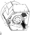
- FIG 7 shows a perspective view of the slip ring system 1 from the bearing side 39.
- the slip ring housing 17 is shown with its air inlets 18 and air outlets 38, which enable cooling of the slip ring system 1.
- the brush unit 14 is supported in the slip ring housing 17.
- the slip ring body 2 with its slip rings 3 is positioned radially further inside and on a shaft 4 or hollow shaft or hollow shaft section.
- the grounding ring 6 has openings 13 through which cooling air 33 can now be guided into or out of the cavity 11 via the holes 21 of the end sections 12.
- a fan unit 19 is connected axially to the slip ring housing 17, which controls the fan 20 and its distribution of the cooling air flows.
- the heated air is now preferably sucked in from the cavity 11 and discharged to the outside of the slip ring housing 17 through the fan cap 36.
- the contact bolts 8 are also cooled in the process.
- Such dynamoelectric machines 24 with a slip ring system 1 are designed in particular as double-fed asynchronous machines (ASM), which are used as generators in wind turbines, preferably in the power range between 0.5 and 8 MW.
- ASM asynchronous machines
- the wind turbines can be installed onshore or offshore.
Landscapes
- Engineering & Computer Science (AREA)
- Power Engineering (AREA)
- Life Sciences & Earth Sciences (AREA)
- Sustainable Development (AREA)
- Sustainable Energy (AREA)
- Motor Or Generator Cooling System (AREA)
- Motor Or Generator Current Collectors (AREA)
Claims (5)
- Machine dynamoélectrique (24), notamment machine asynchrone à double alimentation (ASM), comprenant- un stator (25) et un rotor (27) disposés solidairement en rotation sur un arbre (4) qui comprennent chacun un système d'enroulement (26, 28), le système d'enroulement (28) du rotor (27) pouvant être mis en contact électrique par le biais d'un système de bagues collectrices (1),- une unité de transmission d'énergie électrique du système de bagues collectrices (1), en particulier d'une unité à balais (14), un ou plusieurs balais (15) étant associés à une bague collectrice (3) par phase électrique, les balais (15) étant disposés sur un porte-balais (22),- un corps de bague collectrice (2) du système de bagues collectrices (1), qui comporte des bagues collectrices (3) disposées axialement les unes derrière les autres et associées à une phase électrique, qui sont espacées les unes des autres de manière isolée, le corps de bague collectrice (2) étant relié solidairement en rotation à l'arbre (4) et formant au moins par portions une cavité (11), ouverte axialement des deux côtés, entre le côté intérieur du corps de bague collectrice (2) et l'arbre (4), l'arbre (4) étant un arbre creux au moins dans la zone du système de bagues collectrices (1), des évidements (21) étant prévus axialement à l'intérieur de la cavité (11), à travers lesquels un flux de milieu de refroidissement peut être introduit axialement dans la cavité (11), la cavité (11) étant conçue comme un évidement circonférentiel de sorte que le corps de bague collectrice (2) soit en appui au moins sur deux éléments de limitation (12) qui sont espacés axialement, qui s'étendent circonférentiellement dont le premier comporte des évidements (21) s'étendant axialement destinés à introduire le flux de milieu de refroidissement, et le premier élément de limitation (12) comportant sur toute la circonférence les évidements (21) s'étendant axialement afin d'amener le flux de milieu de refroidissement, caractérisé en ce que, dans la portion d'arbre creux associée au système de bagues collectrices (1), les conduites d'alimentation (35) sont guidées vers le système d'enroulement (28) du rotor (27), en ce que le deuxième élément de limitation (12) comporte des évidements (21) qui s'étendent axialement et axialement à l'extérieur, qui sont destinés à évacuer le flux de milieu de refroidissement, à travers lesquels le flux de milieu de refroidissement peut être évacué axialement jusque dans une zone de sortie, en ce que les éléments de limitation (12) sont reliés par rétraction d'une seule pièce au côté intérieur du corps de bague collectrice (2) et/ou de l'arbre (4), et en ce que le deuxième élément de limitation (12) comporte sur toute la circonférence des évidements (21) qui s'étendent axialement et qui sont destinés à évacuer le flux de milieu de refroidissement.
- Machine dynamoélectrique (24), notamment machine asynchrone à double alimentation (ASM), selon la revendication 1, caractérisée en ce que, dans la zone de la cavité (11), l'arbre (4) présente une réduction de diamètre sur une longueur axiale spécifiée et/ou le corps de bague collectrice (3) présente une extension de diamètre.
- Machine dynamoélectrique (24), notamment machine asynchrone à double alimentation (ASM), selon la revendication 1 ou 2, caractérisée en ce que la cavité (11) comporte des moyens qui forment dans la cavité une structure en forme de labyrinthe et/ou de méandres. (11) afin d'augmenter le temps de séjour du flux de milieu de refroidissement, en particulier d'un flux d'air.
- Machine dynamoélectrique (24), notamment machine asynchrone à double alimentation (ASM), selon la revendication 3, caractérisé en ce que le flux d'air peut être généré par au moins un ventilateur propre ou externe.
- Éolienne comprenant une machine dynamoélectrique (24) selon l'une des revendications précédentes.
Applications Claiming Priority (2)
| Application Number | Priority Date | Filing Date | Title |
|---|---|---|---|
| EP21152087.9A EP4030595A1 (fr) | 2021-01-18 | 2021-01-18 | Machine dynamoélectrique à refroidissement du système de bague collectrice |
| PCT/EP2022/050419 WO2022152685A1 (fr) | 2021-01-18 | 2022-01-11 | Machine dynamo-électrique avec refroidissement du système à bagues collectrices |
Publications (2)
| Publication Number | Publication Date |
|---|---|
| EP4278428A1 EP4278428A1 (fr) | 2023-11-22 |
| EP4278428B1 true EP4278428B1 (fr) | 2024-09-04 |
Family
ID=74187155
Family Applications (2)
| Application Number | Title | Priority Date | Filing Date |
|---|---|---|---|
| EP21152087.9A Withdrawn EP4030595A1 (fr) | 2021-01-18 | 2021-01-18 | Machine dynamoélectrique à refroidissement du système de bague collectrice |
| EP22701308.3A Active EP4278428B1 (fr) | 2021-01-18 | 2022-01-11 | Machine dynamoélectrique à refroidissement du système de bague collectrice |
Family Applications Before (1)
| Application Number | Title | Priority Date | Filing Date |
|---|---|---|---|
| EP21152087.9A Withdrawn EP4030595A1 (fr) | 2021-01-18 | 2021-01-18 | Machine dynamoélectrique à refroidissement du système de bague collectrice |
Country Status (4)
| Country | Link |
|---|---|
| US (1) | US12244189B2 (fr) |
| EP (2) | EP4030595A1 (fr) |
| CN (1) | CN116783804A (fr) |
| WO (1) | WO2022152685A1 (fr) |
Families Citing this family (3)
| Publication number | Priority date | Publication date | Assignee | Title |
|---|---|---|---|---|
| EP4002647A1 (fr) * | 2020-11-12 | 2022-05-25 | Siemens Aktiengesellschaft | Machine electrique et centrale electrique eolienne |
| EP4030595A1 (fr) * | 2021-01-18 | 2022-07-20 | Flender GmbH | Machine dynamoélectrique à refroidissement du système de bague collectrice |
| CN115064914B (zh) * | 2022-07-22 | 2022-11-22 | 海外远景(北京)科技有限公司 | 一种盘式风力发电变桨滑环 |
Family Cites Families (18)
| Publication number | Priority date | Publication date | Assignee | Title |
|---|---|---|---|---|
| US1010522A (en) * | 1910-04-29 | 1911-12-05 | Gen Electric | Dynamo-electric machine. |
| DE504351C (de) * | 1927-05-29 | 1930-08-02 | Siemens Schuckertwerke Akt Ges | Anordnung zur Entfernung des Buerstenstaubes von den ungekapselten Schleifringen elektrischer Maschinen |
| DE918876C (de) * | 1942-03-07 | 1954-10-07 | Siemens Ag | Beluefteter Kollektor |
| US4137474A (en) * | 1974-06-04 | 1979-01-30 | Kraftwerk Union Aktiengesellschaft | Gas-cooled slip ring for electrical machines |
| US3997803A (en) * | 1974-08-01 | 1976-12-14 | Westinghouse Electric Corporation | Rotor member for dynamoelectric machines with longitudinal passages of decreasing area communicating with radial core vents |
| JPS56162953A (en) * | 1980-05-19 | 1981-12-15 | Hitachi Ltd | Current collector for rotary electric machine |
| JPS593768U (ja) * | 1982-06-29 | 1984-01-11 | 富士電機株式会社 | 回転電機のスリツプリング |
| JPS593768A (ja) | 1982-06-30 | 1984-01-10 | Fujitsu Ltd | テ−プ位置検出方式 |
| US5049771A (en) * | 1990-06-21 | 1991-09-17 | Iap Research, Inc. | Electrical machine |
| DE19807708A1 (de) * | 1998-02-24 | 1999-08-05 | Siemens Ag | Läufer und Verfahren zur Kühlung eines Schleifrings |
| ES2453866T3 (es) * | 2009-08-13 | 2014-04-08 | Alstom Renewable Technologies | Disposición de anillos colectores para una máquina eléctrica rotatoria |
| DE102012215018A1 (de) * | 2012-08-23 | 2014-02-27 | Robert Bosch Gmbh | Gehäuse für eine elektrische Maschine mit mäanderförmigem Kühlkanal und Leitgeometrien |
| JP5916223B2 (ja) * | 2012-12-05 | 2016-05-11 | トヨタ自動車株式会社 | スリップリング装置の冷却構造 |
| ES2863727T3 (es) * | 2013-12-20 | 2021-10-11 | Flender Gmbh | Dispositivo de contacto eléctrico para una máquina eléctrica |
| DE102013021745A1 (de) * | 2013-12-20 | 2015-06-25 | Sew-Eurodrive Gmbh & Co Kg | Umrichtermotor |
| EP3291423A1 (fr) | 2016-08-29 | 2018-03-07 | Siemens Aktiengesellschaft | Systeme de bague collectrice |
| EP3322047A1 (fr) | 2016-11-15 | 2018-05-16 | Siemens Aktiengesellschaft | Unité de bague collectrice comprenant un segment d'isolant de ventilateur |
| EP4030595A1 (fr) * | 2021-01-18 | 2022-07-20 | Flender GmbH | Machine dynamoélectrique à refroidissement du système de bague collectrice |
-
2021
- 2021-01-18 EP EP21152087.9A patent/EP4030595A1/fr not_active Withdrawn
-
2022
- 2022-01-11 WO PCT/EP2022/050419 patent/WO2022152685A1/fr not_active Ceased
- 2022-01-11 CN CN202280010552.3A patent/CN116783804A/zh active Pending
- 2022-01-11 EP EP22701308.3A patent/EP4278428B1/fr active Active
- 2022-01-11 US US18/272,751 patent/US12244189B2/en active Active
Also Published As
| Publication number | Publication date |
|---|---|
| EP4278428A1 (fr) | 2023-11-22 |
| US12244189B2 (en) | 2025-03-04 |
| WO2022152685A1 (fr) | 2022-07-21 |
| US20240162794A1 (en) | 2024-05-16 |
| EP4030595A1 (fr) | 2022-07-20 |
| CN116783804A (zh) | 2023-09-19 |
Similar Documents
| Publication | Publication Date | Title |
|---|---|---|
| EP4278428B1 (fr) | Machine dynamoélectrique à refroidissement du système de bague collectrice | |
| EP2580848B1 (fr) | Machine dynamoélectrique équipée d'un système de refroidissement d'air/de liquides | |
| DE102005044327B4 (de) | Elektrische Maschine mit Permanentmagneten | |
| DE102017202752B4 (de) | Rotor für eine elektrische Maschine | |
| DE102017201117A1 (de) | Verfahren zum Kühlen einer elektrischen Maschine sowie elektrische Maschine | |
| EP2406869B1 (fr) | Rotor pour un turbogénérateur et turbogénérateur doté d'un rotor | |
| DE10307813B4 (de) | Elektrische Maschine | |
| DE112015004112T5 (de) | Elektronikkühlturm einer sich axial erstreckenden elektrischen Maschine | |
| EP2930827B1 (fr) | Machine électrique à refroidissement par convection | |
| DE112011101406T5 (de) | Wechselstromgenerator mit doppeltem axialem Luftstrom | |
| EP3476012B1 (fr) | Unité de bague collectrice comprenant un segment d'isolant de ventilateur | |
| DE112015004606T5 (de) | Sockelfläche für MOSFET Modul | |
| DE102005059244A1 (de) | Sich drehende elektrische Maschine | |
| DE112015004094T5 (de) | Radial anpassbare Phasenanschlussdrahtverbindung | |
| DE102013100166B4 (de) | Drehende elektrische Maschine | |
| EP3172128B1 (fr) | Entraînement de nacelle électrique | |
| EP0589187B1 (fr) | Machine électrique entièrement fermeé, refroidie en surface par liquide | |
| DE102010003686A1 (de) | Elektrische Maschine mit Wickelkopf | |
| EP2804291A1 (fr) | Carter pour un moteur électrique | |
| EP0585644A1 (fr) | Machine électrique entièrement fermée, refroidie en surface par liquide | |
| EP2994979A2 (fr) | Système d'entraînement | |
| DE102021133860A1 (de) | Strömungselement und Elektrische Maschine mit Strömungselement | |
| WO2022042949A1 (fr) | Machine rotative électrodynamique auto-ventilée | |
| DE1903733A1 (de) | Vorrichtung zur Kommutator-und Buerstenkuehlung | |
| EP2847850B1 (fr) | Bobine pour une machine électrique |
Legal Events
| Date | Code | Title | Description |
|---|---|---|---|
| STAA | Information on the status of an ep patent application or granted ep patent |
Free format text: STATUS: UNKNOWN |
|
| STAA | Information on the status of an ep patent application or granted ep patent |
Free format text: STATUS: THE INTERNATIONAL PUBLICATION HAS BEEN MADE |
|
| PUAI | Public reference made under article 153(3) epc to a published international application that has entered the european phase |
Free format text: ORIGINAL CODE: 0009012 |
|
| STAA | Information on the status of an ep patent application or granted ep patent |
Free format text: STATUS: REQUEST FOR EXAMINATION WAS MADE |
|
| 17P | Request for examination filed |
Effective date: 20230801 |
|
| AK | Designated contracting states |
Kind code of ref document: A1 Designated state(s): AL AT BE BG CH CY CZ DE DK EE ES FI FR GB GR HR HU IE IS IT LI LT LU LV MC MK MT NL NO PL PT RO RS SE SI SK SM TR |
|
| DAV | Request for validation of the european patent (deleted) | ||
| DAX | Request for extension of the european patent (deleted) | ||
| GRAP | Despatch of communication of intention to grant a patent |
Free format text: ORIGINAL CODE: EPIDOSNIGR1 |
|
| STAA | Information on the status of an ep patent application or granted ep patent |
Free format text: STATUS: GRANT OF PATENT IS INTENDED |
|
| INTG | Intention to grant announced |
Effective date: 20240627 |
|
| GRAS | Grant fee paid |
Free format text: ORIGINAL CODE: EPIDOSNIGR3 |
|
| GRAA | (expected) grant |
Free format text: ORIGINAL CODE: 0009210 |
|
| STAA | Information on the status of an ep patent application or granted ep patent |
Free format text: STATUS: THE PATENT HAS BEEN GRANTED |
|
| AK | Designated contracting states |
Kind code of ref document: B1 Designated state(s): AL AT BE BG CH CY CZ DE DK EE ES FI FR GB GR HR HU IE IS IT LI LT LU LV MC MK MT NL NO PL PT RO RS SE SI SK SM TR |
|
| REG | Reference to a national code |
Ref country code: GB Ref legal event code: FG4D Free format text: NOT ENGLISH |
|
| REG | Reference to a national code |
Ref country code: CH Ref legal event code: EP |
|
| REG | Reference to a national code |
Ref country code: IE Ref legal event code: FG4D Free format text: LANGUAGE OF EP DOCUMENT: GERMAN |
|
| REG | Reference to a national code |
Ref country code: DE Ref legal event code: R096 Ref document number: 502022001620 Country of ref document: DE |
|
| REG | Reference to a national code |
Ref country code: LT Ref legal event code: MG9D |
|
| REG | Reference to a national code |
Ref country code: NL Ref legal event code: MP Effective date: 20240904 |
|
| PG25 | Lapsed in a contracting state [announced via postgrant information from national office to epo] |
Ref country code: NO Free format text: LAPSE BECAUSE OF FAILURE TO SUBMIT A TRANSLATION OF THE DESCRIPTION OR TO PAY THE FEE WITHIN THE PRESCRIBED TIME-LIMIT Effective date: 20241204 |
|
| PG25 | Lapsed in a contracting state [announced via postgrant information from national office to epo] |
Ref country code: GR Free format text: LAPSE BECAUSE OF FAILURE TO SUBMIT A TRANSLATION OF THE DESCRIPTION OR TO PAY THE FEE WITHIN THE PRESCRIBED TIME-LIMIT Effective date: 20241205 Ref country code: FI Free format text: LAPSE BECAUSE OF FAILURE TO SUBMIT A TRANSLATION OF THE DESCRIPTION OR TO PAY THE FEE WITHIN THE PRESCRIBED TIME-LIMIT Effective date: 20240904 |
|
| PG25 | Lapsed in a contracting state [announced via postgrant information from national office to epo] |
Ref country code: BG Free format text: LAPSE BECAUSE OF FAILURE TO SUBMIT A TRANSLATION OF THE DESCRIPTION OR TO PAY THE FEE WITHIN THE PRESCRIBED TIME-LIMIT Effective date: 20240904 |
|
| PG25 | Lapsed in a contracting state [announced via postgrant information from national office to epo] |
Ref country code: LV Free format text: LAPSE BECAUSE OF FAILURE TO SUBMIT A TRANSLATION OF THE DESCRIPTION OR TO PAY THE FEE WITHIN THE PRESCRIBED TIME-LIMIT Effective date: 20240904 |
|
| PG25 | Lapsed in a contracting state [announced via postgrant information from national office to epo] |
Ref country code: HR Free format text: LAPSE BECAUSE OF FAILURE TO SUBMIT A TRANSLATION OF THE DESCRIPTION OR TO PAY THE FEE WITHIN THE PRESCRIBED TIME-LIMIT Effective date: 20240904 |
|
| PG25 | Lapsed in a contracting state [announced via postgrant information from national office to epo] |
Ref country code: RS Free format text: LAPSE BECAUSE OF FAILURE TO SUBMIT A TRANSLATION OF THE DESCRIPTION OR TO PAY THE FEE WITHIN THE PRESCRIBED TIME-LIMIT Effective date: 20241204 Ref country code: ES Free format text: LAPSE BECAUSE OF FAILURE TO SUBMIT A TRANSLATION OF THE DESCRIPTION OR TO PAY THE FEE WITHIN THE PRESCRIBED TIME-LIMIT Effective date: 20240904 |
|
| PG25 | Lapsed in a contracting state [announced via postgrant information from national office to epo] |
Ref country code: RS Free format text: LAPSE BECAUSE OF FAILURE TO SUBMIT A TRANSLATION OF THE DESCRIPTION OR TO PAY THE FEE WITHIN THE PRESCRIBED TIME-LIMIT Effective date: 20241204 Ref country code: NO Free format text: LAPSE BECAUSE OF FAILURE TO SUBMIT A TRANSLATION OF THE DESCRIPTION OR TO PAY THE FEE WITHIN THE PRESCRIBED TIME-LIMIT Effective date: 20241204 Ref country code: LV Free format text: LAPSE BECAUSE OF FAILURE TO SUBMIT A TRANSLATION OF THE DESCRIPTION OR TO PAY THE FEE WITHIN THE PRESCRIBED TIME-LIMIT Effective date: 20240904 Ref country code: HR Free format text: LAPSE BECAUSE OF FAILURE TO SUBMIT A TRANSLATION OF THE DESCRIPTION OR TO PAY THE FEE WITHIN THE PRESCRIBED TIME-LIMIT Effective date: 20240904 Ref country code: GR Free format text: LAPSE BECAUSE OF FAILURE TO SUBMIT A TRANSLATION OF THE DESCRIPTION OR TO PAY THE FEE WITHIN THE PRESCRIBED TIME-LIMIT Effective date: 20241205 Ref country code: FI Free format text: LAPSE BECAUSE OF FAILURE TO SUBMIT A TRANSLATION OF THE DESCRIPTION OR TO PAY THE FEE WITHIN THE PRESCRIBED TIME-LIMIT Effective date: 20240904 Ref country code: ES Free format text: LAPSE BECAUSE OF FAILURE TO SUBMIT A TRANSLATION OF THE DESCRIPTION OR TO PAY THE FEE WITHIN THE PRESCRIBED TIME-LIMIT Effective date: 20240904 Ref country code: BG Free format text: LAPSE BECAUSE OF FAILURE TO SUBMIT A TRANSLATION OF THE DESCRIPTION OR TO PAY THE FEE WITHIN THE PRESCRIBED TIME-LIMIT Effective date: 20240904 |
|
| PG25 | Lapsed in a contracting state [announced via postgrant information from national office to epo] |
Ref country code: NL Free format text: LAPSE BECAUSE OF FAILURE TO SUBMIT A TRANSLATION OF THE DESCRIPTION OR TO PAY THE FEE WITHIN THE PRESCRIBED TIME-LIMIT Effective date: 20240904 |
|
| PG25 | Lapsed in a contracting state [announced via postgrant information from national office to epo] |
Ref country code: IS Free format text: LAPSE BECAUSE OF FAILURE TO SUBMIT A TRANSLATION OF THE DESCRIPTION OR TO PAY THE FEE WITHIN THE PRESCRIBED TIME-LIMIT Effective date: 20250104 Ref country code: PT Free format text: LAPSE BECAUSE OF FAILURE TO SUBMIT A TRANSLATION OF THE DESCRIPTION OR TO PAY THE FEE WITHIN THE PRESCRIBED TIME-LIMIT Effective date: 20250106 |
|
| PG25 | Lapsed in a contracting state [announced via postgrant information from national office to epo] |
Ref country code: RO Free format text: LAPSE BECAUSE OF FAILURE TO SUBMIT A TRANSLATION OF THE DESCRIPTION OR TO PAY THE FEE WITHIN THE PRESCRIBED TIME-LIMIT Effective date: 20240904 Ref country code: SM Free format text: LAPSE BECAUSE OF FAILURE TO SUBMIT A TRANSLATION OF THE DESCRIPTION OR TO PAY THE FEE WITHIN THE PRESCRIBED TIME-LIMIT Effective date: 20240904 |
|
| PG25 | Lapsed in a contracting state [announced via postgrant information from national office to epo] |
Ref country code: EE Free format text: LAPSE BECAUSE OF FAILURE TO SUBMIT A TRANSLATION OF THE DESCRIPTION OR TO PAY THE FEE WITHIN THE PRESCRIBED TIME-LIMIT Effective date: 20240904 |
|
| PG25 | Lapsed in a contracting state [announced via postgrant information from national office to epo] |
Ref country code: PL Free format text: LAPSE BECAUSE OF FAILURE TO SUBMIT A TRANSLATION OF THE DESCRIPTION OR TO PAY THE FEE WITHIN THE PRESCRIBED TIME-LIMIT Effective date: 20240904 Ref country code: CZ Free format text: LAPSE BECAUSE OF FAILURE TO SUBMIT A TRANSLATION OF THE DESCRIPTION OR TO PAY THE FEE WITHIN THE PRESCRIBED TIME-LIMIT Effective date: 20240904 |
|
| PG25 | Lapsed in a contracting state [announced via postgrant information from national office to epo] |
Ref country code: SK Free format text: LAPSE BECAUSE OF FAILURE TO SUBMIT A TRANSLATION OF THE DESCRIPTION OR TO PAY THE FEE WITHIN THE PRESCRIBED TIME-LIMIT Effective date: 20240904 Ref country code: IT Free format text: LAPSE BECAUSE OF FAILURE TO SUBMIT A TRANSLATION OF THE DESCRIPTION OR TO PAY THE FEE WITHIN THE PRESCRIBED TIME-LIMIT Effective date: 20240904 |
|
| REG | Reference to a national code |
Ref country code: DE Ref legal event code: R097 Ref document number: 502022001620 Country of ref document: DE |
|
| PG25 | Lapsed in a contracting state [announced via postgrant information from national office to epo] |
Ref country code: DK Free format text: LAPSE BECAUSE OF FAILURE TO SUBMIT A TRANSLATION OF THE DESCRIPTION OR TO PAY THE FEE WITHIN THE PRESCRIBED TIME-LIMIT Effective date: 20240904 |
|
| PLBE | No opposition filed within time limit |
Free format text: ORIGINAL CODE: 0009261 |
|
| STAA | Information on the status of an ep patent application or granted ep patent |
Free format text: STATUS: NO OPPOSITION FILED WITHIN TIME LIMIT |
|
| 26N | No opposition filed |
Effective date: 20250605 |
|
| REG | Reference to a national code |
Ref country code: CH Ref legal event code: PL |
|
| PG25 | Lapsed in a contracting state [announced via postgrant information from national office to epo] |
Ref country code: SE Free format text: LAPSE BECAUSE OF FAILURE TO SUBMIT A TRANSLATION OF THE DESCRIPTION OR TO PAY THE FEE WITHIN THE PRESCRIBED TIME-LIMIT Effective date: 20240904 |
|
| PG25 | Lapsed in a contracting state [announced via postgrant information from national office to epo] |
Ref country code: LU Free format text: LAPSE BECAUSE OF NON-PAYMENT OF DUE FEES Effective date: 20250111 Ref country code: MC Free format text: LAPSE BECAUSE OF FAILURE TO SUBMIT A TRANSLATION OF THE DESCRIPTION OR TO PAY THE FEE WITHIN THE PRESCRIBED TIME-LIMIT Effective date: 20240904 |
|
| PG25 | Lapsed in a contracting state [announced via postgrant information from national office to epo] |
Ref country code: BE Free format text: LAPSE BECAUSE OF NON-PAYMENT OF DUE FEES Effective date: 20250131 |
|
| PG25 | Lapsed in a contracting state [announced via postgrant information from national office to epo] |
Ref country code: FR Free format text: LAPSE BECAUSE OF NON-PAYMENT OF DUE FEES Effective date: 20250131 |
|
| PG25 | Lapsed in a contracting state [announced via postgrant information from national office to epo] |
Ref country code: CH Free format text: LAPSE BECAUSE OF NON-PAYMENT OF DUE FEES Effective date: 20250131 |
|
| REG | Reference to a national code |
Ref country code: BE Ref legal event code: MM Effective date: 20250131 |
|
| PG25 | Lapsed in a contracting state [announced via postgrant information from national office to epo] |
Ref country code: IE Free format text: LAPSE BECAUSE OF NON-PAYMENT OF DUE FEES Effective date: 20250111 |
|
| PGFP | Annual fee paid to national office [announced via postgrant information from national office to epo] |
Ref country code: DE Payment date: 20260128 Year of fee payment: 5 |
|
| PGFP | Annual fee paid to national office [announced via postgrant information from national office to epo] |
Ref country code: AT Payment date: 20260301 Year of fee payment: 5 |