EP4279027B1 - Biologische abdeckung - Google Patents
Biologische abdeckung Download PDFInfo
- Publication number
- EP4279027B1 EP4279027B1 EP23166990.4A EP23166990A EP4279027B1 EP 4279027 B1 EP4279027 B1 EP 4279027B1 EP 23166990 A EP23166990 A EP 23166990A EP 4279027 B1 EP4279027 B1 EP 4279027B1
- Authority
- EP
- European Patent Office
- Prior art keywords
- biological
- stent
- biological material
- cover
- opening
- Prior art date
- Legal status (The legal status is an assumption and is not a legal conclusion. Google has not performed a legal analysis and makes no representation as to the accuracy of the status listed.)
- Active
Links
Images



Classifications
-
- A—HUMAN NECESSITIES
- A61—MEDICAL OR VETERINARY SCIENCE; HYGIENE
- A61F—FILTERS IMPLANTABLE INTO BLOOD VESSELS; PROSTHESES; DEVICES PROVIDING PATENCY TO, OR PREVENTING COLLAPSING OF, TUBULAR STRUCTURES OF THE BODY, e.g. STENTS; ORTHOPAEDIC, NURSING OR CONTRACEPTIVE DEVICES; FOMENTATION; TREATMENT OR PROTECTION OF EYES OR EARS; BANDAGES, DRESSINGS OR ABSORBENT PADS; FIRST-AID KITS
- A61F2/00—Filters implantable into blood vessels; Prostheses, i.e. artificial substitutes or replacements for parts of the body; Appliances for connecting them with the body; Devices providing patency to, or preventing collapsing of, tubular structures of the body, e.g. stents
- A61F2/02—Prostheses implantable into the body
- A61F2/04—Hollow or tubular parts of organs, e.g. bladders, tracheae, bronchi or bile ducts
- A61F2/06—Blood vessels
- A61F2/07—Stent-grafts
-
- A—HUMAN NECESSITIES
- A61—MEDICAL OR VETERINARY SCIENCE; HYGIENE
- A61F—FILTERS IMPLANTABLE INTO BLOOD VESSELS; PROSTHESES; DEVICES PROVIDING PATENCY TO, OR PREVENTING COLLAPSING OF, TUBULAR STRUCTURES OF THE BODY, e.g. STENTS; ORTHOPAEDIC, NURSING OR CONTRACEPTIVE DEVICES; FOMENTATION; TREATMENT OR PROTECTION OF EYES OR EARS; BANDAGES, DRESSINGS OR ABSORBENT PADS; FIRST-AID KITS
- A61F2/00—Filters implantable into blood vessels; Prostheses, i.e. artificial substitutes or replacements for parts of the body; Appliances for connecting them with the body; Devices providing patency to, or preventing collapsing of, tubular structures of the body, e.g. stents
- A61F2/82—Devices providing patency to, or preventing collapsing of, tubular structures of the body, e.g. stents
-
- A—HUMAN NECESSITIES
- A61—MEDICAL OR VETERINARY SCIENCE; HYGIENE
- A61F—FILTERS IMPLANTABLE INTO BLOOD VESSELS; PROSTHESES; DEVICES PROVIDING PATENCY TO, OR PREVENTING COLLAPSING OF, TUBULAR STRUCTURES OF THE BODY, e.g. STENTS; ORTHOPAEDIC, NURSING OR CONTRACEPTIVE DEVICES; FOMENTATION; TREATMENT OR PROTECTION OF EYES OR EARS; BANDAGES, DRESSINGS OR ABSORBENT PADS; FIRST-AID KITS
- A61F2/00—Filters implantable into blood vessels; Prostheses, i.e. artificial substitutes or replacements for parts of the body; Appliances for connecting them with the body; Devices providing patency to, or preventing collapsing of, tubular structures of the body, e.g. stents
- A61F2/82—Devices providing patency to, or preventing collapsing of, tubular structures of the body, e.g. stents
- A61F2/92—Stents in the form of a rolled-up sheet expanding after insertion into the vessel, e.g. with a spiral shape in cross-section
-
- A—HUMAN NECESSITIES
- A61—MEDICAL OR VETERINARY SCIENCE; HYGIENE
- A61L—METHODS OR APPARATUS FOR STERILISING MATERIALS OR OBJECTS IN GENERAL; DISINFECTION, STERILISATION OR DEODORISATION OF AIR; CHEMICAL ASPECTS OF BANDAGES, DRESSINGS, ABSORBENT PADS OR SURGICAL ARTICLES; MATERIALS FOR BANDAGES, DRESSINGS, ABSORBENT PADS OR SURGICAL ARTICLES
- A61L31/00—Materials for other surgical articles, e.g. stents, stent-grafts, shunts, surgical drapes, guide wires, materials for adhesion prevention, occluding devices, surgical gloves, tissue fixation devices
- A61L31/005—Ingredients of undetermined constitution or reaction products thereof
-
- A—HUMAN NECESSITIES
- A61—MEDICAL OR VETERINARY SCIENCE; HYGIENE
- A61L—METHODS OR APPARATUS FOR STERILISING MATERIALS OR OBJECTS IN GENERAL; DISINFECTION, STERILISATION OR DEODORISATION OF AIR; CHEMICAL ASPECTS OF BANDAGES, DRESSINGS, ABSORBENT PADS OR SURGICAL ARTICLES; MATERIALS FOR BANDAGES, DRESSINGS, ABSORBENT PADS OR SURGICAL ARTICLES
- A61L31/00—Materials for other surgical articles, e.g. stents, stent-grafts, shunts, surgical drapes, guide wires, materials for adhesion prevention, occluding devices, surgical gloves, tissue fixation devices
- A61L31/04—Macromolecular materials
- A61L31/043—Proteins; Polypeptides; Degradation products thereof
- A61L31/044—Collagen
-
- A—HUMAN NECESSITIES
- A61—MEDICAL OR VETERINARY SCIENCE; HYGIENE
- A61L—METHODS OR APPARATUS FOR STERILISING MATERIALS OR OBJECTS IN GENERAL; DISINFECTION, STERILISATION OR DEODORISATION OF AIR; CHEMICAL ASPECTS OF BANDAGES, DRESSINGS, ABSORBENT PADS OR SURGICAL ARTICLES; MATERIALS FOR BANDAGES, DRESSINGS, ABSORBENT PADS OR SURGICAL ARTICLES
- A61L31/00—Materials for other surgical articles, e.g. stents, stent-grafts, shunts, surgical drapes, guide wires, materials for adhesion prevention, occluding devices, surgical gloves, tissue fixation devices
- A61L31/14—Materials characterised by their function or physical properties, e.g. injectable or lubricating compositions, shape-memory materials, surface modified materials
-
- A—HUMAN NECESSITIES
- A61—MEDICAL OR VETERINARY SCIENCE; HYGIENE
- A61L—METHODS OR APPARATUS FOR STERILISING MATERIALS OR OBJECTS IN GENERAL; DISINFECTION, STERILISATION OR DEODORISATION OF AIR; CHEMICAL ASPECTS OF BANDAGES, DRESSINGS, ABSORBENT PADS OR SURGICAL ARTICLES; MATERIALS FOR BANDAGES, DRESSINGS, ABSORBENT PADS OR SURGICAL ARTICLES
- A61L31/00—Materials for other surgical articles, e.g. stents, stent-grafts, shunts, surgical drapes, guide wires, materials for adhesion prevention, occluding devices, surgical gloves, tissue fixation devices
- A61L31/14—Materials characterised by their function or physical properties, e.g. injectable or lubricating compositions, shape-memory materials, surface modified materials
- A61L31/16—Biologically active materials, e.g. therapeutic substances
-
- A—HUMAN NECESSITIES
- A61—MEDICAL OR VETERINARY SCIENCE; HYGIENE
- A61F—FILTERS IMPLANTABLE INTO BLOOD VESSELS; PROSTHESES; DEVICES PROVIDING PATENCY TO, OR PREVENTING COLLAPSING OF, TUBULAR STRUCTURES OF THE BODY, e.g. STENTS; ORTHOPAEDIC, NURSING OR CONTRACEPTIVE DEVICES; FOMENTATION; TREATMENT OR PROTECTION OF EYES OR EARS; BANDAGES, DRESSINGS OR ABSORBENT PADS; FIRST-AID KITS
- A61F2/00—Filters implantable into blood vessels; Prostheses, i.e. artificial substitutes or replacements for parts of the body; Appliances for connecting them with the body; Devices providing patency to, or preventing collapsing of, tubular structures of the body, e.g. stents
- A61F2/02—Prostheses implantable into the body
- A61F2/04—Hollow or tubular parts of organs, e.g. bladders, tracheae, bronchi or bile ducts
- A61F2/06—Blood vessels
- A61F2/07—Stent-grafts
- A61F2002/075—Stent-grafts the stent being loosely attached to the graft material, e.g. by stitching
-
- A—HUMAN NECESSITIES
- A61—MEDICAL OR VETERINARY SCIENCE; HYGIENE
- A61F—FILTERS IMPLANTABLE INTO BLOOD VESSELS; PROSTHESES; DEVICES PROVIDING PATENCY TO, OR PREVENTING COLLAPSING OF, TUBULAR STRUCTURES OF THE BODY, e.g. STENTS; ORTHOPAEDIC, NURSING OR CONTRACEPTIVE DEVICES; FOMENTATION; TREATMENT OR PROTECTION OF EYES OR EARS; BANDAGES, DRESSINGS OR ABSORBENT PADS; FIRST-AID KITS
- A61F2210/00—Particular material properties of prostheses classified in groups A61F2/00 - A61F2/26 or A61F2/82 or A61F9/00 or A61F11/00 or subgroups thereof
- A61F2210/0076—Particular material properties of prostheses classified in groups A61F2/00 - A61F2/26 or A61F2/82 or A61F9/00 or A61F11/00 or subgroups thereof multilayered, e.g. laminated structures
-
- A—HUMAN NECESSITIES
- A61—MEDICAL OR VETERINARY SCIENCE; HYGIENE
- A61F—FILTERS IMPLANTABLE INTO BLOOD VESSELS; PROSTHESES; DEVICES PROVIDING PATENCY TO, OR PREVENTING COLLAPSING OF, TUBULAR STRUCTURES OF THE BODY, e.g. STENTS; ORTHOPAEDIC, NURSING OR CONTRACEPTIVE DEVICES; FOMENTATION; TREATMENT OR PROTECTION OF EYES OR EARS; BANDAGES, DRESSINGS OR ABSORBENT PADS; FIRST-AID KITS
- A61F2240/00—Manufacturing or designing of prostheses classified in groups A61F2/00 - A61F2/26 or A61F2/82 or A61F9/00 or A61F11/00 or subgroups thereof
- A61F2240/001—Designing or manufacturing processes
-
- A—HUMAN NECESSITIES
- A61—MEDICAL OR VETERINARY SCIENCE; HYGIENE
- A61L—METHODS OR APPARATUS FOR STERILISING MATERIALS OR OBJECTS IN GENERAL; DISINFECTION, STERILISATION OR DEODORISATION OF AIR; CHEMICAL ASPECTS OF BANDAGES, DRESSINGS, ABSORBENT PADS OR SURGICAL ARTICLES; MATERIALS FOR BANDAGES, DRESSINGS, ABSORBENT PADS OR SURGICAL ARTICLES
- A61L2430/00—Materials or treatment for tissue regeneration
- A61L2430/40—Preparation and treatment of biological tissue for implantation, e.g. decellularisation, cross-linking
Definitions
- the present application relates to a biological cover and a method for producing such a cover.
- An apparatus for manufacturing such a cover is described as well.
- vascular diseases In recent years, there has been an increase in vascular diseases. A steady advancement in medicine as well as medical technology has made it possible to treat a large number of these diseases with drugs and/or vascular interventions (e.g. cardiovascular interventions) in order to enable and/or support the patient's recovery and to adequately prevent the development of further secondary diseases.
- vascular interventions e.g. cardiovascular interventions
- stents are in many cases the means of choice, e.g. to eliminate (local) stenoses or to prevent their formation at an early stage.
- Such stents can be wire mesh-based, cylindrical devices that can be inserted into a patient's vein or artery during a vascular intervention and brought to a potential stenosis.
- Xenogeneic tissue in medicine refers to tissue that was isolated from a human or animal body of a different (heterologous) species.
- xenogeneic (also known as xenogenous or xenogenic) tissue is material that was isolated form a human or animal body which is different from the human or animal body where the implant is to be implanted.
- Xenogeneic tissue may also refer to tissue based on human or animal donor cells (cells obtained from a or the human or animal donor) being cultivated in a bioreactor or being obtained via 3D printing.
- the xenogeneic material e.g. tissue, can be in its native form, in a fixed form, in a processed form or can comprise combinations thereof.
- the mechanical fastening element may be attached to an outer surface of the stent.
- the mechanical fixation element may be in addition to a regular wire mesh of the stent.
- the mechanical fastening element may be integrally made with or attached (removably) to the stent.
- the mechanical fastening element may be provided as a mandrel-shaped fastening structure (which may extend orthogonally from the stent, for example). It may further be provided that the mandrel-shaped attachment structure may be transformed into a hook-shaped attachment structure by bending. Alternatively, the attachment structure may be provided prefabricated as a hook-shaped attachment structure.
- Providing the stent with a mechanical attachment structure provides an additional, mechanical means of attaching the biological coating to the stent, thereby providing additional adhesion of the biological coating to the stent (e.g. by pressing the first material (and thus preferably its collagen fibers) into the mechanical fastening element while pressing the first material against the counter element in the presence of the crosslinking agent) and to prevent an undesired displacement of the biological cover on the stent (e.g. along its longitudinal axis) or a detachment from the stent without having to resort to surgical suturing procedures.
- aspects of the present invention do not, however, preclude the use of surgical suturing techniques.
- the method may comprise providing a biological material and creating a tab element in the biological material. Further, the method may comprise creating an opening in the biological material for the tab element to pass through.
- the method may be combined with other process steps mentioned herein for the production of a biological coating for a stent.
- the tab element may have a relatively narrow section whose lateral dimension is adapted to the length of the opening. Its width may, for example, be adapted to (e.g., substantially correspond to) a thickness of the biological material. Thereafter, a section with a relatively larger lateral dimension may adjoin the outer side of the tab element. This section may, for example, prevent the tab element from slipping back out of the opening.
- the relatively narrow section can be obtained, for example, by appropriately cutting biological material from a pre-cut section that is, for example, rectangular.
- the relatively widened section may thereby be obtained, for example, by cutting less material from the rectangular precut, or may correspond, for example, to the corresponding original section of the rectangular precut.
- the biological material of the tab element may be (substantially) positively received by the opening, for example.
- the relatively narrow section of the tab element may, for example, form an at least partial positive fit with the opening.
- Providing the biological material with a tab element as well as with an opening may enable advantageous and quickly applicable mechanical attachment of the tab element in the opening, thereby enabling a contribution to a dimensionally stable biological cover for a stent.
- the opening and/or the tab element can be created such that the biological material can be converted into a (substantially) cylindrical shape by passing it through.
- the tab element and the opening may be created on two opposite sides, preferably along the longitudinal direction of the biological material, wherein the two opposite sides may be the sides that are brought together to form the (substantially) cylindrical arrangement.
- passing the tab element through the opening can provide mechanical stability, e.g., of the corresponding cylindrical configuration, even before the biological material is crosslinked. This can facilitate handling during preparation and execution of crosslinking.
- the tab element and opening can increase the mechanical stability of the configuration even after crosslinking and reduce the risk of detachment of e.g. the crosslinked sections of the tab element and the surrounding area of the opening (e.g. compared to an configuration in which only overlapping sections are crosslinked without passing a tab element through an opening).
- the crosslinked material can then be easily transferred to a cylindrical arrangement by passing the tab element through the opening.
- the opening and/or the tab element may be created such that the tab element and the opening may be movable relative to each other so that a diameter of the cylindrical shape may be varied.
- the opening and/or the tab element may be configured such that the diameter of the cylindrical shape may be (reversibly) increased upon dilatation of the stent. This can be achieved, for example, by making the relatively narrow portion of the tab element significantly longer than the thickness of the biological material. The tab element can then slide through the opening, for example, so that different diameters can be provided.
- the opening and/or the tab element in this way can allow the biological cover to be adapted to the current application.
- the crosslinking of the biological material can be done in such a way that the mobility between the opening and the tab element is provided even after crosslinking.
- this may allow the diameter to adapt to a state of dilatation of the stent while avoiding damage to the biological material (e.g., tearing).
- it may also allow the biological material to be adjusted to a specific diameter, for example, prior to crosslinking by means of the orifice and tab element, and then crosslinked at that diameter.
- the method may comprise the step of passing the tab element through the opening such that a (substantially) cylindrical configuration of the biological material is produced.
- a (substantially) cylindrical configuration may concentrically receive a stent therein.
- the biological cover By passing the tab element through the opening, a dimensionally stable, (substantially) cylindrical arrangement of the biological cover can be obtained.
- the biological cover can be kept dimensionally stable until it is used (e.g., attached to a stent) (e.g., as a "ready-to-use" system), which may allow independent fabrication of the stent and biological cover. This may promote simplified manufacture of the biological cover and may allow biological covers to be produced in stock and stored until their immediate use, which may help to ensure sufficient and rapidly usable biological covers.
- Crosslinking only after the biological material has been applied to the stent may allow for an immediate precise-fit application of the biological material to the stent, so that precise, precise-fit pre-dimensioning of the biological material (e.g., to the exact dimensions of the stent) may not be required, which may generally simplify the manufacturing process.
- the tab element may be configured such that it is movable relative to the opening along the feedthrough direction after passing through the opening.
- the tab element and the opening can be provided in such a way that a bidirectional movement of the tab element relative to the feed-through direction can be enabled.
- the tab element By allowing the tab element to move along a feedthrough direction, a variation of the diameter of the cover can be achieved, which can lead to both an increase and a decrease of the diameter of the cover. This can help to individualize the cover for different vascular interventions, and the biological material can also, for example, immediately follow an expansion of the stent to a required diameter.
- the biological material in a non-crosslinked state, it may be possible to pass the tab element through the opening until a desired diameter of the covering (in (substantially) a cylindrical configuration) is achieved. Subsequently, cross-linking of the biological material can be performed, thereby preventing further movement of the tab element relative to the opening and dilatation of the cover.
- a biological cover for a stent which may comprise a biological material that may comprise a main body and at least one attachment portion protruding away from the main body.
- the main body may be adapted to be transformed into a (substantially) cylindrical configuration.
- the biological cover may be produced by a method described herein.
- the at least one attachment portion protruding away from the main body may be configured to provide mechanical fixation of the biological material to the stent.
- the at least one attachment portion protruding away from the main body may further be configured to form a loop-like element for mechanical fixation, with which a mechanical connection between the at least one attachment portion protruding away from the main body and the stent may be established.
- the main body of the biological cover may be configured to be wound around an exterior of the stent (e.g., as a circumferential collar) and, by folding the at least one attachment portion protruding away from the main body into an opening of the stent, to be retained in the (substantially) cylindrical configuration.
- both the main body and/or the at least one fastening portion protruding away from the main body can be provided in non-crosslinked form and in crosslinked form.
- the advantageous effects as described herein can be obtained thereby.
- Such an embodiment of the biological cover may allow storage of the biological cover in a (substantially) two-dimensional form, wherein the biological cover can be converted to a (substantially) cylindrical configuration only upon use in clinical practice by attachment to a stent. This may contribute to simplified and space-saving storage of the biological material and allow modularization of biological covers relative to a stent.
- the device comprises a counter element and a pressure generating means.
- the pressure element is adapted to be introduced into an inner lumen of a (substantially) cylindrical biological material to press the biological material onto the counter element.
- the device is adapted to crosslink a biological cover for a stent, which may be provided in a (substantially) cylindrical configuration, in the presence of pressure and, if necessary, to crosslink regions of the biological material to be connected in the process.
- the counter element may be formed in one or two parts or may comprise more than two parts.
- the counter element may be provided as a (two-part) outer mold defining, for example, a cylindrical opening which may be adapted to receive the biological material and optionally a preferably cylindrical stent therein.
- the mating element may be adapted to (fully) receive the same.
- the counter element may be configured to be dimensionally stable so as to withstand dilatation, for example, by a balloon catheter.
- the apparatus may further comprise means for supplying and/or receiving a crosslinking agent.
- the pressure generating means may be provided, for example, as a dilatable tubing element (e.g., a balloon catheter).
- Such a device can provide a simplified and economical manufacturing process for a cover for a stent, by joining two (overlapping) regions of the biological cover, which can be achieved in the presence of a crosslinking agent and pressure on the site or elements of the biological material to be joined.
- the crosslinking may be performed directly on the stent and optionally the crosslinking may simultaneously provide an (additional) connection to the stent.
- the counter element may be provided to only partially surround the stent (e.g., in a cross-sectional view of the stent, only in a 180° angled portion).
- the counter element can be provided as a (polymeric) foam material that, when the biological material is pressed against the counter element, can apply a counter force.
- a rigid plate may be positioned below the foam material so that the rigid plate can act as a stabilizing foundation for the foam material.
- hygroscopic exchange materials include all biocompatible and non-volatile hygroscopic exchange materials, in particular hydrophilic hydrocarbons with a large number of hydroxyl groups, for example watersoluble sugar alcohols such as glycerol, or ethylene glycol or polyethylene glycol.
- the second variant of two or more hygroscopic exchange materials also includes embodiments in which the same exchange material is used, such as polyethylene glycol, but in different versions, such as with different molecular weights. All of the above substances are characterized by their hygroscopic properties, low toxicity values and excellent water solubility. The ability to absorb and bind moisture from the environment opens up a wide range of applications for glycerin and polyethylene glycol (PEG) in various suitable mixing ratios to bring about the stabilization of collagen-containing tissue.
- PEG polyethylene glycol
- Fig. 1A shows a cross-section of a stent 1, taken transversely to a longitudinal extension of the stent 1.
- Stent 1 may have an inner lumen Lu, which may be adapted to receive means to dilate the stent 1 in a radial direction and/or to be able to insert additional medical devices into the stent 1.
- Stent 1 preferably has a cylindrical shape or a circular cross-sectional shape.
- Stent 1 is further provided with a cover 3, preferably a biological cover 3, made of a first material 2 (e.g., a biological material such as a natively dried tissue (e.g., the use of natively dried pericardium may allow this cylindrical shape to already be formed from an originally flat, two-dimensional, native piece of tissue).
- a first material 2 e.g., a biological material such as a natively dried tissue (e.g., the use of natively dried pericardium may allow this cylindrical shape to already be formed from an originally flat, two-dimensional, native piece
- Cover 3 is preferably attached to the stent 1 in such a way that it completely surrounds the stent 1, e.g. in a 360° geometry. Cover 3 may thereby be provided as described herein and is provided in a (substantially) cylindrical configuration so as to encase the stent 1.
- Cover 3 comprises at least one overlapping region 4, which is configured as a fold, which may be obtained by folding at least a part of cover 3 along a longitudinal extension of stent 1, in itself. As a result of the folding, an overlapping region 4 is obtained, in which at least two layers of the first material may be superimposed.
- a second material 5 is introduced into the overlapping area 4, which is selected in such a way that, when a crosslinking agent is added, the first material 2 is not bonded in the areas where the second material 5 separates two overlapping areas of the first material 2 from one another, and the overlapping areas of the first material 2 in question thus remain movable relative to one another.
- the second material 5 can merely be introduced into the overlapping region 4 during the cross-linking of the first material 2 and removed again after the cross-linking process has been completed. Alternatively, however, it may also be possible to leave the second material 5 in the overlapping area 5 beyond the crosslinking.
- Fig. 1B shows the cover 3 of Fig. 1A in a cross-section (without the stent 1) in a partially unfolded state.
- at least part of the overlapping region created in the preparation step ( Fig. 1A ) may unfold, resulting in an at least partially unfolded region 6 of the cover 3.
- Fig. 1B further shows for better comprehensibility the second material 5, which (with reference to Fig. 1A ) is introduced into the at least partially unfolded area 6.
- the second material 5 can also, for example, completely enclose the first material 2 in order to improve the crosslinking process.
- Fig. 1C shows the stent 1 in a prefabricated state, i.e. in a state in which it has been encased with the cover 3 and the overlapping region 4 has been provided with the second material 5. Furthermore, a rigid element 7 can be introduced into the inner lumen Lu of the stent 1. In this state of fabrication of the stent 1 a cross-linking takes place.
- the cover 3 is subjected to only minimal mechanical stress, since as the diameter of the stent 1 increases, the cover 3 (and in particular the overlapping region 4) first unfolds before mechanical stress occurs in the plane of the first material 2.
- the length of the overlapping zone 4 may depend on the desired initial and final diameter of the cover 3. For the stent 1 considered above with an exemplary diameter of 6 French in a crimped condition, the length of the overlapping zone may be about 4.7 mm in order to completely avoid mechanical stress in the plane of the first material 2.
- the overlapping layers of the first material 2 resulting from folding can chemically bond (e.g., by crosslinking) in the overlapping region 5.
- about 0.1% to 50% or 0.5% to 40% or 1% to 30% of the overlapping region may be bonded.
- a possible example of this may be a series of punctate bonding sites (e.g., punctate free sites spaced 1 mm, 2 mm, 3 mm, 4 mm, 5 mm, 10 mm, etc.), along the longitudinal axis of the stent 1 in the anterior (i.e., a distal) region of the folded first material 2.
- the point chemical bonds formed during chemical cross-linking under pressure can keep the fold in the overlapping region 4 on the stent 1, so that unwanted unfolding during implantation is safely avoided. Only when the stent 1 is dilated, e.g., with a balloon, can the created junctions become loose. In this way, the cover 3 (and thus the first material 2) can dilate together with the stent 1 into a cylindrical shape.
- Figures 2A-2C show exemplary cut patterns for the cover 3 (and thus for the first material 2) according to one possible embodiment. It should be noted that aspects of this exemplary embodiment presented herein may also be combined with aspects of other embodiments.
- Fig. 2A shows a first exemplary cutting pattern (in an initially two-dimensional form) of a biological material for producing a cover 3 according to a possible embodiment.
- the cutting pattern may be provided with a (substantially) rectangular basic shape 8.
- the cutting pattern may further be produced from the biological material by means of a CO 2 laser, a pair of scissors, a scalpel, by punching, etc.
- At least two slits 9 are introduced into the (essentially) rectangular basic shape 8, which are introduced into the biological material on opposite sides of the rectangular basic shape 8, with respect to a longitudinal extension L of the rectangular basic shape 8.
- at least one tab element 10 can be formed in the rectangular basic shape 8.
- the width of the slits can be adapted, for example, to the thickness of the material forming the cover 3.
- At least one opening 11 can be worked into the biological material in the rectangular basic shape 8 on a side opposite the tab element. This opening 11 can thereby be worked into the biological material centered relative to a length of the longitudinal extension L.
- the opening 11 may further preferably be provided with a length corresponding to a lateral extent of the relatively narrow portion of the tab element, and a width which may correspond to the thickness of the material forming the cover 3.
- Fig. 2B shows another exemplary cutting pattern for the biological material for producing a cover 3 for the stent 1 according to a further embodiment.
- the biological material may be provided as the biological material already described with reference to Fig. 2A (above).
- the tab element 10, at its opposite ends (with respect to the longitudinal extension L), may be provided with flattened edges 12. Such a provision of the tab element 10 can thereby support a simplified passage of the tab element 10 through the opening 11.
- Fig. 3A shows an example of a possible cutting pattern for the biological material in a (substantially) rectangular base shape 8, where the rectangular base shape 8 and the biological material can be provided as described with reference to Figures 2A-2C .
- the biological material may be provided with an opening 11 in the rectangular base shape 8.
- the combination of the tab element 10 and the opening 11 may allow the two-dimensional basic shape to be converted into a (substantially) cylindrical configuration, which may be achieved by passing the tab element 10 through the opening 11.
- This embodiment may allow the tab element 10 not to remain rigidly in the opening 11, but to allow the tab element 10 to slide along its direction of passage through the opening 11 by means of the recessed elements 12.
- biological material stored in a moist state can also be used initially for the production of the cutting pattern, which is only cut into the required geometric shape (i.e. the exemplary cutting pattern) after crosslinking in e.g. glutaraldehyde.
- Fig. 3B shows the cover 3 as described with reference to Fig. 3A after it has been attached to the outside of the stent 1.
- the slipperiness of the tab element 10 relative to the opening 11 may thus result in an overlapping region 13, which may increase from a first cylinder radius to a second cylinder radius as the stent 1 expands, thus following the increase in cylinder radius.
- An advantageous effect of this mechanism can be seen in the fact that the cover 3 always surrounds the stent 1 in a closed form.
- the biological material may further be attached to the stent 1 in a region of the opening 11 (e.g., by cross-linking and/or mechanical fasteners, etc.).
- the cover 3 attached to the stent 1 is subjected to cross-linking.
- the second material can be removed from the overlapping region 13.
- the crosslinking can be followed by a stabilizing drying.
- Figures 6A-6G show exemplary embodiments of a device for producing a biological cover for a stent.
- the mating element 21 may also have surface structures that extend into open regions of the stent 1 ( Fig. 6B ). This may allow geometric adaptation of the biological material 23 into the stent 1, providing additional support of the biological material 23 beyond mere embedding of the stent (esp. the stent strut) into the planar biological material 23.
- the goal of crosslinking in the mold under radial pressure may be to achieve a dimensionally stable design of the desired three-dimensional geometry of the biological material 23, to reduce the material thickness of the biological material 23 to typically 30-70 micrometers, and to provide a mechanically stable bond between contacting layers of the biological material 23.
- stent 1 with applied biological coating 3 can be removed from the device 20 and optionally completely crosslinked in further crosslinking steps outside the device 20 while constantly changing the crosslinking agent.
- the amount of not yet fixed free amino groups can be reduced with optimal accessibility of the crosslinking agent to the biological material 23.
- Further optional process steps, such as final crosslinking at elevated temperature or capping of unsaturated aldehyde groups, may also be possible in order to achieve improved properties of the biological material 23 with regard to in vivo calcification.
- Figures 6D-6E show the manufacturing process of the biological coating 3 in connection with the manufacturing device as described with reference to Fig. 6C .
- Fig. 6D shows the biological material 23 in two-dimensional form, which is at least partially attached to the pin-like element 24.
- Fig. 6E shows a subsequent processing step of the biological material 23, which is attached to the pin-like element 24 forming at least one overlapping area 4.
- the overlapping area 4 is provided, between the two overlapping layers of biological material 23, with the second material 5.
- Fig. 6F shows exemplarily the pin-like element 24 when this has been encased by the biological material 23 and further a second material 5 is introduced into two overlapping layers of the biological element 23, in the overlapping area 4. Further, in Fig. 6F , the arrangement thus obtained is superimposed on the foam element 25.
- Fig. 6G shows the manufacturing device of Fig. 6F exemplarily in a closed arrangement, in which a predefined pressure generation on the areas of the biological material 23 to be crosslinked can be enabled by pressing the element 24 in a defined manner.
- Fig. 7 shows an exemplary process diagram for the production of natively dried pericardium as starting material for the production of biological covers 3 for a stent 1.
- the manufacturing process 700 may exemplarily start with step 701, in which step a pericardial tissue is selected as the biological material 23.
- This can come directly from a pig, which is obtained as part of the slaughter process and can be stored at a sufficiently low temperature of 1-6°C, preferably at 4°C for a period of 1h - 4h, preferably for 2h, in a storage solution (e.g. EDTA which is ethylene diamine tetraacetic acid )/ISO, etc.) until further processing.
- a storage solution e.g. EDTA which is ethylene diamine tetraacetic acid )/ISO, etc.
- step 702 it is possible to rinse the biological material several times (e.g., twice, three times, four times, five times, etc.), preferably three times, in a saline solution (with a concentration of 0.5%-1.5%, preferably 0.9%).
- a saline solution with a concentration of 0.5%-1.5%, preferably 0.9%).
- Each rinsing process can take e.g. 3 minutes, 4 minutes, 5 minutes, 6 minutes, 7 minutes, etc., but preferably 3 minutes. Any value between these values may also be possible within aspects of the present invention.
- the biological tissue 23 may be prepared (e.g., wet in NaCl at a concentration of, e.g., 0.9%) for subsequent process steps.
- step 704 a new rinsing of the biological material 23 in NaCl (with a preferred concentration of 0.9% can be carried out) with slight agitation. It should be noted that the rinsing process is not limited to NaCl and other suitable rinsing solutions may also be used.
- step 705 by a rinsing process of the biological material, which has preferably been cut into a basic rectangular shape (e.g., 6 cm x 8 cm), in preferably 100 ml of glycerol solution (20-40% glycerol (preferably 30%) in ultrapure water) with gentle agitation for 5-20 minutes, preferably for 15 minutes.
- a rinsing process of the biological material which has preferably been cut into a basic rectangular shape (e.g., 6 cm x 8 cm), in preferably 100 ml of glycerol solution (20-40% glycerol (preferably 30%) in ultrapure water) with gentle agitation for 5-20 minutes, preferably for 15 minutes.
- step 706 a further rinsing process of the biological material 23 in 100 ml polyethylene glycol solution (10-50%, preferably 40%, PEG200 in ultrapure water) may follow.
- the rinsing time, under gentle agitation may be 10-25 minutes, preferably 15 minutes.
- step 707 another rinsing step can follow, in which the biological material can be rinsed in 100 ml of polyethylene glycol solution (10-50%, preferably 40%, PEG400 in ultrapure water).
- the rinsing time, under gentle agitation can be 10-25 minutes, preferably 15 minutes.
- the biological material 23 can be dried in a climate chamber by reducing the relative humidity from, for example, 90-98%, preferably 95%, to 5-15%, preferably 10%, in 5-15 hours, preferably 12h, at 30-50°C, preferably at 40°C.
- the biological material 23 thus stabilized and dried can be removed and laser cut into the desired shape.
- the dried fabric can be further stored until it is used.
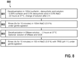
- Fig. 8 shows an exemplary process diagram, for methods 800 for producing natively dried pericardium, which can be carried out between process steps 704 and 705 (as described with reference to Fig. 7 ).
- Step 801 comprises decellularizing the biological material 23 in 100ml in, for example, surfactin-deoxycholic acid solution, for example comprising 0.06% surfactin and 0.5% deoxycholic acid in 0.9% NaCl.
- This process can be performed over a period of 15-30 hours, preferably for 22 hours at a temperature of 30-40°C, preferably at 37°C.
- the solution can be changed after 1 h, 2 h, 3 h, 4 h, etc., preferably after 2 h.
- step 802 rinsing of the biological material 23 in 100 ml of NaCl (e.g., 0.5-1.5%, preferably 0.9%) can be performed with gentle agitation. The rinsing process may be repeated for 2-10 times (preferably six times), and each rinsing process may be performed for 5-15 minutes, preferably 10 minutes.
- step 803 decellularization in DNase solution may follow. This can be done for 1-3 hours (preferably 2 hours) at 30-40°C, preferably at 37°C.
- step 803 can be performed in the presence of a solution of DNase and GCB.
- step 804 rinsing of biological material 23 in 100 ml of NaCl (e.g., 0.5-1.5%, preferably 0.9%) can be performed with gentle agitation. Additionally, TRIS (e.g., at pH 11) may be added to the NaCl solution. Step 805 may be followed by rinsing the biological material 23 for one to five times (preferably once) for 5-20 minutes (preferably 15 minutes) in 100 ml of ethanol (60-80%, preferably 70%) at 30-40°C, preferably at 37°C.
- ethanol 60-80%, preferably 70%
- Fig. 9 shows another exemplary process diagram, for process 900, for producing a biological cover 3 for stent 1 by crosslinking under pressure.
- native dried pericardium can be cut into a geometric shape suitable for the stent 1 using a CO2 laser.
- step 902 forming a (substantially) cylindrical arrangement of the biological material 23 is performed.
- step 903 arranging biological material 23 and insertion of the second material 5(e.g., polyester fabric) in the overlapping areas 4(folds of the biological material 23) is performed.
- assembly into the rigid outer mold e.g., counter element 21
- the pressurizing means 22 e.g., a dilatable tube
- the pressurizing agent can be dilated, e.g., by applying a pressure of 5-15 bar, preferably 10 bar.
- the crosslinking form thus constructed can be placed in DPBS solution.
- the pressure can be reduced to 0.5-2 bar, preferably 1 bar, and after 1-5 minutes, preferably after 1 minute, it can be increased again to e.g. 10 bar.
- glutaraldehyde at a concentration of 0.2-1%, preferably 0.5%) can be added and the biological material 23 can thus be crosslinked (at preferably constant pressure) for a period of 20-30 hours, preferably for 24 hours.
- step 909 the pressure can be released and the biological material 23, rinsed three to five times, preferably three times, for 1-10 minutes, preferably for 5 minutes, in 100ml DPBS with gentle agitation. Stent 1 can then be removed with the biological cover 3 applied and the second material 5 (e.g., the polyester fabric) removed.
- the covered stent thus obtained can be freely post-crosslinked in 0.1-1%, preferably 0.5%, glutaraldehyde for 12 days, preferably changing the solution used every three days.
- drying of the encased stent 1 may subsequently be performed at least partially according to process 700.
- step 912 crimping of the produced biological cover 3 onto a balloon catheter can be performed.
- the product thus obtained can be packaged and finally sterilized in e.g. ETO (ethylene oxide).
- ETO ethylene oxide
Landscapes
- Health & Medical Sciences (AREA)
- Life Sciences & Earth Sciences (AREA)
- Vascular Medicine (AREA)
- Veterinary Medicine (AREA)
- Heart & Thoracic Surgery (AREA)
- Public Health (AREA)
- Animal Behavior & Ethology (AREA)
- General Health & Medical Sciences (AREA)
- Surgery (AREA)
- Epidemiology (AREA)
- Engineering & Computer Science (AREA)
- Biomedical Technology (AREA)
- Chemical & Material Sciences (AREA)
- Transplantation (AREA)
- Cardiology (AREA)
- Oral & Maxillofacial Surgery (AREA)
- Molecular Biology (AREA)
- Chemical Kinetics & Catalysis (AREA)
- Medicinal Chemistry (AREA)
- Gastroenterology & Hepatology (AREA)
- Pulmonology (AREA)
- Prostheses (AREA)
- Materials For Medical Uses (AREA)
- Orthopedics, Nursing, And Contraception (AREA)
Claims (15)
- Verfahren zur Herstellung einer biologischen Ummantelung für einen Stent (3), umfassend:Bereitstellen eines ersten Materials (2) mit einem Hauptkörper (14) in einer zylindrischen Konfiguration und mit mindestens einer Falte in dem ersten Material und mit einem zweiten Material (5), das innerhalb der mindestens einen Falte angeordnet ist, wobei das erste Material (2) ein biologisches Material (23) ist;Pressen des ersten Materials (2) und des zweiten Materials (5) auf ein Gegenelement (21), das außerhalb der zylindrischen Konfiguration angeordnet ist; undAufbringen eines Vernetzungsmittels auf das erste Material (2), dadurch gekennzeichnet, dass das erste Material (2) vernetzbare Gruppen umfasst, die durch Verwendung des Vernetzungsmittels vernetzt werden können, und wobei das zweite Material (2) ein Material ist, das durch Verwendung des Vernetzungsmittels nicht mit dem ersten Material (2) vernetzt werden kann.
- Verfahren nach Anspruch 1, wobei das erste Material (2) mehrere Falten aufweist.
- Verfahren nach Anspruch 1 oder 2, wobei das zweite Material (2) aus einem organischen Polymer hergestellt ist.
- Verfahren nach einem der vorhergehenden Ansprüche, wobei das erste Material (2) ferner mindestens ein Laschenelement (10) und mindestens eine Öffnung (11) aufweist, durch die das jeweilige Laschenelement (10) hindurchtreten kann.
- Verfahren nach Anspruch 4, wobei die mindestens eine Öffnung (11) ein Schlitz ist.
- Verfahren nach Anspruch 4 oder 5, wobei die zylindrische Konfiguration durch Biegen des ersten Materials (2) in die zylindrische Konfiguration und Fixieren der zylindrischen Konfiguration durch Hindurchführen des mindestens einen Laschenelements (10) durch die jeweilige mindestens eine Öffnung (11) zur Bildung einer Laschen-SchlitzVerbindung erhalten wird.
- Verfahren nach einem der Ansprüche 4 bis 6, wobei das mindestens eine Laschenelement (10) einen mittleren Abschnitt aufweist, der mit einem Kopfabschnitt verbunden ist, und wobei der mittlere Abschnitt eine kleinere Größe als der Kopfabschnitt hat und die Größe des mittleren Abschnitts kleiner oder gleich der Größe der jeweiligen mindestens einen Öffnung (11) ist.
- Verfahren nach einem der vorhergehenden Ansprüche, wobei das erste Material (2) außerdem mindestens einen Befestigungsabschnitt (15) aufweist, der aus dem Hauptkörper (14) herausragt.
- Verfahren nach Anspruch 8, wobei der mindestens eine Befestigungsabschnitt (15) an einem Stent (1), vorzugsweise an mindestens einem mechanischen Befestigungselement (17, 18, 19) des Stents, angebracht wird.
- Biologische Ummantelung (3) für einen Stent aus einem biologischen Material (23), vorzugsweise erhalten durch ein Verfahren nach einem der vorhergehenden Ansprüche, umfassend einen Hauptkörper (14) aus dem biologischen Material in einer zylindrischen Konfiguration mit einem ersten Zylinderdurchmesser; und mindestens eine Falte in dem Hauptkörper, wobei die mindestens eine Falte so konfiguriert ist, dass sie sich bei radialer Dilatation des biologischen Materials zumindest teilweise entfaltet, um eine Vergrößerung der zylindrischen Konfiguration auf einen zweiten Zylinderdurchmesser zu ermöglichen, dadurch gekennzeichnet, dass das biologische Material vernetzt ist.
- Biologische Ummantelung (3) nach Anspruch 10, die ferner mindestens ein Laschenelement (10) und mindestens eine Öffnung (11) umfasst, durch die das jeweilige Laschenelement (10) hindurchgeführt werden kann, und wobei das mindestens eine Laschenelement (10) durch die jeweilige mindestens eine Öffnung (11) hindurchgeführt wird, um eine Laschen- und Schlitzverbindung zu bilden.
- Biologische Ummantelung (3) nach Anspruch 11, wobei das Laschenelement (10) relativ zur Öffnung entlang einer Durchgangsrichtung beweglich ist.
- Die biologische Ummantelung (3) nach einem der Ansprüche 10 bis 12, wobei das biologische Material (23) außerdem mindestens einen Befestigungsabschnitt (15) umfasst, der aus dem Hauptkörper (14) herausragt und an einem Stent befestigt werden kann.
- Die biologische Ummantelung (3) nach einem der Ansprüche 10 bis 13, wobei das biologische Material (23) ein kollagenhaltiges Gewebe, vorzugsweise Perikardgewebe, ist.
- Vorrichtung (20) zur Herstellung einer biologischen Abdeckung (3) gemäß dem Verfahren nach einem der Ansprüche 1 bis 9, umfassend ein Gegenelement (21) aus einem Polymerschaum, ein Druckerzeugungsmittel (22), das in ein inneres Lumen (Lu) des zylindrischen biologischen Materials (23) eingeführt werden kann, um das biologische Material (23) auf das Gegenelement (21) zu pressen, wobei das Druckerzeugungsmittel (24) einen anisotropen Druck auf das zylindrische biologische Material (23) ausüben kann.
Priority Applications (1)
| Application Number | Priority Date | Filing Date | Title |
|---|---|---|---|
| EP25177882.5A EP4613295A3 (de) | 2022-04-29 | 2023-04-06 | Biologische abdeckung |
Applications Claiming Priority (2)
| Application Number | Priority Date | Filing Date | Title |
|---|---|---|---|
| DE102022110554 | 2022-04-29 | ||
| EP22178624 | 2022-06-13 |
Related Child Applications (2)
| Application Number | Title | Priority Date | Filing Date |
|---|---|---|---|
| EP25177882.5A Division EP4613295A3 (de) | 2022-04-29 | 2023-04-06 | Biologische abdeckung |
| EP25177882.5A Division-Into EP4613295A3 (de) | 2022-04-29 | 2023-04-06 | Biologische abdeckung |
Publications (4)
| Publication Number | Publication Date |
|---|---|
| EP4279027A2 EP4279027A2 (de) | 2023-11-22 |
| EP4279027A3 EP4279027A3 (de) | 2024-02-07 |
| EP4279027C0 EP4279027C0 (de) | 2025-06-25 |
| EP4279027B1 true EP4279027B1 (de) | 2025-06-25 |
Family
ID=88405084
Family Applications (2)
| Application Number | Title | Priority Date | Filing Date |
|---|---|---|---|
| EP25177882.5A Pending EP4613295A3 (de) | 2022-04-29 | 2023-04-06 | Biologische abdeckung |
| EP23166990.4A Active EP4279027B1 (de) | 2022-04-29 | 2023-04-06 | Biologische abdeckung |
Family Applications Before (1)
| Application Number | Title | Priority Date | Filing Date |
|---|---|---|---|
| EP25177882.5A Pending EP4613295A3 (de) | 2022-04-29 | 2023-04-06 | Biologische abdeckung |
Country Status (2)
| Country | Link |
|---|---|
| US (1) | US20230347024A1 (de) |
| EP (2) | EP4613295A3 (de) |
Families Citing this family (1)
| Publication number | Priority date | Publication date | Assignee | Title |
|---|---|---|---|---|
| CN109260517B (zh) * | 2018-09-19 | 2020-10-30 | 杭州启明医疗器械股份有限公司 | 一种可预装干燥生物心脏瓣膜及其制备方法 |
Family Cites Families (10)
| Publication number | Priority date | Publication date | Assignee | Title |
|---|---|---|---|---|
| ATE164056T1 (de) * | 1993-04-23 | 1998-04-15 | Schneider Europ Ag | Stent mit einer beschichtung aus elastischem material und verfahren zum anbringen der beschichtung auf dem stent |
| US6475232B1 (en) * | 1996-12-10 | 2002-11-05 | Purdue Research Foundation | Stent with reduced thrombogenicity |
| US6361556B1 (en) * | 2000-04-27 | 2002-03-26 | Endovascular Tech Inc | System and method for endovascular aneurysm repair in conjuction with vascular stabilization |
| WO2004017866A1 (en) * | 2002-08-20 | 2004-03-04 | Cook Incorporated | Stent graft with improved proximal end |
| US8998973B2 (en) * | 2004-03-02 | 2015-04-07 | Boston Scientific Scimed, Inc. | Medical devices including metallic films |
| US9205177B2 (en) * | 2009-03-04 | 2015-12-08 | Peytant Solutions, Inc. | Stents modified with material comprising amnion tissue and corresponding processes |
| US20130018450A1 (en) * | 2011-07-13 | 2013-01-17 | Hunt James B | Prosthesis delivery system with retention sleeve |
| US9770352B2 (en) * | 2013-03-14 | 2017-09-26 | W. L. Gore & Associates, Inc. | Inflatable balloon and cover |
| US9855371B2 (en) * | 2014-04-28 | 2018-01-02 | John James Scanlon | Bioresorbable stent |
| US20200054435A1 (en) * | 2018-08-16 | 2020-02-20 | Cook Medical Technologies Llc | Graft material with internal folds and method of use thereof |
-
2023
- 2023-04-06 EP EP25177882.5A patent/EP4613295A3/de active Pending
- 2023-04-06 EP EP23166990.4A patent/EP4279027B1/de active Active
- 2023-04-20 US US18/303,912 patent/US20230347024A1/en active Pending
Also Published As
| Publication number | Publication date |
|---|---|
| EP4613295A3 (de) | 2025-12-03 |
| EP4613295A2 (de) | 2025-09-10 |
| EP4279027C0 (de) | 2025-06-25 |
| US20230347024A1 (en) | 2023-11-02 |
| EP4279027A3 (de) | 2024-02-07 |
| EP4279027A2 (de) | 2023-11-22 |
Similar Documents
| Publication | Publication Date | Title |
|---|---|---|
| US7806921B2 (en) | Monocusp valve design | |
| US8057532B2 (en) | Implantable frame and valve design | |
| JP5575931B2 (ja) | 経皮的に送達可能な心臓弁およびこれに関連する方法 | |
| US9192473B2 (en) | Valve frame | |
| CA2267408C (en) | Tubular submucosal graft constructs | |
| US8177837B2 (en) | Percutaneously deployed vascular valves | |
| JP2013521060A5 (de) | ||
| EP4279027B1 (de) | Biologische abdeckung | |
| US20230398261A1 (en) | Process for seamless connecting/joining of tissue comprising crosslinkable groups | |
| WO2022090419A1 (en) | Process for the treatment of non-crosslinked tissue | |
| EP4237026B1 (de) | Verfahren zur herstellung von vernetztem und optional geformtem gewebe mit selektiver einstellung von dicke, form und/oder flexibilität | |
| EP4236870B1 (de) | Verfahren zur dreidimensionalen formgebung eines gewebes oder einer gewebekomponente | |
| EP4514413B1 (de) | Verfahren zur herstellung von biologischem gewebe | |
| AU774634B2 (en) | Tubular submucosal graft constructs | |
| HK1237635A1 (en) | Implantable devices comprising graft membranes |
Legal Events
| Date | Code | Title | Description |
|---|---|---|---|
| PUAI | Public reference made under article 153(3) epc to a published international application that has entered the european phase |
Free format text: ORIGINAL CODE: 0009012 |
|
| STAA | Information on the status of an ep patent application or granted ep patent |
Free format text: STATUS: THE APPLICATION HAS BEEN PUBLISHED |
|
| AK | Designated contracting states |
Kind code of ref document: A2 Designated state(s): AL AT BE BG CH CY CZ DE DK EE ES FI FR GB GR HR HU IE IS IT LI LT LU LV MC ME MK MT NL NO PL PT RO RS SE SI SK SM TR |
|
| PUAL | Search report despatched |
Free format text: ORIGINAL CODE: 0009013 |
|
| AK | Designated contracting states |
Kind code of ref document: A3 Designated state(s): AL AT BE BG CH CY CZ DE DK EE ES FI FR GB GR HR HU IE IS IT LI LT LU LV MC ME MK MT NL NO PL PT RO RS SE SI SK SM TR |
|
| RIC1 | Information provided on ipc code assigned before grant |
Ipc: A61L 31/14 20060101ALI20231229BHEP Ipc: A61L 31/00 20060101ALI20231229BHEP Ipc: A61F 2/82 20130101ALI20231229BHEP Ipc: A61F 2/92 20130101ALI20231229BHEP Ipc: A61F 2/07 20130101AFI20231229BHEP |
|
| STAA | Information on the status of an ep patent application or granted ep patent |
Free format text: STATUS: REQUEST FOR EXAMINATION WAS MADE |
|
| 17P | Request for examination filed |
Effective date: 20240725 |
|
| RBV | Designated contracting states (corrected) |
Designated state(s): AL AT BE BG CH CY CZ DE DK EE ES FI FR GB GR HR HU IE IS IT LI LT LU LV MC ME MK MT NL NO PL PT RO RS SE SI SK SM TR |
|
| GRAP | Despatch of communication of intention to grant a patent |
Free format text: ORIGINAL CODE: EPIDOSNIGR1 |
|
| STAA | Information on the status of an ep patent application or granted ep patent |
Free format text: STATUS: GRANT OF PATENT IS INTENDED |
|
| RIC1 | Information provided on ipc code assigned before grant |
Ipc: A61L 31/16 20060101ALI20250115BHEP Ipc: A61L 31/04 20060101ALI20250115BHEP Ipc: A61L 31/14 20060101ALI20250115BHEP Ipc: A61L 31/00 20060101ALI20250115BHEP Ipc: A61F 2/82 20130101ALI20250115BHEP Ipc: A61F 2/92 20130101ALI20250115BHEP Ipc: A61F 2/07 20130101AFI20250115BHEP |
|
| INTG | Intention to grant announced |
Effective date: 20250204 |
|
| GRAS | Grant fee paid |
Free format text: ORIGINAL CODE: EPIDOSNIGR3 |
|
| GRAA | (expected) grant |
Free format text: ORIGINAL CODE: 0009210 |
|
| STAA | Information on the status of an ep patent application or granted ep patent |
Free format text: STATUS: THE PATENT HAS BEEN GRANTED |
|
| AK | Designated contracting states |
Kind code of ref document: B1 Designated state(s): AL AT BE BG CH CY CZ DE DK EE ES FI FR GB GR HR HU IE IS IT LI LT LU LV MC ME MK MT NL NO PL PT RO RS SE SI SK SM TR |
|
| REG | Reference to a national code |
Ref country code: GB Ref legal event code: FG4D |
|
| REG | Reference to a national code |
Ref country code: CH Ref legal event code: EP |
|
| REG | Reference to a national code |
Ref country code: CH Ref legal event code: EP |
|
| REG | Reference to a national code |
Ref country code: IE Ref legal event code: FG4D |
|
| U01 | Request for unitary effect filed |
Effective date: 20250625 |
|
| U07 | Unitary effect registered |
Designated state(s): AT BE BG DE DK EE FI FR IT LT LU LV MT NL PT RO SE SI Effective date: 20250701 |
|
| PG25 | Lapsed in a contracting state [announced via postgrant information from national office to epo] |
Ref country code: GR Free format text: LAPSE BECAUSE OF FAILURE TO SUBMIT A TRANSLATION OF THE DESCRIPTION OR TO PAY THE FEE WITHIN THE PRESCRIBED TIME-LIMIT Effective date: 20250926 Ref country code: NO Free format text: LAPSE BECAUSE OF FAILURE TO SUBMIT A TRANSLATION OF THE DESCRIPTION OR TO PAY THE FEE WITHIN THE PRESCRIBED TIME-LIMIT Effective date: 20250925 |
|
| PG25 | Lapsed in a contracting state [announced via postgrant information from national office to epo] |
Ref country code: HR Free format text: LAPSE BECAUSE OF FAILURE TO SUBMIT A TRANSLATION OF THE DESCRIPTION OR TO PAY THE FEE WITHIN THE PRESCRIBED TIME-LIMIT Effective date: 20250625 |
|
| PG25 | Lapsed in a contracting state [announced via postgrant information from national office to epo] |
Ref country code: RS Free format text: LAPSE BECAUSE OF FAILURE TO SUBMIT A TRANSLATION OF THE DESCRIPTION OR TO PAY THE FEE WITHIN THE PRESCRIBED TIME-LIMIT Effective date: 20250925 |
|
| PG25 | Lapsed in a contracting state [announced via postgrant information from national office to epo] |
Ref country code: IS Free format text: LAPSE BECAUSE OF FAILURE TO SUBMIT A TRANSLATION OF THE DESCRIPTION OR TO PAY THE FEE WITHIN THE PRESCRIBED TIME-LIMIT Effective date: 20251025 |
|
| PG25 | Lapsed in a contracting state [announced via postgrant information from national office to epo] |
Ref country code: SM Free format text: LAPSE BECAUSE OF FAILURE TO SUBMIT A TRANSLATION OF THE DESCRIPTION OR TO PAY THE FEE WITHIN THE PRESCRIBED TIME-LIMIT Effective date: 20250625 |
|
| PG25 | Lapsed in a contracting state [announced via postgrant information from national office to epo] |
Ref country code: CZ Free format text: LAPSE BECAUSE OF FAILURE TO SUBMIT A TRANSLATION OF THE DESCRIPTION OR TO PAY THE FEE WITHIN THE PRESCRIBED TIME-LIMIT Effective date: 20250625 |
|
| PG25 | Lapsed in a contracting state [announced via postgrant information from national office to epo] |
Ref country code: PL Free format text: LAPSE BECAUSE OF FAILURE TO SUBMIT A TRANSLATION OF THE DESCRIPTION OR TO PAY THE FEE WITHIN THE PRESCRIBED TIME-LIMIT Effective date: 20250625 |
|
| PG25 | Lapsed in a contracting state [announced via postgrant information from national office to epo] |
Ref country code: SK Free format text: LAPSE BECAUSE OF FAILURE TO SUBMIT A TRANSLATION OF THE DESCRIPTION OR TO PAY THE FEE WITHIN THE PRESCRIBED TIME-LIMIT Effective date: 20250625 |
|
| PG25 | Lapsed in a contracting state [announced via postgrant information from national office to epo] |
Ref country code: ES Free format text: LAPSE BECAUSE OF FAILURE TO SUBMIT A TRANSLATION OF THE DESCRIPTION OR TO PAY THE FEE WITHIN THE PRESCRIBED TIME-LIMIT Effective date: 20250625 |
|
| PLBE | No opposition filed within time limit |
Free format text: ORIGINAL CODE: 0009261 |
|
| STAA | Information on the status of an ep patent application or granted ep patent |
Free format text: STATUS: NO OPPOSITION FILED WITHIN TIME LIMIT |