EP4279033A2 - Unité d'entraînement extracorporelle pour un système d'implant à longueur extra-corporel réglable et système d'implant à longueur réglable - Google Patents
Unité d'entraînement extracorporelle pour un système d'implant à longueur extra-corporel réglable et système d'implant à longueur réglable Download PDFInfo
- Publication number
- EP4279033A2 EP4279033A2 EP23201401.9A EP23201401A EP4279033A2 EP 4279033 A2 EP4279033 A2 EP 4279033A2 EP 23201401 A EP23201401 A EP 23201401A EP 4279033 A2 EP4279033 A2 EP 4279033A2
- Authority
- EP
- European Patent Office
- Prior art keywords
- extracorporeal
- magnetic ring
- drive unit
- magnetic
- ring
- Prior art date
- Legal status (The legal status is an assumption and is not a legal conclusion. Google has not performed a legal analysis and makes no representation as to the accuracy of the status listed.)
- Pending
Links
Images



Classifications
-
- A—HUMAN NECESSITIES
- A61—MEDICAL OR VETERINARY SCIENCE; HYGIENE
- A61B—DIAGNOSIS; SURGERY; IDENTIFICATION
- A61B34/00—Computer-aided surgery; Manipulators or robots specially adapted for use in surgery
- A61B34/70—Manipulators specially adapted for use in surgery
- A61B34/73—Manipulators for magnetic surgery
-
- A—HUMAN NECESSITIES
- A61—MEDICAL OR VETERINARY SCIENCE; HYGIENE
- A61B—DIAGNOSIS; SURGERY; IDENTIFICATION
- A61B17/00—Surgical instruments, devices or methods
- A61B17/56—Surgical instruments or methods for treatment of bones or joints; Devices specially adapted therefor
- A61B17/58—Surgical instruments or methods for treatment of bones or joints; Devices specially adapted therefor for osteosynthesis, e.g. bone plates, screws or setting implements
- A61B17/68—Internal fixation devices, including fasteners and spinal fixators, even if a part thereof projects from the skin
- A61B17/72—Intramedullary devices, e.g. pins or nails
- A61B17/7216—Intramedullary devices, e.g. pins or nails for bone lengthening or compression
-
- A—HUMAN NECESSITIES
- A61—MEDICAL OR VETERINARY SCIENCE; HYGIENE
- A61F—FILTERS IMPLANTABLE INTO BLOOD VESSELS; PROSTHESES; DEVICES PROVIDING PATENCY TO, OR PREVENTING COLLAPSING OF, TUBULAR STRUCTURES OF THE BODY, e.g. STENTS; ORTHOPAEDIC, NURSING OR CONTRACEPTIVE DEVICES; FOMENTATION; TREATMENT OR PROTECTION OF EYES OR EARS; BANDAGES, DRESSINGS OR ABSORBENT PADS; FIRST-AID KITS
- A61F2/00—Filters implantable into blood vessels; Prostheses, i.e. artificial substitutes or replacements for parts of the body; Appliances for connecting them with the body; Devices providing patency to, or preventing collapsing of, tubular structures of the body, e.g. stents
- A61F2/02—Prostheses implantable into the body
- A61F2/28—Bones
-
- A—HUMAN NECESSITIES
- A61—MEDICAL OR VETERINARY SCIENCE; HYGIENE
- A61B—DIAGNOSIS; SURGERY; IDENTIFICATION
- A61B17/00—Surgical instruments, devices or methods
- A61B2017/00367—Details of actuation of instruments, e.g. relations between pushing buttons, or the like, and activation of the tool, working tip, or the like
- A61B2017/00411—Details of actuation of instruments, e.g. relations between pushing buttons, or the like, and activation of the tool, working tip, or the like actuated by application of energy from an energy source outside the body
-
- A—HUMAN NECESSITIES
- A61—MEDICAL OR VETERINARY SCIENCE; HYGIENE
- A61B—DIAGNOSIS; SURGERY; IDENTIFICATION
- A61B17/00—Surgical instruments, devices or methods
- A61B17/56—Surgical instruments or methods for treatment of bones or joints; Devices specially adapted therefor
- A61B17/58—Surgical instruments or methods for treatment of bones or joints; Devices specially adapted therefor for osteosynthesis, e.g. bone plates, screws or setting implements
- A61B17/68—Internal fixation devices, including fasteners and spinal fixators, even if a part thereof projects from the skin
- A61B2017/681—Alignment, compression, or distraction mechanisms
-
- A—HUMAN NECESSITIES
- A61—MEDICAL OR VETERINARY SCIENCE; HYGIENE
- A61F—FILTERS IMPLANTABLE INTO BLOOD VESSELS; PROSTHESES; DEVICES PROVIDING PATENCY TO, OR PREVENTING COLLAPSING OF, TUBULAR STRUCTURES OF THE BODY, e.g. STENTS; ORTHOPAEDIC, NURSING OR CONTRACEPTIVE DEVICES; FOMENTATION; TREATMENT OR PROTECTION OF EYES OR EARS; BANDAGES, DRESSINGS OR ABSORBENT PADS; FIRST-AID KITS
- A61F2/00—Filters implantable into blood vessels; Prostheses, i.e. artificial substitutes or replacements for parts of the body; Appliances for connecting them with the body; Devices providing patency to, or preventing collapsing of, tubular structures of the body, e.g. stents
- A61F2/02—Prostheses implantable into the body
- A61F2/28—Bones
- A61F2002/2825—Femur
-
- A—HUMAN NECESSITIES
- A61—MEDICAL OR VETERINARY SCIENCE; HYGIENE
- A61F—FILTERS IMPLANTABLE INTO BLOOD VESSELS; PROSTHESES; DEVICES PROVIDING PATENCY TO, OR PREVENTING COLLAPSING OF, TUBULAR STRUCTURES OF THE BODY, e.g. STENTS; ORTHOPAEDIC, NURSING OR CONTRACEPTIVE DEVICES; FOMENTATION; TREATMENT OR PROTECTION OF EYES OR EARS; BANDAGES, DRESSINGS OR ABSORBENT PADS; FIRST-AID KITS
- A61F2/00—Filters implantable into blood vessels; Prostheses, i.e. artificial substitutes or replacements for parts of the body; Appliances for connecting them with the body; Devices providing patency to, or preventing collapsing of, tubular structures of the body, e.g. stents
- A61F2/02—Prostheses implantable into the body
- A61F2/30—Joints
- A61F2002/30001—Additional features of subject-matter classified in A61F2/28, A61F2/30 and subgroups thereof
- A61F2002/30316—The prosthesis having different structural features at different locations within the same prosthesis; Connections between prosthetic parts; Special structural features of bone or joint prostheses not otherwise provided for
- A61F2002/30535—Special structural features of bone or joint prostheses not otherwise provided for
- A61F2002/30537—Special structural features of bone or joint prostheses not otherwise provided for adjustable
- A61F2002/3055—Special structural features of bone or joint prostheses not otherwise provided for adjustable for adjusting length
-
- A—HUMAN NECESSITIES
- A61—MEDICAL OR VETERINARY SCIENCE; HYGIENE
- A61F—FILTERS IMPLANTABLE INTO BLOOD VESSELS; PROSTHESES; DEVICES PROVIDING PATENCY TO, OR PREVENTING COLLAPSING OF, TUBULAR STRUCTURES OF THE BODY, e.g. STENTS; ORTHOPAEDIC, NURSING OR CONTRACEPTIVE DEVICES; FOMENTATION; TREATMENT OR PROTECTION OF EYES OR EARS; BANDAGES, DRESSINGS OR ABSORBENT PADS; FIRST-AID KITS
- A61F2/00—Filters implantable into blood vessels; Prostheses, i.e. artificial substitutes or replacements for parts of the body; Appliances for connecting them with the body; Devices providing patency to, or preventing collapsing of, tubular structures of the body, e.g. stents
- A61F2/02—Prostheses implantable into the body
- A61F2/30—Joints
- A61F2002/30001—Additional features of subject-matter classified in A61F2/28, A61F2/30 and subgroups thereof
- A61F2002/30316—The prosthesis having different structural features at different locations within the same prosthesis; Connections between prosthetic parts; Special structural features of bone or joint prostheses not otherwise provided for
- A61F2002/30535—Special structural features of bone or joint prostheses not otherwise provided for
- A61F2002/30601—Special structural features of bone or joint prostheses not otherwise provided for telescopic
-
- A—HUMAN NECESSITIES
- A61—MEDICAL OR VETERINARY SCIENCE; HYGIENE
- A61F—FILTERS IMPLANTABLE INTO BLOOD VESSELS; PROSTHESES; DEVICES PROVIDING PATENCY TO, OR PREVENTING COLLAPSING OF, TUBULAR STRUCTURES OF THE BODY, e.g. STENTS; ORTHOPAEDIC, NURSING OR CONTRACEPTIVE DEVICES; FOMENTATION; TREATMENT OR PROTECTION OF EYES OR EARS; BANDAGES, DRESSINGS OR ABSORBENT PADS; FIRST-AID KITS
- A61F2/00—Filters implantable into blood vessels; Prostheses, i.e. artificial substitutes or replacements for parts of the body; Appliances for connecting them with the body; Devices providing patency to, or preventing collapsing of, tubular structures of the body, e.g. stents
- A61F2/02—Prostheses implantable into the body
- A61F2/30—Joints
- A61F2002/30001—Additional features of subject-matter classified in A61F2/28, A61F2/30 and subgroups thereof
- A61F2002/30667—Features concerning an interaction with the environment or a particular use of the prosthesis
- A61F2002/30668—Means for transferring electromagnetic energy to implants
-
- A—HUMAN NECESSITIES
- A61—MEDICAL OR VETERINARY SCIENCE; HYGIENE
- A61F—FILTERS IMPLANTABLE INTO BLOOD VESSELS; PROSTHESES; DEVICES PROVIDING PATENCY TO, OR PREVENTING COLLAPSING OF, TUBULAR STRUCTURES OF THE BODY, e.g. STENTS; ORTHOPAEDIC, NURSING OR CONTRACEPTIVE DEVICES; FOMENTATION; TREATMENT OR PROTECTION OF EYES OR EARS; BANDAGES, DRESSINGS OR ABSORBENT PADS; FIRST-AID KITS
- A61F2/00—Filters implantable into blood vessels; Prostheses, i.e. artificial substitutes or replacements for parts of the body; Appliances for connecting them with the body; Devices providing patency to, or preventing collapsing of, tubular structures of the body, e.g. stents
- A61F2/02—Prostheses implantable into the body
- A61F2/30—Joints
- A61F2002/30001—Additional features of subject-matter classified in A61F2/28, A61F2/30 and subgroups thereof
- A61F2002/30667—Features concerning an interaction with the environment or a particular use of the prosthesis
- A61F2002/30706—Features concerning an interaction with the environment or a particular use of the prosthesis specially designed for children, e.g. having means for adjusting to their growth
-
- A—HUMAN NECESSITIES
- A61—MEDICAL OR VETERINARY SCIENCE; HYGIENE
- A61F—FILTERS IMPLANTABLE INTO BLOOD VESSELS; PROSTHESES; DEVICES PROVIDING PATENCY TO, OR PREVENTING COLLAPSING OF, TUBULAR STRUCTURES OF THE BODY, e.g. STENTS; ORTHOPAEDIC, NURSING OR CONTRACEPTIVE DEVICES; FOMENTATION; TREATMENT OR PROTECTION OF EYES OR EARS; BANDAGES, DRESSINGS OR ABSORBENT PADS; FIRST-AID KITS
- A61F2/00—Filters implantable into blood vessels; Prostheses, i.e. artificial substitutes or replacements for parts of the body; Appliances for connecting them with the body; Devices providing patency to, or preventing collapsing of, tubular structures of the body, e.g. stents
- A61F2/02—Prostheses implantable into the body
- A61F2/30—Joints
- A61F2/46—Special tools for implanting artificial joints
- A61F2002/4688—Special tools for implanting artificial joints having operating or control means
- A61F2002/4698—Special tools for implanting artificial joints having operating or control means magnetic
Definitions
- the invention relates to an externally (extracorporeally) adjustable system for adjusting the length of an implant component as part of an endoprosthesis and an adjusting device therefor.
- the adjusting device is intended for a prosthetic shaft of the implant component, which is designed for attachment to a bone to be lengthened, and comprises mutually displaceable fastening parts, each of which is to be arranged on a part of the bone to be lengthened, as well as an adjusting element driven by a drive element, which does this is designed to distract the two mutually displaceable fastening parts.
- Intracorporeally adjustable prostheses are important for applications in which prostheses are supposed to grow with you, so to speak. They are particularly indicated in cases where a correspondingly longer prosthesis is required either due to natural processes, such as the growth of children, but also for applications in which bone formation (osteogenesis) occurs along a separation or fracture point is noticeably stretched further in order to continuously stimulate the formation of new cells.
- the two bone parts created by the separation point are successively separated moved away, for example by 1 mm per day, in order to constantly stimulate the formation of new bone tissue.
- an extremity such as a leg, can be lengthened. This is important in order to equalize the length of a person's two legs.
- the bone supplied with the prosthesis can become longer in a similar way to the natural growth process of children or adolescents .
- implantable prostheses have been developed that enable the desired length adjustment using an intracorporeally implanted prosthesis.
- the actual length adjustment can be done invasively, especially with a purely mechanical length adjustment, or by means of a drive implanted on the prosthesis that is remotely controlled from the outside (Mutars system from the German company Implantcast GmbH, Synoste system from the Finnish company Synoste Oy).
- the prosthesis contains an electric motor or forms part of an electric motor that can be controlled from the outside (extracorporeally). If necessary, it can also be supplied with energy from outside.
- This is such a structure with a, so to speak, distributed electric motor known, in which the prosthesis and its adjustment element form part of an electric motor (so to speak the rotor), and the other part with the excitation (so to speak the stator) is formed by an extracorporeal attachment ( WO 01/786141 ).
- the actual electric motor is basically arranged partly intracorporeally (with its rotor) and partly extracorporeally (with its stator).
- Such an electric motor-based system is easy to operate, but incorrect operation is also relatively easy. Sufficient extracorporeal adjustability can thus be achieved, but skilled personnel are required for operation due to the risk of operating errors, whereby the electric motor with a large adjustment force causes incorrect adjustment that is dangerous for the patient.
- the approval of such a system is therefore complex and difficult.
- the application can usually only be carried out by specialist personnel, which causes additional effort. This leads to coordination problems with regard to the required appointments on which the specialist staff has time to treat (outpatient) patients, or leads to (over)large adjustment units (in cm of adjustment per appointment) in order to minimize the number of patient visits (albeit at the price of possibly medically questionably large adjustment units per appointment).
- the invention is based on the object of creating an improved system that allows extracorporeal actuation and is easier to handle.
- an extracorporeal drive unit for an extracorporeally length-adjustable implant system
- the extracorporeal drive unit being designed to actuate the drive element by means of a magnetic field
- the object is achieved in that the extracorporeal drive unit has an extracorporeal magnetic ring and has an actuating device, wherein the extracorporeal magnetic ring is rotatably mounted about an axis of rotation of the magnetic ring, which runs perpendicular to a ring plane of the extracorporeal magnetic ring, the extracorporeal magnetic ring having an interior space for receiving a bone to be lengthened is formed with the adjusting device, the actuating device being designed for this purpose is to mechanically rotate the extracorporeal magnetic ring about the inner axis, the extracorporeal magnetic ring having permanent magnets which generate a directed static magnetic field in the interior that is fixed to the ring.
- Ring-fixed means an arrangement that is fixed in relation to the ring and rotates with the ring.
- Directional is understood to mean a typically uniform orientation of a magnetic field.
- the orientation of the magnetic field should have the same direction at every point in the field.
- An essentially uniform magnetic field is referred to as “homogeneous” in which local deviations in field strength in a central area comprising at least 80% of the entire area amount to at most +/- 10% of the mean value.
- Static means a magnetic field of constant strength. In particular, it forms a contrast to the typically rapidly changing electromagnetic fields.
- the invention is based on the idea of moving away from the electric motor-operated concept and instead providing mechanical actuation.
- the invention achieves this by providing a static magnetic field by means of the magnetic ring, which can be rotated mechanically (manually or by motor).
- the magnetic ring as a whole is rotated by the actuating device.
- the permanent magnet which acts as a drive element within the implant component, always aligns itself according to the static magnetic field of the magnetic ring.
- the position of the permanent magnet functioning as a drive element within the adjusting device results from the position or the rotation of the static magnetic field.
- the invention achieves significant simplification and precise position control over the position of the permanent magnet acting as a drive element.
- a simple manual operation can be enough; Electricity is no longer required for operation.
- the system according to the invention with its drive unit based on a static magnetic field, can therefore also be operated by assistants or laypeople, basically also by the patient himself.
- the invention with the rotatable magnetic ring allows precise control over the alignment of the static magnetic field. In this way, a fine adjustment of the angular position of the drive element of the adjusting device can be achieved, which enables a very precise adjustment of the adjustment achieved.
- the invention thus achieves an increase in the adjustment reliability in an incredibly simple manner while at the same time simplifying the drive unit, which makes it suitable for laypeople and patients.
- the magnetic ring is preferably divisible into at least two segments in order to create openable and closable access for a body part provided with the prosthesis shaft, in particular a leg or arm, to the interior of the magnetic ring.
- the drive unit can be easily positioned in the area of the thigh of a patient in order to adjust the implant component arranged in the shaft of an implant component in the femur.
- the rest of the drive unit is designed in such a way that when the magnetic ring is opened, free access to its interior is possible. The application is made considerably easier thanks to the hinged magnetic ring.
- the opening of the magnetic ring is neither prevented nor promoted by the magnetic force of the magnets arranged in the magnetic ring.
- the magnetic ring is designed so that it can be opened without magnetic force.
- Magnetic force-free is understood here to mean that the force directed by the magnetic force against opening is either zero or so small that an operator can easily overcome it by hand, in particular without the use of tools.
- a separating plane between the segments is advantageously chosen so that it extends in the direction of the directed static magnetic field. This ensures that components of the magnetic force running transversely to the parting plane are minimized.
- the segments are preferably connected with connecting means, of which at least one can be opened and reclosed and at least one can be folded like a hinge. Thanks to these connecting means, the segments can be easily opened and closed again after placing the affected extremity (that is the part of the body in which the implant component with the adjusting device according to the invention is contained, in particular an arm or a leg). In which one of the connecting means has a hinge-like foldability If this is possible, complete removal of the openable segment can be avoided (although this would also be possible in principle). This makes handling even easier.
- the magnetic ring In the open, unfolded state, the magnetic ring is preferably secured against (unwanted) movement.
- a locking device is expediently provided which fixes the magnetic ring with its segments in the open position so that it cannot rotate. This effectively counteracts the risk of an unplanned movement of the magnetic ring, which could also lead to an undesirable closure.
- a safety device is provided, which is designed in particular by means of a positive guide to effect a coupling of the magnet ring in the closed position. This prevents the magnetic ring from opening outside of the opening position. This reliably prevents unwanted opening of the magnetic ring, for example during normal operation.
- the magnetic ring is designed with permanent magnets. It is expediently formed by a large number of sub-magnets which are arranged on the magnetic ring. This enables the use of commercially available and therefore cost-effective typical permanent magnets as sub-magnets. This means that even relatively large magnetic rings can be manufactured efficiently and with relatively little weight.
- the individual sub-magnets, individual magnets are preferably similar, in particular designed as magnetic dipole bodies, preferably made of rare earth metals (so-called rare earth magnets).
- the sub-magnets are preferably inserted at regular angles along the magnetic ring with different field orientations. The angle-fixed arrangement keeps the sub-magnets in place always maintains their field orientation in the magnetic ring.
- the sub-magnets are expediently arranged in such a way that their magnetic field (more precisely, the stray fields outside the sub-magnets) is maximally compensated for each other along a separating plane between segments of the magnetic ring. This means that the magnetic field across the parting plane can be minimized. This is a particularly advantageous way to achieve in a simple and reliable manner that the segments can be opened without magnetic force, as already explained above.
- a housing is advantageously provided for the drive unit, which surrounds the magnetic ring.
- the housing magnetic fields outside the magnetic ring, in particular stray fields, are short-circuited, so that the external space surrounding the housing is largely free of magnetic fields (“outside field-free”).
- the housing has one or more shields and/or is preferably made of soft magnetic material. This means that there is no external influence from the magnetic field of the magnetic ring (which is quite strong inside). This makes safe transport much easier.
- the drive unit is expediently provided with a positioning device which acts on the magnetic ring, in particular a counter which displays revolutions of the magnetic ring.
- a positioning device which acts on the magnetic ring
- a counter which displays revolutions of the magnetic ring.
- This allows the position of the magnetic ring to be displayed, allowing the user to make fine and precise adjustments.
- This applies to both the angular position of the magnetic ring and the number of revolutions of the magnetic ring.
- the operator can be shown information about the adjustment distance of the adjustment device, which has been effected with the drive device, in an easily readable and reproducible manner by means of a counter.
- An extracorporeal locking switch can also advantageously be provided, which is preferably arranged on the drive unit and acts on an adjustment locking element arranged on the prosthesis shaft.
- the adjustment element of the implant component can thus be locked against unintentional adjustment by means of the adjustment locking element. If an adjustment with the drive unit is provided, the adjustment locking element is released by means of the locking switch, and thus the adjustment element is released again in order to be able to carry out the desired adjustment using the drive unit.
- the drive unit is preferably provided with a base. It holds the drive unit in an upright position and at the same time acts as a tilt protection to maintain correct relative positioning of the drive unit to the implant component.
- the base is preferably further provided with a direction-oriented receptacle for the body part, in particular arm or leg, into which the implant component with the adjusting device is implanted.
- the invention further extends to the implant component with the adjustment device itself, as described above for the system.
- the invention also extends to such an implant component in which the adjusting device is designed such that a drive element with a rotatably arranged permanent magnet acts on a spindle drive via a gear to convert a rotary movement of the permanent magnet into a distracting longitudinal movement, the drive element being used for actuation is formed by means of a magnetic field of an extracorporeal drive unit, and with particular advantage a bending rod is provided for power transmission from the drive element to the spindle drive.
- the implant component can be prevented from bending under load be balanced.
- the bending rod makes it possible to compensate for an angular error between the drive element with the gear (reduction gear) on the one hand and the actual spindle drive on the other.
- Such an angular error arises in particular because the implant component bends under high load.
- the fastening parts that move relative to one another typically the inner and outer tubes of a telescopic adjustment mechanism, are bent transversely to their central axis under load. There is then a risk that the actual drive element with the gearbox will no longer be exactly aligned with the axis of the spindle drive with respect to its axis.
- the invention has recognized that this can be reliably prevented in an incredibly simple manner by means of a bending rod between the drive element and gear on the one hand and the spindle drive on the other. This means there is no risk of the adjusting element blocking, even under high loads.
- the drive spindle expediently has a central bore that is open on one side and into which the bending rod is inserted.
- a coupling between the free end of the bending bar and the drive spindle is preferably provided at the bottom of the central bore.
- the bending rod has a length that is preferably at least a third, more preferably at least a half, of the length of the drive spindle, and in particular is designed to accommodate an angular offset of up to +/- 5 degrees.
- the bending rod is advantageously designed to be laterally constricted along its main part. On the one hand, this facilitates the desired bending of the bending rod and, on the other hand, ensures the required clearance of the bending rod in the central bore.
- a system for adjusting the length of an implanted prosthesis and the adjustment device for this is in the form of a first exemplary embodiment in Figure 1 shown schematically.
- a leg 9 which has a bone 90 to be lengthened, in the form of a femur bone. It is divided into two parts 91, 92, with the implant component 1 being anchored in both parts and thus connecting the two parts 91, 92 of the femur bone 90 to one another.
- the implant component 1 according to the invention can be a length-adjustable shaft of a prosthesis system, as shown, for example, in Figure 16 is shown.
- the implant component 1 has a cone connector at both ends, preferably a male cone connector 11 at one end and a female cone connector 12 at the other end (it goes without saying that other forms of connection are also possible, for example using threads etc.).
- the implant component can in particular be a part of a larger joint endoprosthesis, in particular for a total replacement of the femur bone 90.
- the ends of the implant component 1 with the cone connectors 11, 12 can be moved away from each other, ie the length of the implant component 1 can be changed, in particular increased.
- An extracorporeal drive unit 7 is provided to operate the adjusting device 2.
- the magnetic ring 8 comprises a magnet ring 8, which is rotatably held and guided within a carrier 70.
- the magnetic ring 8 is designed in such a way that a directed static magnetic field is created in its interior 80.
- a directed static magnetic field 88 is in Figure 2 shown.
- the magnetic ring 8 is not designed as a unitary solid body, but rather is constructed discretely, namely from a large number of sub-magnets 85.
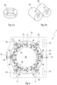
- the sub-magnets 85 are each designed as a magnetic dipole, which means that the actual magnetic body points to one side a north pole "N" on the other side a south pole "S" (this is in Figure 3a indicated by different shades of gray).
- the arrangement of the north pole and south pole remains basically unchanged (this is in Figure 3b shown, with the direction of the remanent magnetization 87 highlighted by a black arrow). This also results in a specific magnetic orientation.
- the sub-magnets 85 are dipole magnets 86, which have a directed magnetic field inside, as in Figure 3b is clearly shown.
- the invention makes use of this characteristic of the sub-magnets 85 and thus creates a directed static magnetic field with a manageable number (namely 16) of sub-magnets 85, which is also largely homogeneous (see Figure 2 ).
- “homogeneous” is understood to mean that, viewed over the surface of the interior 80, there is a location-dependent deviation in the magnetic field strength, which is not greater than +/- 15% of the actual average magnetic field strength. This is achieved by a specific angular orientation of the sub-magnets 85 in the magnetic ring 8.
- the sub-magnets 85 are arranged equidistant from the center, that is, ideally a uniform circle results.
- the sub-magnets 85 are inserted into the magnetic ring 8 with different orientations.
- the magnetic ring 8 By actuating the magnetic ring 8, in particular by means of a manual actuating device 75, the magnetic ring 8 together with its sub-magnets 85 are brought into a rotational movement in the ring plane, as a result of which the directed static magnetic field 88 also rotates accordingly.
- the manual actuating device 75 can be designed as a handle 75 or an easy-to-grip coating on the lateral surface of the magnetic ring 8, but if necessary, mechanization can also be carried out using a servo drive (not shown). be seen. Based on a permanent magnet as the drive element 3, the angular position of the drive of the adjusting device 2 and the currently achieved adjustment path can be determined easily and safely by slowly rotating the magnetic ring 8 with its static magnetic field 88.
- the drive unit 7 thus enables simple but precise control and control of the actual position of the permanent magnet, which in turn results in the current angular position of the drive of the adjusting device 2, even with the manual adjustment of the magnetic ring 8 by means of the actuating element 75. Because of the strength of the magnetic field generated in the cavity 80 of the magnetic ring 8 and the design as a static, ie consistently strong (although possibly slowly rotating) magnetic field, slip that impairs the positioning accuracy practically does not occur thanks to this arrangement. In this regard, it can be made easier for the user to record the adjustment path achieved by optionally arranging a counter 66 on the drive unit 7, which monitors the number of revolutions of the magnetic ring 8 in the drive unit 7 and displays it to the user. Because of the precise transmission of the rotational movement of the magnetic ring 8 to the permanent magnet in the drive of the implant component 1, a clear measure is given for the adjustment distance effected by the adjusting device 2 of the implant component 1.
- the drive unit provided in its entirety with the reference number 7, comprises a carrier 70 in which the magnetic ring 8 is rotatably mounted.
- the inside of the circular recess acts as a guide 78 for the magnetic ring 8.
- Two feet 6 are provided in the lower area of the drive unit 7. They serve to hold the drive unit 7 in an upright position so that it cannot tip over, so that the extremity (leg 9) with the implant component 1 can be guided through the interior 80 of the magnetic ring 8.
- the magnetic ring 8 is divided into two segments 81, 82, each of which is designed as a semicircular arc.
- the magnetic ring 8 is mounted with its outer circumference in the carrier 70 via an inside of a complementary shaped circular recess.
- the carrier 70 is divided into upper and lower halves along a horizontal dividing line.
- a buckle fastener 73 is provided on one lateral side of the carrier 70 and a hinge 74 is provided on its opposite lateral side.
- the upper half of the carrier 70 can be opened upwards, with the hinge 74 as the pivot point.
- the segment 81 of the magnetic ring 8 remains on the upper half and the segment 82 of the magnetic ring 8 remains on the lower half of the carrier 70.
- the magnetic ring 8 is locked
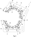
- a total of four locking fasteners 84 are provided on the carrier 70, two each for one of the segments 81, 82. In the closed state, the two segments 81, 82 are connected to one another by tension fasteners 83 '. When they are closed, the two segments 81 and 82 form the uniform magnetic ring 8.
- the magnetic ring 8 comprises a plurality (14 in the illustrated embodiments) of cylindrical sub-magnets 85 made of rare earth material. To hold them on the magnetic ring 8, suitable receptacles are provided on the magnetic ring 8. The cylindrical sub-magnets 85 are inserted into these and secured so that they cannot twist or fall out. The anti-twist protection is important because the individual sub-magnets 85 are inserted and held with a precisely defined angular orientation. The angular orientation serves for a specific orientation of the magnetic field generated by the respective sub-magnet 85 and is indicated by arrows in Figure 4 and 5 visualized (see also the explanation above for the meaning of the arrows). Figure 2 and 3b ).
- the angular orientation of the individual sub-magnets 85 is always different from the neighboring ones.
- the alignment is deliberately chosen so that the magnetic field is concentrated on the interior 80 (the exterior of the magnetic ring 8 is essentially field-free), and so an essentially homogeneous, directed static magnetic field is created in the interior 80 (cf. Figure 2 and the explanation above).
- the static magnetic field 88 generated in this way can be rotated, with a permanent magnet located in the interior 80 under the effect of the magnetic field rotating correspondingly synchronously.
- a permanent magnet is used as a drive element for the implant component, as will be explained later.
- a second embodiment for a drive unit 7 ' is in the Figures 6 to 11 shown. It differs in terms of its shape, but is functionally essentially similar to the first embodiment described above. For the same or similar parts are the same Reference numbers are used, with reference being made to the above explanation to avoid unnecessary repetitions, which should be applied accordingly.
- the second embodiment of the drive unit 7 ' has a housing 71 surrounding the magnetic ring instead of the carrier 70.
- a coupling opening 76 is provided in the housing 71 for possible flange-mounting of a drive motor.
- a drive motor (not shown) can be arranged here, which acts on the magnetic ring 8 and causes it to rotate. It should be noted that such a motor drive can also be provided in the first embodiment.
- the housing 71 is preferably made of soft magnetic material, for example highly permeable iron, nickel and/or cobalt alloys, in order to shield the outside space from the magnetic (residual) field of the magnetic ring 8.
- soft magnetic material for example highly permeable iron, nickel and/or cobalt alloys, in order to shield the outside space from the magnetic (residual) field of the magnetic ring 8.
- Low-alloy structural and free-cutting steels or electrical sheets are particularly useful.
- the housing 71 is designed to be shielding in the area of the lateral surface of the magnetic ring 8.
- the housing 71 is expediently dimensioned so that there is a distance of in the area of the shielding (e.g. lateral surface).
- the magnetic ring 8 which is at least as large as the diameter/height of the individual sub-magnets 85, preferably a multiple of this. This means that a good shielding effect can be achieved even with relatively small material thicknesses (typically 0.5 mm or less) and therefore little weight.
- the housing 71 would have to be designed with a fairly large depth in order to achieve the above-mentioned distance of the front housing wall of at least the diameter/height of the individual sub-magnets 85, or
- the material thickness of the front housing wall would have to be chosen to be considerably higher than in the area of the lateral surface, usually more than twice or even three times as thick (ie typically greater than 1 mm).
- the housing 71 is further provided with a directional receptacle for an extremity, for example a leg. However, it is not the extremity provided with the implant component 1 that is to be included here, but rather its contralateral counterpart, i.e. the other leg.
- the housing 71 is as in Figure 6 shown as an example, in the area of its base 6 'is provided with a recess which is essentially V-shaped in cross section and which forms a receptacle 61.
- the receptacle 61, 62 is expediently shaped so that it only accommodates the extremity in a defined position. If the lower leg or thigh of the other leg is placed in the receptacle 61, 62, the drive unit 7 ' So to speak, automatically correctly aligned for the adjustment of the implant component 1 to be adjusted (the same applies to other extremities, such as arms). This simplifies the correct use or positioning of the drive unit 7 'according to the invention for the user. It should be noted that the receptacles 61, 62 can also be designed as individually adapted shapes.
- the magnet ring 8 is provided with a large number of sub-magnets 85, which are shown in the partial sectional view in Figure 7 are shown.
- the magnetic ring 8 is divided into two segments 81, 82, which can be opened together with the upper half of the housing 71 (see Figures 8 and 9 ).
- a hinge 74 is provided on one side for this purpose.
- Figure 9 shows the second embodiment with the housing 71 completely opened. You can clearly see the respective ends of the segments 81, 82 on the separating surfaces, which are in the folded state (see Figure 7 ) lie in the parting plane 83.
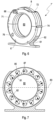
- guide elements 77 are provided. They are designed like a pawl and are arranged at the two ends of the guide rail 79 in the area of the parting plane 83 on the segments 81, 82 (see Fig. Fig. 12 and 13 ). They are part of a spring locking mechanism that holds the segments 81, 82 together. This results in effective guidance and securing for the magnetic ring 8 in the closed state, namely by means of the guide rollers 89 guided on the guide rail 79 and the guide elements 77 at the ends of the guide rail 79.
- a locking bolt 84 ' is provided, which can be inserted into corresponding receiving openings in the upper area of the housing 71 and in the upper segment 81 of the magnetic ring 8 (see. Fig. 12 a, b ).
- the position in which the magnetic ring 8 must be in order to insert the locking bolt 84 ' is the one in which the parting plane 83 between the segments 81, 82 is aligned with the hinge 74 of the housing 71 - opening is only possible in this basic position.
- the Correct position of the magnetic ring 8 in this basic position is indicated by a reference mark 74 ' arranged in the area of the housing opening 72, one half of which is attached to the housing 71 and the other half to the magnetic ring 8 (e.g. as a double arrow marking) - both are one above the other reaches the basic position.
- the receiving openings in the housing 71 and segment 81 of the magnetic ring 8 are aligned, and the locking pin 84 'can be inserted.
- the locking bolt 84' secures the upper segment 81 of the magnetic ring 8 against unwanted movement even when it is unfolded or in the unfolded state.
- a third embodiment for a drive unit 7" is shown in Fig. 13a, b and 14 shown. It is based on the second embodiment, but in contrast to this has a differently designed housing 71. It has an outer protective cover 72 'in the upper area, which is hingedly mounted on the hinge 74 and, when open, exposes the upper area of the magnetic ring 8. In the area of the hinge 74, an arm 71" is provided on the housing 71. On the one hand, it carries the handle 75' for transporting the drive unit 7" and, on the other hand, in this way forms a stop for the protective cover 72' in order to limit the opening to reach.
- the boom 71" is also shaped in such a way that its side contour offers a receptacle 61 for the contralateral extremity (the other leg). Otherwise, this is correct Functionality corresponds to that of the recording 61 in the second embodiment, so that reference is made to avoid repetitions. This also applies accordingly to the other components of the third embodiment, which have the same or corresponding reference numbers as the corresponding components of the second embodiment.
- the third embodiment also has a counterpart to the outer protective cover 72 '.
- An inner protective cover 71 ' is provided on the inside of the magnetic ring 8, which separates the interior 80 from the magnetic ring 8. It not only functions as a mechanical cover, but also serves to shield the surrounding area, especially neighboring areas of the limb to be picked up (particularly leg 9), from unnecessary exposure to magnetic fields.
- the magnetic ring 8 is mounted on guide rollers 89 'fixed to the housing, on which the magnetic ring 8 rests in its lower region with its lateral surface.
- This enables a compact structure with a relatively low center of gravity.
- the risk of the drive unit 7" accidentally tipping over can be counteracted.
- the guide rollers 89' are designed with an enlarged diameter on their end faces, so that a collar is created and a side guide for the magnetic ring 8 is achieved. Additional guide rollers 89' can also be used. be provided in particular in the upper area of the housing.
- the housing 71 has double feet 6". They give the drive unit 7" a wider contact area and thus further increase safety against tipping over.
- the To avoid repetition please refer to the above description of the second embodiment.
- Magnetic shielding can be provided on the magnetic ring 8 or the surrounding housing 71 and its components 71 ', 72', preferably made of magnetically highly conductive (highly permeable) material, in particular soft magnetic (ferromagnetic) materials such as iron, nickel and cobalt alloys.
- An outer shield 67 can be provided at a relatively large distance, which is understood to be a multiple of the diameter or height of the submagnets 85. With such a spaced-apart shielding, material thicknesses of the shielding material of only a few tenths of a millimeter are sufficient and advantageous.
- a directly adjacent sheath shielding 68 is expediently provided.
- the distance between the shielding is approximately equal to the diameter or height of the submagnets 85, so that material thicknesses of at least half a millimeter, preferably up to one millimeter, are expedient.
- Such sheath shielding can also be useful on the inside, for example on the inner protective cover 71 'of the third embodiment to protect surrounding areas of the affected leg 9.
- shielding can also be provided on the end faces of the magnetic wheel, as near-field shielding 69.
- the distance is typically smaller than the diameter or height of the submagnets 85, so that there is a strong magnetic control of the soft iron. Required are therefore quite large material thicknesses of at least one, usually several millimeters.
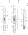
- FIG Fig. 17 to 19 An exemplary embodiment of an implant component 1 is shown in FIG Fig. 17 to 19 shown.
- Figure 17 shows a partial section through the implant component 1 with its adjustment device 2.
- the implant component 1 is shaped like a shaft in the exemplary embodiment shown and thus forms part of a prosthesis shaft, in particular for a modular prosthesis system.
- a coupling element to adjacent prosthesis modules of a preferably standardized prosthesis system, for example a further shaft or a connection to a joint component.
- the implant component 1 points at its in Fig. 17 at the end shown on the right a male cone 11 as a coupling element and at its end shown on the left in the illustration a coupling element designed as a female cone 12 for connecting further prosthesis modules (not shown); It goes without saying that other types of connection than cone connectors can also be provided.
- the actual shaft body between the coupling elements 11, 12 is designed with an outer tube 21 and an inner tube 22 which is guided in a longitudinally displaceable manner. They are part of an adjusting device 2 and work together telescopically in order to enable the setting of different lengths for the implant component 1.
- the outer tube 21 and the inner tube 22 are connected to one another via two sliding guides, one of which is arranged at the free end of the inner tube 22 and movable in the outer tube 21, while the other sliding guide 29 is fixed at the end of the outer tube 21 in Be rich of the transition to the inner tube 22 is arranged.
- a guide groove is arranged on the inner wall of the outer tube 21 in order to avoid mutual rotation of the inner tube 22 relative to the outer tube 21.
- the adjusting device 2 for adjusting the length of the implant component 1 further comprises a drive element 3, which has a permanent magnet arranged such that it can rotate about a central axis of the inner tube. It is arranged with such an orientation that its polarization direction (direction from the north pole to the south pole) is orthogonal to the central axis.
- a sub-magnet 85, as described above, is also expediently used for this purpose.
- Downstream of the drive element 3 is a gear 4 as a reduction gear. In the exemplary embodiment shown, it is designed as a two-stage planetary gear that has a reduction of approximately 1 to 20.
- the gear 4 acts on a spindle drive 5, which converts a rotary movement of the gear 4 into a linear movement for length adjustment.
- a bending rod 35 is provided for torque transmission between gear 4 and spindle drive 5.
- the gear 4 acts on a driven end 34 of the bending rod 35, which is arranged coaxially to the central axis 27 of the inner tube 22.
- the bending rod 35 further has a collar 36, which is arranged in the area of the sealing rings 24, and then has an elongated constricted shaft region 32, which ends at a coupling piece 37 at the free end of the bending rod 35.
- the elongated constricted one Shaft area 32 is inserted into a central bore 51 of the drive spindle 50 that is open on one side, the coupling piece 37 being connected to the drive spindle 50 at the bottom of the central bore 51.
- the drive spindle 50 which is set in rotation by the bending rod 35, rotates about a central axis 26 of the outer tube 21 and thus causes a longitudinal movement of an adjusting slide 52 arranged on the drive spindle 50, which is firmly connected to the inner tube 22.
- a rotation of the drive magnet 3 - via the reduction gear 4 and the spindle drive 5 - causes a longitudinal adjustment of the implant component 1.
- the remedy here is the bending rod 35, which can absorb the alignment error thanks to its bending (symbolized by the arrow representation in Fig. 19 ). It enables the compensation of misalignments in the range of up to +/- 5 degrees, preferably up to +/- 2 degrees. He thus increases the tolerance of the drive train to bending stress and thus increases the load capacity and reliability of the adjusting device 2 of the implant component 1.
- the implant component 1 is adjusted with its adjustment device 2 by placing the extremity (leg 9) with the implant component 1 in the interior 80 of the drive unit 7, 7 'so that the adjustment device 2 with its drive magnet 3 lies in the plane of the magnetic ring 8 .
- the magnetic field 88 which rotates synchronously with the magnetic ring 8 acts on the drive magnet 3, which is then also rotated correspondingly synchronously.
- the static magnetic field which, unlike a typical electromagnetically generated field (in particular an electric motor winding), is not modulated in terms of its strength but rather has a constant strength, slip between drive magnet 3 and magnetic ring 8 is reliably avoided.
- the angular position as well as the number of revolutions of the magnetic ring 8 is therefore the same as that of the drive magnet 3. A precise length adjustment can thus be carried out in a simple manner.
- the number of revolutions made for adjustment (and thus the adjustment distance achieved) is displayed on the counter 66 for the user.
Landscapes
- Health & Medical Sciences (AREA)
- Orthopedic Medicine & Surgery (AREA)
- Life Sciences & Earth Sciences (AREA)
- Surgery (AREA)
- Engineering & Computer Science (AREA)
- Animal Behavior & Ethology (AREA)
- Veterinary Medicine (AREA)
- Public Health (AREA)
- Biomedical Technology (AREA)
- Heart & Thoracic Surgery (AREA)
- General Health & Medical Sciences (AREA)
- Molecular Biology (AREA)
- Medical Informatics (AREA)
- Nuclear Medicine, Radiotherapy & Molecular Imaging (AREA)
- Neurology (AREA)
- Cardiology (AREA)
- Oral & Maxillofacial Surgery (AREA)
- Transplantation (AREA)
- Vascular Medicine (AREA)
- Robotics (AREA)
- Prostheses (AREA)
- Surgical Instruments (AREA)
- External Artificial Organs (AREA)
Applications Claiming Priority (3)
| Application Number | Priority Date | Filing Date | Title |
|---|---|---|---|
| EP20159426 | 2020-02-25 | ||
| PCT/EP2021/054500 WO2021170612A2 (fr) | 2020-02-25 | 2021-02-24 | Système d'implant réglable en longueur de manière extracorporelle, et composant d'implant réglable en longueur |
| EP21706310.6A EP4110208B1 (fr) | 2020-02-25 | 2021-02-24 | Système d'implant à réglage en longueur extracorporel ainsi que composant d'implant réglable en longueur |
Related Parent Applications (2)
| Application Number | Title | Priority Date | Filing Date |
|---|---|---|---|
| EP21706310.6A Division EP4110208B1 (fr) | 2020-02-25 | 2021-02-24 | Système d'implant à réglage en longueur extracorporel ainsi que composant d'implant réglable en longueur |
| EP21706310.6A Division-Into EP4110208B1 (fr) | 2020-02-25 | 2021-02-24 | Système d'implant à réglage en longueur extracorporel ainsi que composant d'implant réglable en longueur |
Publications (2)
| Publication Number | Publication Date |
|---|---|
| EP4279033A2 true EP4279033A2 (fr) | 2023-11-22 |
| EP4279033A3 EP4279033A3 (fr) | 2024-01-03 |
Family
ID=69846207
Family Applications (2)
| Application Number | Title | Priority Date | Filing Date |
|---|---|---|---|
| EP23201401.9A Pending EP4279033A3 (fr) | 2020-02-25 | 2021-02-24 | Unité d'entraînement extracorporelle pour un système d'implant à longueur extra-corporel réglable et système d'implant à longueur réglable |
| EP21706310.6A Active EP4110208B1 (fr) | 2020-02-25 | 2021-02-24 | Système d'implant à réglage en longueur extracorporel ainsi que composant d'implant réglable en longueur |
Family Applications After (1)
| Application Number | Title | Priority Date | Filing Date |
|---|---|---|---|
| EP21706310.6A Active EP4110208B1 (fr) | 2020-02-25 | 2021-02-24 | Système d'implant à réglage en longueur extracorporel ainsi que composant d'implant réglable en longueur |
Country Status (8)
| Country | Link |
|---|---|
| US (1) | US20230109975A1 (fr) |
| EP (2) | EP4279033A3 (fr) |
| JP (1) | JP2023515370A (fr) |
| KR (1) | KR20220146511A (fr) |
| CN (1) | CN115135260A (fr) |
| AU (1) | AU2021225337A1 (fr) |
| ES (1) | ES3041325T3 (fr) |
| WO (1) | WO2021170612A2 (fr) |
Families Citing this family (4)
| Publication number | Priority date | Publication date | Assignee | Title |
|---|---|---|---|---|
| US20240260997A1 (en) * | 2008-11-10 | 2024-08-08 | Nuvasive Specialized Orthopedics, Inc. | External adjustment device for distraction device |
| KR102622400B1 (ko) * | 2021-10-01 | 2024-01-09 | 주식회사 엔가든 | 정형외과 임플란트 수술용 입체정위기 |
| CN119033510B (zh) * | 2024-10-31 | 2025-01-28 | 北京爱康宜诚医疗器材有限公司 | 关节假体 |
| CN120304932B (zh) * | 2025-06-17 | 2025-09-16 | 山东君泰安德医疗科技股份有限公司 | 一种磁力牵引式骨延长装置 |
Family Cites Families (6)
| Publication number | Priority date | Publication date | Assignee | Title |
|---|---|---|---|---|
| GB0009107D0 (en) * | 2000-04-13 | 2000-05-31 | Univ London | Surgical distraction device |
| US7481841B2 (en) * | 2004-06-30 | 2009-01-27 | Depuy Products, Inc. | Adjustable orthopaedic prosthesis and associated method |
| US7753915B1 (en) * | 2007-06-14 | 2010-07-13 | August Eksler | Bi-directional bone length adjustment system |
| US8777947B2 (en) * | 2010-03-19 | 2014-07-15 | Smith & Nephew, Inc. | Telescoping IM nail and actuating mechanism |
| WO2012112396A2 (fr) * | 2011-02-14 | 2012-08-23 | Ellipse Technologies, Inc. | Dispositif et méthode de traitement d'os fracturés |
| CN102895048B (zh) * | 2012-09-14 | 2016-12-21 | SAMBU Medical株式会社 | 非手术方法延长长度的人体用人造骨骼 |
-
2021
- 2021-02-24 WO PCT/EP2021/054500 patent/WO2021170612A2/fr not_active Ceased
- 2021-02-24 KR KR1020227031499A patent/KR20220146511A/ko not_active Withdrawn
- 2021-02-24 US US17/904,710 patent/US20230109975A1/en active Pending
- 2021-02-24 AU AU2021225337A patent/AU2021225337A1/en not_active Abandoned
- 2021-02-24 JP JP2022548675A patent/JP2023515370A/ja active Pending
- 2021-02-24 CN CN202180016430.0A patent/CN115135260A/zh active Pending
- 2021-02-24 EP EP23201401.9A patent/EP4279033A3/fr active Pending
- 2021-02-24 ES ES21706310T patent/ES3041325T3/es active Active
- 2021-02-24 EP EP21706310.6A patent/EP4110208B1/fr active Active
Also Published As
| Publication number | Publication date |
|---|---|
| JP2023515370A (ja) | 2023-04-13 |
| KR20220146511A (ko) | 2022-11-01 |
| US20230109975A1 (en) | 2023-04-13 |
| ES3041325T3 (en) | 2025-11-11 |
| EP4279033A3 (fr) | 2024-01-03 |
| CN115135260A (zh) | 2022-09-30 |
| WO2021170612A2 (fr) | 2021-09-02 |
| EP4110208B1 (fr) | 2025-07-23 |
| WO2021170612A3 (fr) | 2021-10-21 |
| AU2021225337A1 (en) | 2022-09-08 |
| EP4110208A2 (fr) | 2023-01-04 |
Similar Documents
| Publication | Publication Date | Title |
|---|---|---|
| EP4110208B1 (fr) | Système d'implant à réglage en longueur extracorporel ainsi que composant d'implant réglable en longueur | |
| DE69633302T2 (de) | Regelbare positionierungsanlage für knochen | |
| DE60215380T2 (de) | Medizinisches bilderzeugungssystem | |
| EP1033112B1 (fr) | Clou intramédullaire pour la distraction des os | |
| DE10065232C2 (de) | Implantat zum Einsetzen zwischen Wirbelkörper sowie Operationsinstrument zur Handhabung des Implantats | |
| DE3202521C2 (de) | Schwenkgelenkendoprothese | |
| DE112014001466T5 (de) | Flexibler Arm und Verfahren zu dessen Verwendung | |
| DE102018115435A1 (de) | Trokarhalterung | |
| EP1284690A1 (fr) | Instruments pour mettre en place une prothese cotyloidienne | |
| EP2394606A1 (fr) | Prothèse pour le remplacement partiel d'un os long | |
| DE69731774T2 (de) | Manipulierzange | |
| DE102013111683A1 (de) | Wirbelsäulenstabilisierungsystem, medizinisches Instrumentarium und medizinische Vorrichtung zum parallelen Ausrichten medizinischer Instrumente | |
| DE1179349B (de) | Fernbetaetigbares Handhabungsgeraet (Manipulator) | |
| EP0568676A1 (fr) | Endoprothese. | |
| DE202011000075U1 (de) | Halteeinrichtung zum Halten und Positionieren eines Retraktors für medizinische Anwendungen | |
| EP0170982A1 (fr) | Endoprothèse d'articulation, particulièrement prothèse d'articulation de la hanche | |
| DE3937594A1 (de) | Verfahren und vorrichtung zur extrahierung in einem koerperorgan eingewachsener elektrodenspiralen | |
| EP3058897A1 (fr) | Endoprothese pour arthrodese du genou | |
| EP2910221B1 (fr) | Dispositif de dégagement pour libérer un implant médical d'un cathéter ainsi que cathéter avec dispositif de dégagement | |
| DE3305597A1 (de) | Richtgeraet fuer knochenbrueche | |
| EP4057952A1 (fr) | Dispositif orthopédique | |
| EP0533700A1 (fr) | Dispositif pour l'extraction de spirales d'electrodes introduites dans un organe du corps humain. | |
| DE3935488A1 (de) | Kniegelenk-endoprothese | |
| DE69111931T2 (de) | Verbesserungen an einer externen befestigungsvorrichtung. | |
| DE102009060557B4 (de) | Prothetisches Hilfsmittel |
Legal Events
| Date | Code | Title | Description |
|---|---|---|---|
| PUAI | Public reference made under article 153(3) epc to a published international application that has entered the european phase |
Free format text: ORIGINAL CODE: 0009012 |
|
| STAA | Information on the status of an ep patent application or granted ep patent |
Free format text: STATUS: REQUEST FOR EXAMINATION WAS MADE |
|
| 17P | Request for examination filed |
Effective date: 20231003 |
|
| AC | Divisional application: reference to earlier application |
Ref document number: 4110208 Country of ref document: EP Kind code of ref document: P |
|
| AK | Designated contracting states |
Kind code of ref document: A2 Designated state(s): AL AT BE BG CH CY CZ DE DK EE ES FI FR GB GR HR HU IE IS IT LI LT LU LV MC MK MT NL NO PL PT RO RS SE SI SK SM TR |
|
| REG | Reference to a national code |
Ref country code: DE Ref legal event code: R079 Free format text: PREVIOUS MAIN CLASS: A61F0002380000 Ipc: A61B0017720000 |
|
| PUAL | Search report despatched |
Free format text: ORIGINAL CODE: 0009013 |
|
| AK | Designated contracting states |
Kind code of ref document: A3 Designated state(s): AL AT BE BG CH CY CZ DE DK EE ES FI FR GB GR HR HU IE IS IT LI LT LU LV MC MK MT NL NO PL PT RO RS SE SI SK SM TR |
|
| RIC1 | Information provided on ipc code assigned before grant |
Ipc: A61F 2/28 20060101ALI20231124BHEP Ipc: A61B 17/72 20060101AFI20231124BHEP |
|
| GRAP | Despatch of communication of intention to grant a patent |
Free format text: ORIGINAL CODE: EPIDOSNIGR1 |
|
| STAA | Information on the status of an ep patent application or granted ep patent |
Free format text: STATUS: GRANT OF PATENT IS INTENDED |
|
| RIC1 | Information provided on ipc code assigned before grant |
Ipc: A61B 17/72 20060101AFI20260209BHEP Ipc: A61F 2/28 20060101ALI20260209BHEP |
|
| INTG | Intention to grant announced |
Effective date: 20260303 |