EP4279347B1 - Appareil de connexion d'air - Google Patents
Appareil de connexion d'air Download PDFInfo
- Publication number
- EP4279347B1 EP4279347B1 EP22180302.6A EP22180302A EP4279347B1 EP 4279347 B1 EP4279347 B1 EP 4279347B1 EP 22180302 A EP22180302 A EP 22180302A EP 4279347 B1 EP4279347 B1 EP 4279347B1
- Authority
- EP
- European Patent Office
- Prior art keywords
- air
- connection
- chamber
- spring brake
- brake chamber
- Prior art date
- Legal status (The legal status is an assumption and is not a legal conclusion. Google has not performed a legal analysis and makes no representation as to the accuracy of the status listed.)
- Active
Links
Images



Classifications
-
- B—PERFORMING OPERATIONS; TRANSPORTING
- B60—VEHICLES IN GENERAL
- B60T—VEHICLE BRAKE CONTROL SYSTEMS OR PARTS THEREOF; BRAKE CONTROL SYSTEMS OR PARTS THEREOF, IN GENERAL; ARRANGEMENT OF BRAKING ELEMENTS ON VEHICLES IN GENERAL; PORTABLE DEVICES FOR PREVENTING UNWANTED MOVEMENT OF VEHICLES; VEHICLE MODIFICATIONS TO FACILITATE COOLING OF BRAKES
- B60T17/00—Component parts, details, or accessories of power brake systems not covered by groups B60T8/00, B60T13/00 or B60T15/00, or presenting other characteristic features
- B60T17/08—Brake cylinders other than ultimate actuators
- B60T17/088—Mounting arrangements
-
- B—PERFORMING OPERATIONS; TRANSPORTING
- B60—VEHICLES IN GENERAL
- B60T—VEHICLE BRAKE CONTROL SYSTEMS OR PARTS THEREOF; BRAKE CONTROL SYSTEMS OR PARTS THEREOF, IN GENERAL; ARRANGEMENT OF BRAKING ELEMENTS ON VEHICLES IN GENERAL; PORTABLE DEVICES FOR PREVENTING UNWANTED MOVEMENT OF VEHICLES; VEHICLE MODIFICATIONS TO FACILITATE COOLING OF BRAKES
- B60T17/00—Component parts, details, or accessories of power brake systems not covered by groups B60T8/00, B60T13/00 or B60T15/00, or presenting other characteristic features
- B60T17/04—Arrangements of piping, valves in the piping, e.g. cut-off valves, couplings or air hoses
- B60T17/043—Brake line couplings, air hoses and stopcocks
Definitions
- the invention relates to a connection apparatus to provide air connection for the spring brake chamber and to a spring brake chamber comprising said connection apparatus.
- the spring brake chambers are frequently used in heavy commercial vehicles such as trucks, tow trucks, trailers, and buses.
- the spring brake chamber is a system that directly drives the braking mechanism and is a pneumatic brake solution.
- the said system includes two rooms, the service and the emergency room. In the first of these rooms, there is a service diaphragm, the brake actuating shaft extending out of the room and connected to the diaphragm, and a spring placed on the actuating shaft.
- the second room there is pressure air under normal conditions.
- the second room also contains an actuating arm extending into the primary room, a diaphragm connected to the actuating arm, and a secondary spring stronger than the spring in the first room.
- the air in the secondary room is evacuated and the secondary spring pushes an actuating arm extending into the primary room with high force, and this actuating arm starts the braking by pushing the actuating arm in the first room.
- US4105226A discloses a coupling ring for use in snap-in fittings of the type including male and female connector elements, the male connector element including a ring-retaining channel and the female connector element including locking grooves.
- the document with publication number DE20100803U1 discloses a spring brake chamber.
- Said spring brake chamber is arranged according to the foregoing basic working principle given above.
- the air connection of the spring brake chamber is provided by a connection element connected to the air inlets on the brake chamber.
- Said connection element is connected to the air inlet with a screw placed from the end part.
- Screwed assembly is performed by applying torque.
- This torque application may cause damage to the screw threads and also damage the o-rings placed to seal the air inlet.
- screwed systems can get loose with axial and radial vibrations occurring during the operation of the vehicle. In such a case, the spring chamber will lose its function and cause safety problems.
- the main object of the present invention is to provide the structure of an air connection apparatus that can be easily connected to the spring brake chamber without the need for torque application, also which will not be affected by the vibrations occurring during the operation of the vehicle and cannot be disassembled by the user.
- the present air connection apparatus comprises at least one airline, one end of which is arranged to be an air connection head to be connected to an air source and another end of which is arranged to be a chamber connection head to be connected to the spring brake chamber and is angled in respect to the air connection head, which is provided at an angle to the air connection head, and which includes at least one an air channel extending from the chamber connection head to the air connection head to allow air passage, a primary channel formed in the outer diameter of said chamber connection head to allow a circlip to be inserted.
- the air connection apparatus unlike the torque applications of the air connection apparatus, it is allowed to insert a circlip in the primary channel and therefore, it is allowed to mount the air connection apparatus by pushing it axially into the air inlet of the spring brake chamber.
- the circlip provides a click-on assembly between the spring brake chamber and the air connection apparatus, and this click-on system also prevents users from removing the air connection apparatus by showing a locking function.
- a preferred embodiment of the invention includes a sealing channel formed in the outer diameter of the said chamber connection head to allow a sealing element to be placed, and accordingly, the sealing of the spring brake chamber is increased.
- a preferred embodiment of the invention includes two air lines. Accordingly, the air connection apparatus can allow air to enter both rooms of the spring brake chamber, and both connections can be provided with a single assembly move.
- a preferred embodiment of the invention includes at least one connection hole on the said connection support.
- the connection hole allows the stud connection elements to connect the air connection apparatus to the spring brake chamber.
- a preferred embodiment of the invention includes a release bolt slot on the said connection support.
- extra space is provided for the housing of the release bolt with slots for carrying the release bolt thereon.
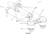
- connection apparatus (1) to provide air connection for the spring brake chamber (12) and to a spring brake chamber (12) comprising said connection apparatus (1).
- the air connection element (1) comprises at least one, preferably two air lines (5).
- Said air line (5) is preferably provided in the form of a cylindrical tube.
- One end of the said air line (5) is connected to the spring brake chamber (12) with the chamber connection head (2) and its other end is connected to an air source (not shown in the figures) with the air connection head (2a).
- the said air line (5) is arranged as an air channel (7) to allow air passage to the inner part.
- the air channel (7) extends from the air connection head (2a) towards the chamber connection head (2).
- Said chamber connection head (2) and air connection head (2a) are provided at an angle, preferably perpendicular to each other.
- An approximate "L" shape is provided.
- the air channel (7) is arranged such that the part passing through the chamber connection head (2) is at an angle to the remaining part in accordance with this geometry.
- screw threads (4) in the inner diameter of the head and its outer diameter can be formed as a nut head (3). If required, both or only one of the nut head (3) and screw threads (4) can be used.
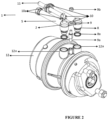
- the chamber connection head (2) of the said air connection apparatus (1) is inserted into the air inlet (12a) of the spring brake chamber (12).
- the spring brake chamber (12) includes two air inlets (12a), and as will be explained later, each air inlet (12a) is provided in connection with a room of the spring brake chamber (12).
- the air inlets (12a) are structures extending vertically from the surface of the spring brake chamber (12). Since the chamber connection head (2) is angled, preferably perpendicular to the remaining part of the air line (5), it can be fixed by being pushed in the axial direction to the air inlet (12a).
- a primary channel (6) is arranged in the outer diameter of the end part of the chamber connection head (2).
- the primary channel (6) has a structure deepening in the radial direction on the surface of the chamber connection head (2) and it is configured to accommodate a circlip (6a).
- Said circlip (6a) can be either found ready on the air connection apparatus (1) or it can be inserted during assembly.
- the circlip (6a) is inserted into the primary channel (6) and the chamber connection head (2) is pushed into the air inlet (12a)
- the circlip (6a) fastens the air connection apparatus (1) to the spring brake chamber (12) by being compressed between the primary channel (6) and the inner surface of the air inlet (12a).
- the user cannot move the chamber connection head (2) out of the air inlet (12a) due to the positioning of the circlip (6a).
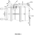
- a secondary channel (12b) can be formed on the inner surface of the air inlet (12a) as well as the primary channel (6).
- said secondary channel (12b) is positioned to be opposite the primary channel (6).
- the outer diameter of the circlip (6a) fits inside the secondary channel (12b), and the radial movement of the circlip (6a) in the radial direction is prevented by the walls of the secondary channel (12b), and accordingly, a more stable structure with stronger locking feature has been provided.
- a sealing channel (8) is arranged in the outer diameter of the end part of the chamber connection head (2).
- the sealing channel (8) is located on the primary channel (6) in the radial direction, that is, in the part away from the spring brake chamber (12).
- the sealing channel (8) has a structure deepening in the radial direction on the surface of the chamber connection head (2) and it is configured to accommodate a sealing element (8a).
- Said sealing element (8a) can be either found ready on the air connection apparatus (1) or it can be inserted during assembly.
- the sealing element (8a) is inserted into the sealing channel (8) and the chamber connection head (2) is pushed into the air inlet (12a)
- the sealing element (8a) is compressed between the sealing channel (8) and the inner surface of the air inlet (12a) and prevents possible air leakages that may occur at the air inlet (12a).
- the air connection apparatus (1) may comprise two air lines (5).
- these two air lines (5) are conjugated with each other.
- connection support (10) There may be a connection hole (9) and/or a release bolt slot (10a) on the said connection support (10).
- connection hole (9) allows the air connection apparatus (1) to connect to the spring brake chamber (12) via a stud connection element (9a) and the second connection element (9b).
- the stud connection element (9a) and the second connection element (9b) may be selected as a stud screw and nut, respectively. One end of the stud screw is inserted into the slot on the spring brake chamber (12), and then the other end is passed through the connection hole (9) and then the nut is mounted on this end.
- the release bolt slot (10a) allows the release bolt (11) to be placed directly in the air connection apparatus (1).
- the release bolt (11) is in the form of a longitudinal shaft and may contain threads extending in the radial direction at its end part.
- the release bolt (11) is positioned parallel to the air line (5).
- the release bolt slot (10a) includes an opening perpendicular to the connection support (10) for the said longitudinal part to pass through, and the release bolt (11) is passed through here.
- another opening can be arranged on the surface of another connection support (10) as a secondary release bolt slot (10a).
- the radial thread of the release bolt (11) previously described fits into this secondary opening.
- connection apparatus (1) is connected to a spring brake chamber (12).
- the inner body part of the spring brake chamber (12) is divided into two parts with an adapter plate (A), the primary room (C1) and the secondary room (C2).
- One of the two said air inlets (12a) is connected to the primary room (C1) and the other to the secondary room (C2).
- a diaphragm (D) is located in the primary room (C1). Said diaphragm (D) can move with the air from the air inlet (12a).
- a primary spring (S1) is placed on the primary actuating arm (T1).
- a secondary actuating arm (T2) between this diaphragm (D) and adapter plate (A).
- One end of the said secondary actuating arm (T2) is connected to the diaphragm (D), and the other end extends to the primary room (C1) by passing through the adapter plate (A).
- a secondary spring (S2) is positioned from the other side of the diaphragm (D).
- the secondary spring (S2) is chosen to apply more force than the primary spring (S1).
- a primary spring (S1) can also be located between the adapter plate (A) and the diaphragm (D) in the second room (C2).
- the secondary room (C2) is normally filled with air and this air compresses the secondary spring (S2) by pushing the diaphragm (D) and prevents the secondary actuating arm (T2) from advancing through the primary room.
- the air in the secondary room (C2) is evacuated and the diaphragm (D) cannot hold the secondary spring (S2).
- the secondary spring (S2) moves the secondary actuating arm (T2) by pushing the diaphragm (D), and accordingly, the secondary actuating arm (T2) actuates the brake mechanism by pushing the diaphragm (D) in the primary room (C1) and thus the primary actuating arm (T1).
Landscapes
- Engineering & Computer Science (AREA)
- Transportation (AREA)
- Mechanical Engineering (AREA)
- Braking Arrangements (AREA)
- Valves And Accessory Devices For Braking Systems (AREA)
Claims (11)
- Chambre de frein à ressort (12) ayant deux appareils de connexion d'air (1) pour connecter les sources d'air à une chambre d'air à ressort (12) par des entrées d'air (12a) de la chambre de frein à ressort (12), caractérisée par▪ L'appareil de connexion d'air (1) comprend au moins une conduite d'air (5), dont une extrémité est agencée pour être une tête de connexion d'air (2.a) à connecter à une source d'air et dont l'autre extrémité est agencée pour être une tête de connexion de chambre (2) à connecter à la chambre de frein à ressort (12) et qui est inclinée par rapport à la tête de connexion d'air (2. a), et qui comprend au moins un canal d'air (7) s'étendant de la tête de connexion de la chambre (2) à la tête de connexion de l'air (2.a) pour permettre le passage de l'air et un canal primaire (6) formé dans le diamètre extérieur de ladite tête de connexion de la chambre (2) pour permettre à un circlip (6a) d'être inséré,▪ au moins un support de connexion (10) connectant deux conduites d'air (5) et au moins un trou de connexion (9) sur le support de connexion (10) pour permettre à l'appareil de connexion d'air (1) de se connecter à la chambre de frein à ressort (12) par un élément de connexion à goujon (9a) et le deuxième élément de connexion (9b),▪ un canal secondaire (12b) formé sur la surface intérieure de l'entrée d'air (12a) dans lequel ledit canal secondaire (12b) est positionné pour être opposé au canal primaire (6), lorsque la tête de connexion de la chambre (2) est complètement insérée dans l'entrée d'air (12a).
- Chambre de frein à ressort (12) selon la revendication 1, caractérisée en ce que la tête de connexion de la chambre (2) est perpendiculaire à la tête de connexion de l'air (2.a).
- Chambre de frein à ressort (12) selon la revendication 1, caractérisée en ce qu'elle comprend un canal d'étanchéité (8) formé dans le diamètre extérieur de ladite tête de connexion de chambre (2) pour permettre à un élément d'étanchéité (8a) d'être inséré.
- Chambre de frein à ressort (12) selon la revendication 3, caractérisée en ce qu'elle comprend un élément d'étanchéité (8a) situé dans le canal d'étanchéité (8).
- Chambre de frein à ressort (12) selon la revendication 4, caractérisée en ce que l'élément d'étanchéité (8a) est un joint torique.
- Chambre de frein à ressort (12) selon la revendication 1, caractérisée en ce qu'elle comprend un circlip (6a) situé dans le canal primaire (6).
- Chambre de frein à ressort (12) selon la revendication 1, caractérisée en ce qu'elle comprend au moins deux supports de connexion (10).
- Chambre de frein à ressort (12) selon la revendication 1 ou 7, caractérisée en ce qu'elle comprend une fente de boulon de déclenchement (10.a) sur le support de connexion (10).
- Chambre de frein à ressort (12) selon l'une quelconque des revendications 1, 7 ou 8, caractérisée en ce qu'elle comprend au moins trois supports de connexion (10).
- Chambre de frein à ressort (12) selon la revendication 9, caractérisée en ce qu'elle comprend deux supports de connexion (10) avec la fente du boulon de déclenchement (10.a) et un support de connexion avec le trou de connexion (9).
- Chambre de frein à ressort (12) selon l'une quelconque des revendications 1-3 ou 7-10, caractérisée en ce qu'elle est d'une seule pièce.
Applications Claiming Priority (1)
| Application Number | Priority Date | Filing Date | Title |
|---|---|---|---|
| TR202207995 | 2022-05-17 |
Publications (3)
| Publication Number | Publication Date |
|---|---|
| EP4279347A1 EP4279347A1 (fr) | 2023-11-22 |
| EP4279347B1 true EP4279347B1 (fr) | 2025-05-28 |
| EP4279347C0 EP4279347C0 (fr) | 2025-05-28 |
Family
ID=88405075
Family Applications (1)
| Application Number | Title | Priority Date | Filing Date |
|---|---|---|---|
| EP22180302.6A Active EP4279347B1 (fr) | 2022-05-17 | 2022-06-22 | Appareil de connexion d'air |
Country Status (2)
| Country | Link |
|---|---|
| EP (1) | EP4279347B1 (fr) |
| HU (1) | HUE071611T2 (fr) |
Families Citing this family (2)
| Publication number | Priority date | Publication date | Assignee | Title |
|---|---|---|---|---|
| EP4691866A1 (fr) * | 2024-08-09 | 2026-02-11 | ZF CV Systems Europe BV | Actionneur de frein à ressort comprenant un support de ligne de freinage |
| EP4691867A1 (fr) * | 2024-08-09 | 2026-02-11 | ZF CV Systems Europe BV | Actionneur de frein à ressort comprenant un support de ligne de freinage |
Family Cites Families (8)
| Publication number | Priority date | Publication date | Assignee | Title |
|---|---|---|---|---|
| US4105226A (en) * | 1976-06-01 | 1978-08-08 | Celanese Corporation | Snap-in fittings and coupling ring therefor |
| US4884829A (en) * | 1986-09-16 | 1989-12-05 | Johannes Schaefer Vorm. Stettiner Schraubenwerke Gmbh & Co. Kg | Plug-in connection for connecting tube and host lines in particular for use in tube-line systems of motor vehicles |
| US6378908B1 (en) * | 1999-12-08 | 2002-04-30 | Itt Manufacturing Enterprises, Inc. | High pressure quick connector |
| DE20100803U1 (de) | 2001-01-17 | 2001-03-08 | BPW Bergische Achsen KG, 51674 Wiehl | Druckluft-Bremszylinder für den Antrieb von Fahrzeugbremsen |
| EP2084445A1 (fr) * | 2006-11-10 | 2009-08-05 | Norgren Limited | Insert de coupleur à extrémité positive et coupleur |
| DE102013014449A1 (de) * | 2013-08-30 | 2015-03-05 | Knorr-Bremse Systeme für Nutzfahrzeuge GmbH | Druckluftbetätigter Bremszylinder mit abgedeckter Be- und Entlüftungsbohrung |
| ITUA20164698A1 (it) * | 2016-06-28 | 2017-12-28 | Tosi F Lli S R L | Insieme connettore |
| CN111561623A (zh) * | 2020-05-25 | 2020-08-21 | 长春亚大汽车零件制造有限公司 | 一种商用车气制动系统管路用快插接头锁止结构 |
-
2022
- 2022-06-22 EP EP22180302.6A patent/EP4279347B1/fr active Active
- 2022-06-22 HU HUE22180302A patent/HUE071611T2/hu unknown
Also Published As
| Publication number | Publication date |
|---|---|
| HUE071611T2 (hu) | 2025-09-28 |
| EP4279347A1 (fr) | 2023-11-22 |
| EP4279347C0 (fr) | 2025-05-28 |
Similar Documents
| Publication | Publication Date | Title |
|---|---|---|
| EP4279347B1 (fr) | Appareil de connexion d'air | |
| KR100274652B1 (ko) | 차량 브레이크용 액츄에이터장치 | |
| US5161830A (en) | Pipe joint | |
| US5918913A (en) | Quick-connect coupling for articulating hose lines | |
| JPH1159391A (ja) | ブレーキアクチュエータ | |
| US4431215A (en) | Riser connector | |
| CA2984607C (fr) | Outil de sertissage axial | |
| CN114294357A (zh) | 带隔膜保持器的弹簧制动致动器 | |
| US5873296A (en) | Booster apparatus of vacuum type | |
| AU679010B2 (en) | Spring brake actuator and caging bolt therefor | |
| EP4015323A2 (fr) | Actionneur de frein à ressort destiné à être utilisé dans un véhicule utilitaire et véhicule utilitaire le comprenant | |
| JP7071352B2 (ja) | 軸のカシメ工具 | |
| GB2168758A (en) | Manual release means for a brake | |
| JP3256244B2 (ja) | 低減された容積置換及び先導されたスナップリングを有する高圧クイックコネクタ | |
| US6382078B1 (en) | Attachment structure for brake-equipped cylinder | |
| US8777333B2 (en) | Brake force generator for a motor vehicle brake system having a support device for a resetting spring | |
| KR970011480B1 (ko) | 신속 연결 및 분리 요우크 조립체 | |
| US5791232A (en) | Universal adapter pressure cap | |
| US11951958B2 (en) | Piston tube assembly for a spring brake actuator, and spring brake actuator | |
| EP4071015B1 (fr) | Actionneur de frein à ressort pneumatique | |
| US12090972B2 (en) | Spring brake actuator | |
| JPH03209087A (ja) | 管接続装置 | |
| JP7791888B2 (ja) | ブレーキ装置の操作装置用の軸方向力伝達器、および軸方向力伝達器を製造する方法 | |
| TR2022007995A2 (tr) | Bi̇r hava bağlanti aparati | |
| EP1419948A1 (fr) | Tirant et procédé d'assemblage d'un servomoteur |
Legal Events
| Date | Code | Title | Description |
|---|---|---|---|
| PUAI | Public reference made under article 153(3) epc to a published international application that has entered the european phase |
Free format text: ORIGINAL CODE: 0009012 |
|
| STAA | Information on the status of an ep patent application or granted ep patent |
Free format text: STATUS: THE APPLICATION HAS BEEN PUBLISHED |
|
| AK | Designated contracting states |
Kind code of ref document: A1 Designated state(s): AL AT BE BG CH CY CZ DE DK EE ES FI FR GB GR HR HU IE IS IT LI LT LU LV MC MK MT NL NO PL PT RO RS SE SI SK SM TR |
|
| STAA | Information on the status of an ep patent application or granted ep patent |
Free format text: STATUS: REQUEST FOR EXAMINATION WAS MADE |
|
| RBV | Designated contracting states (corrected) |
Designated state(s): AL AT BE BG CH CY CZ DE DK EE ES FI FR GB GR HR HU IE IS IT LI LT LU LV MC MK MT NL NO PL PT RO RS SE SI SK SM TR |
|
| 17P | Request for examination filed |
Effective date: 20240510 |
|
| GRAP | Despatch of communication of intention to grant a patent |
Free format text: ORIGINAL CODE: EPIDOSNIGR1 |
|
| STAA | Information on the status of an ep patent application or granted ep patent |
Free format text: STATUS: GRANT OF PATENT IS INTENDED |
|
| GRAS | Grant fee paid |
Free format text: ORIGINAL CODE: EPIDOSNIGR3 |
|
| INTG | Intention to grant announced |
Effective date: 20250324 |
|
| GRAA | (expected) grant |
Free format text: ORIGINAL CODE: 0009210 |
|
| STAA | Information on the status of an ep patent application or granted ep patent |
Free format text: STATUS: THE PATENT HAS BEEN GRANTED |
|
| AK | Designated contracting states |
Kind code of ref document: B1 Designated state(s): AL AT BE BG CH CY CZ DE DK EE ES FI FR GB GR HR HU IE IS IT LI LT LU LV MC MK MT NL NO PL PT RO RS SE SI SK SM TR |
|
| REG | Reference to a national code |
Ref country code: GB Ref legal event code: FG4D |
|
| REG | Reference to a national code |
Ref country code: CH Ref legal event code: EP |
|
| REG | Reference to a national code |
Ref country code: IE Ref legal event code: FG4D |
|
| U01 | Request for unitary effect filed |
Effective date: 20250602 |
|
| U07 | Unitary effect registered |
Designated state(s): AT BE BG DE DK EE FI FR IT LT LU LV MT NL PT RO SE SI Effective date: 20250611 |
|
| PGFP | Annual fee paid to national office [announced via postgrant information from national office to epo] |
Ref country code: HU Payment date: 20250604 Year of fee payment: 4 |
|
| REG | Reference to a national code |
Ref country code: HU Ref legal event code: AG4A Ref document number: E071611 Country of ref document: HU |
|
| PG25 | Lapsed in a contracting state [announced via postgrant information from national office to epo] |
Ref country code: ES Free format text: LAPSE BECAUSE OF FAILURE TO SUBMIT A TRANSLATION OF THE DESCRIPTION OR TO PAY THE FEE WITHIN THE PRESCRIBED TIME-LIMIT Effective date: 20250528 |
|
| PG25 | Lapsed in a contracting state [announced via postgrant information from national office to epo] |
Ref country code: GR Free format text: LAPSE BECAUSE OF FAILURE TO SUBMIT A TRANSLATION OF THE DESCRIPTION OR TO PAY THE FEE WITHIN THE PRESCRIBED TIME-LIMIT Effective date: 20250829 Ref country code: NO Free format text: LAPSE BECAUSE OF FAILURE TO SUBMIT A TRANSLATION OF THE DESCRIPTION OR TO PAY THE FEE WITHIN THE PRESCRIBED TIME-LIMIT Effective date: 20250828 |
|
| PG25 | Lapsed in a contracting state [announced via postgrant information from national office to epo] |
Ref country code: PL Free format text: LAPSE BECAUSE OF FAILURE TO SUBMIT A TRANSLATION OF THE DESCRIPTION OR TO PAY THE FEE WITHIN THE PRESCRIBED TIME-LIMIT Effective date: 20250528 |
|
| PG25 | Lapsed in a contracting state [announced via postgrant information from national office to epo] |
Ref country code: HR Free format text: LAPSE BECAUSE OF FAILURE TO SUBMIT A TRANSLATION OF THE DESCRIPTION OR TO PAY THE FEE WITHIN THE PRESCRIBED TIME-LIMIT Effective date: 20250528 |
|
| PG25 | Lapsed in a contracting state [announced via postgrant information from national office to epo] |
Ref country code: RS Free format text: LAPSE BECAUSE OF FAILURE TO SUBMIT A TRANSLATION OF THE DESCRIPTION OR TO PAY THE FEE WITHIN THE PRESCRIBED TIME-LIMIT Effective date: 20250828 |
|
| PG25 | Lapsed in a contracting state [announced via postgrant information from national office to epo] |
Ref country code: IS Free format text: LAPSE BECAUSE OF FAILURE TO SUBMIT A TRANSLATION OF THE DESCRIPTION OR TO PAY THE FEE WITHIN THE PRESCRIBED TIME-LIMIT Effective date: 20250928 |
|
| U21 | Renewal fee for the european patent with unitary effect paid with additional fee |
Year of fee payment: 4 Effective date: 20251031 |
|
| PG25 | Lapsed in a contracting state [announced via postgrant information from national office to epo] |
Ref country code: SM Free format text: LAPSE BECAUSE OF FAILURE TO SUBMIT A TRANSLATION OF THE DESCRIPTION OR TO PAY THE FEE WITHIN THE PRESCRIBED TIME-LIMIT Effective date: 20250528 |
|
| PG25 | Lapsed in a contracting state [announced via postgrant information from national office to epo] |
Ref country code: CZ Free format text: LAPSE BECAUSE OF FAILURE TO SUBMIT A TRANSLATION OF THE DESCRIPTION OR TO PAY THE FEE WITHIN THE PRESCRIBED TIME-LIMIT Effective date: 20250528 |
|
| PG25 | Lapsed in a contracting state [announced via postgrant information from national office to epo] |
Ref country code: SK Free format text: LAPSE BECAUSE OF FAILURE TO SUBMIT A TRANSLATION OF THE DESCRIPTION OR TO PAY THE FEE WITHIN THE PRESCRIBED TIME-LIMIT Effective date: 20250528 |
|
| REG | Reference to a national code |
Ref country code: CH Ref legal event code: H13 Free format text: ST27 STATUS EVENT CODE: U-0-0-H10-H13 (AS PROVIDED BY THE NATIONAL OFFICE) Effective date: 20260127 |
|
| PG25 | Lapsed in a contracting state [announced via postgrant information from national office to epo] |
Ref country code: MC Free format text: LAPSE BECAUSE OF FAILURE TO SUBMIT A TRANSLATION OF THE DESCRIPTION OR TO PAY THE FEE WITHIN THE PRESCRIBED TIME-LIMIT Effective date: 20250528 |
|
| PLBE | No opposition filed within time limit |
Free format text: ORIGINAL CODE: 0009261 |
|
| STAA | Information on the status of an ep patent application or granted ep patent |
Free format text: STATUS: NO OPPOSITION FILED WITHIN TIME LIMIT |
|
| REG | Reference to a national code |
Ref country code: CH Ref legal event code: L10 Free format text: ST27 STATUS EVENT CODE: U-0-0-L10-L00 (AS PROVIDED BY THE NATIONAL OFFICE) Effective date: 20260409 |
|
| PG25 | Lapsed in a contracting state [announced via postgrant information from national office to epo] |
Ref country code: IE Free format text: LAPSE BECAUSE OF NON-PAYMENT OF DUE FEES Effective date: 20250622 |
|
| PG25 | Lapsed in a contracting state [announced via postgrant information from national office to epo] |
Ref country code: CH Free format text: LAPSE BECAUSE OF NON-PAYMENT OF DUE FEES Effective date: 20250630 |