EP4279403A2 - Appareil de stérilisation ayant un dispositif d'émission de faisceau d'irradiation et machine d'emballage dotée d'un appareil de stérilisation - Google Patents
Appareil de stérilisation ayant un dispositif d'émission de faisceau d'irradiation et machine d'emballage dotée d'un appareil de stérilisation Download PDFInfo
- Publication number
- EP4279403A2 EP4279403A2 EP23168903.5A EP23168903A EP4279403A2 EP 4279403 A2 EP4279403 A2 EP 4279403A2 EP 23168903 A EP23168903 A EP 23168903A EP 4279403 A2 EP4279403 A2 EP 4279403A2
- Authority
- EP
- European Patent Office
- Prior art keywords
- window
- sterilization apparatus
- irradiation beam
- packaging material
- tube
- Prior art date
- Legal status (The legal status is an assumption and is not a legal conclusion. Google has not performed a legal analysis and makes no representation as to the accuracy of the status listed.)
- Pending
Links
Images



Classifications
-
- B—PERFORMING OPERATIONS; TRANSPORTING
- B65—CONVEYING; PACKING; STORING; HANDLING THIN OR FILAMENTARY MATERIAL
- B65B—MACHINES, APPARATUS OR DEVICES FOR, OR METHODS OF, PACKAGING ARTICLES OR MATERIALS; UNPACKING
- B65B55/00—Preserving, protecting or purifying packages or package contents in association with packaging
- B65B55/02—Sterilising, e.g. of complete packages
- B65B55/04—Sterilising wrappers or receptacles prior to, or during, packaging
- B65B55/08—Sterilising wrappers or receptacles prior to, or during, packaging by irradiation
-
- A—HUMAN NECESSITIES
- A61—MEDICAL OR VETERINARY SCIENCE; HYGIENE
- A61L—METHODS OR APPARATUS FOR STERILISING MATERIALS OR OBJECTS IN GENERAL; DISINFECTION, STERILISATION OR DEODORISATION OF AIR; CHEMICAL ASPECTS OF BANDAGES, DRESSINGS, ABSORBENT PADS OR SURGICAL ARTICLES; MATERIALS FOR BANDAGES, DRESSINGS, ABSORBENT PADS OR SURGICAL ARTICLES
- A61L2/00—Disinfection or sterilisation of materials or objects, in general; Accessories therefor
- A61L2/02—Disinfection or sterilisation of materials or objects, in general; Accessories therefor using physical processes
- A61L2/08—Radiation
-
- A—HUMAN NECESSITIES
- A61—MEDICAL OR VETERINARY SCIENCE; HYGIENE
- A61L—METHODS OR APPARATUS FOR STERILISING MATERIALS OR OBJECTS IN GENERAL; DISINFECTION, STERILISATION OR DEODORISATION OF AIR; CHEMICAL ASPECTS OF BANDAGES, DRESSINGS, ABSORBENT PADS OR SURGICAL ARTICLES; MATERIALS FOR BANDAGES, DRESSINGS, ABSORBENT PADS OR SURGICAL ARTICLES
- A61L2/00—Disinfection or sterilisation of materials or objects, in general; Accessories therefor
- A61L2/02—Disinfection or sterilisation of materials or objects, in general; Accessories therefor using physical processes
- A61L2/08—Radiation
- A61L2/087—Particle radiation, e.g. electron-beam, alpha or beta radiation
-
- B—PERFORMING OPERATIONS; TRANSPORTING
- B65—CONVEYING; PACKING; STORING; HANDLING THIN OR FILAMENTARY MATERIAL
- B65B—MACHINES, APPARATUS OR DEVICES FOR, OR METHODS OF, PACKAGING ARTICLES OR MATERIALS; UNPACKING
- B65B55/00—Preserving, protecting or purifying packages or package contents in association with packaging
- B65B55/02—Sterilising, e.g. of complete packages
- B65B55/027—Packaging in aseptic chambers
-
- B—PERFORMING OPERATIONS; TRANSPORTING
- B65—CONVEYING; PACKING; STORING; HANDLING THIN OR FILAMENTARY MATERIAL
- B65B—MACHINES, APPARATUS OR DEVICES FOR, OR METHODS OF, PACKAGING ARTICLES OR MATERIALS; UNPACKING
- B65B9/00—Enclosing successive articles, or quantities of material, e.g. liquids or semiliquids, in flat, folded, or tubular webs of flexible sheet material; Subdividing filled flexible tubes to form packages
- B65B9/10—Enclosing successive articles, or quantities of material, in preformed tubular webs, or in webs formed into tubes around filling nozzles, e.g. extruded tubular webs
- B65B9/12—Subdividing filled tubes to form two or more packages by sealing or securing involving displacement of contents
-
- B—PERFORMING OPERATIONS; TRANSPORTING
- B65—CONVEYING; PACKING; STORING; HANDLING THIN OR FILAMENTARY MATERIAL
- B65B—MACHINES, APPARATUS OR DEVICES FOR, OR METHODS OF, PACKAGING ARTICLES OR MATERIALS; UNPACKING
- B65B9/00—Enclosing successive articles, or quantities of material, e.g. liquids or semiliquids, in flat, folded, or tubular webs of flexible sheet material; Subdividing filled flexible tubes to form packages
- B65B9/10—Enclosing successive articles, or quantities of material, in preformed tubular webs, or in webs formed into tubes around filling nozzles, e.g. extruded tubular webs
- B65B9/20—Enclosing successive articles, or quantities of material, in preformed tubular webs, or in webs formed into tubes around filling nozzles, e.g. extruded tubular webs the webs being formed into tubes in situ around the filling nozzles
-
- G—PHYSICS
- G21—NUCLEAR PHYSICS; NUCLEAR ENGINEERING
- G21K—HANDLING OF PARTICLES OR IONISING RADIATION NOT OTHERWISE PROVIDED FOR; IRRADIATION DEVICES; GAMMA RAY OR X-RAY MICROSCOPES
- G21K5/00—Irradiation devices
- G21K5/02—Irradiation devices having no beam-forming means
-
- A—HUMAN NECESSITIES
- A61—MEDICAL OR VETERINARY SCIENCE; HYGIENE
- A61L—METHODS OR APPARATUS FOR STERILISING MATERIALS OR OBJECTS IN GENERAL; DISINFECTION, STERILISATION OR DEODORISATION OF AIR; CHEMICAL ASPECTS OF BANDAGES, DRESSINGS, ABSORBENT PADS OR SURGICAL ARTICLES; MATERIALS FOR BANDAGES, DRESSINGS, ABSORBENT PADS OR SURGICAL ARTICLES
- A61L2103/00—Materials or objects being the target of disinfection or sterilisation
- A61L2103/23—Containers other than laboratory or medical, e.g. bottles or mail
-
- A—HUMAN NECESSITIES
- A61—MEDICAL OR VETERINARY SCIENCE; HYGIENE
- A61L—METHODS OR APPARATUS FOR STERILISING MATERIALS OR OBJECTS IN GENERAL; DISINFECTION, STERILISATION OR DEODORISATION OF AIR; CHEMICAL ASPECTS OF BANDAGES, DRESSINGS, ABSORBENT PADS OR SURGICAL ARTICLES; MATERIALS FOR BANDAGES, DRESSINGS, ABSORBENT PADS OR SURGICAL ARTICLES
- A61L2202/00—Aspects relating to methods or apparatus for disinfecting or sterilising materials or objects
- A61L2202/10—Apparatus features
- A61L2202/12—Apparatus for isolating biocidal substances from the environment
- A61L2202/122—Chambers for sterilisation
-
- H—ELECTRICITY
- H01—ELECTRIC ELEMENTS
- H01J—ELECTRIC DISCHARGE TUBES OR DISCHARGE LAMPS
- H01J5/00—Details relating to vessels or to leading-in conductors common to two or more basic types of discharge tubes or lamps
- H01J5/02—Vessels; Containers; Shields associated therewith; Vacuum locks
- H01J5/18—Windows permeable to X-rays, gamma-rays, or particles
Definitions
- the present invention relates to a sterilization apparatus for the sterilization of a packaging material, in particular of a packaging material having a multilayer structure, having an irradiation beam emitting device.
- the present invention relates to a packaging machine for forming packages of a pourable food product from a packaging material, in particular a packaging material having a multilayer structure, and comprising a sterilization apparatus having an irradiation beam emitting device.
- liquid or pourable food products such as fruit juice, UHT (ultra-high-temperature treated) milk, wine, tomato sauce, etc.
- UHT ultra-high-temperature treated milk
- wine tomato sauce
- etc. are sold in packages made of sterilized packaging material.
- a typical example is the parallelepiped-shaped package for liquid or pourable food products known as Tetra Brik Aseptic (registered trademark), which is made by sealing and folding a laminated packaging material.
- the packaging material has a multilayer structure comprising a base layer, e.g. of paper or cardboard, covered on both sides with layers of heat-seal plastic material, e.g. polyethylene.
- the packaging material also comprises a layer of oxygen-barrier material (an oxygen-barrier layer), e.g. an aluminum foil, which is superimposed on a layer of heat-seal plastic material, and is in turn covered with another layer of heat-seal plastic material forming the inner face of the package eventually contacting the food product.
- Packages of this sort are normally produced on fully automatic packaging apparatuses, which advance and sterilize a web of packaging material, which is then formed into a tube and filled with the pourable pre/sterilized product under aseptic conditions before its formation into individual sealed packages.
- the automatic packaging apparatus may comprise an isolation chamber within which the web of packaging material is formed and filled with the pourable product. As the web of packaging material gets into contact with the pourable product one needs to guarantee the cleanliness and/or sterility of the isolation chamber and of the web of packaging material.
- the typical automatic packaging apparatuses also comprise a respective sterilization apparatus arranged upstream of the respective isolation chamber so as to sterilize the packaging material.
- Some known sterilization apparatuses comprise two irradiation beam emitting device so as to sterilize the two faces of the web of packaging material by means of electron beams.
- Each irradiation beam emitting device comprises a main housing having an inner space and an exit window and an irradiation transmission source arranged within the inner space and configured to generate the electron beam and to direct the electron beam through the exit window and out of the inner space.
- a typical exit window comprises titanium.
- the exit window that absorbs a portion of the energy of the emitted electrons, which results in the heating up of the exit window. This means that the overall energy of the electron beam must be kept below a maximum energy value in order to avoid that, in use, the exit window increases to undesired temperature values, which would have an undesired effect on the lifetime of the overall device.
- the known irradiation beam emitting devices present excellent working results, a desire is felt in the sector to further improve the known irradiation beam emitting devices, in particular such that the maximum energy value can be further increased.
- Number 1 indicates as a whole a packaging machine for producing (sealed) packages 2 of a pourable product, in particular a pourable food product such as pasteurized milk, fruit juice, wine, tomato sauce, emulsions, beverages with pulp etc.
- a pourable food product such as pasteurized milk, fruit juice, wine, tomato sauce, emulsions, beverages with pulp etc.
- packaging machine 1 may produce packages 2 from a packaging material 3, in particular a flat packaging material 3, even more particular a packaging material 3 provided in the form of a web.
- packaging material 3 may have a multilayer structure.
- packaging material 3 may comprise at least a layer of fibrous material, such as e.g. a paper or cardboard layer, and at least two layers of heat-seal plastic material, e.g. polyethylene, interposing the layer of fibrous material in between one another.
- a layer of fibrous material such as e.g. a paper or cardboard layer
- heat-seal plastic material e.g. polyethylene
- packaging material 3 may also comprise a layer of gas- and light-barrier material, e.g. aluminum foil or ethylene vinyl alcohol (EVOH) film, in particular being arranged between one of the layers of the heat-seal plastic material and the layer of fibrous material.
- gas- and light-barrier material e.g. aluminum foil or ethylene vinyl alcohol (EVOH) film
- packaging material 3 may also comprise a further layer of heat-seal plastic material being interposed between the layer of gas- and light-barrier material and the layer of fibrous material.
- Packaging material 3 may comprise a first face 4 and a second face 5, in particular first face 4 being the face of packaging material 3 defining the inner face of the formed package 2 eventually contacting the filled pourable food product.
- packaging material 3 may comprise a plurality of repeat units, in particular successively arranged (and equally spaced) with respect to one another along packaging material 3.
- each repeat unit may form the basis of one respective package 2.
- packaging machine 1 may be configured to produce packages 2 from packaging material 3 such that each package 2 results from one respective repeat unit.
- each repeat unit may be defined by one respective pattern present on packaging material 3.
- the pattern is substantially identical for all repeat units and may also differ in minor details from the other ones - minor differences may e.g. be the presence of information tags indicating a
- packaging machine 1 comprises:
- conveying device 6 may also be configured to advance tube 11 along a tube advancement path Q towards and at least partially through package forming apparatus 13.
- conveying device 6 may also be configured to advance tube 11 and any intermediate of tube 11 along tube advancement path Q.
- any configuration of packaging material 3 is meant prior to obtaining the tube structure and after folding of packaging material 3 has been started.
- the intermediates of tube 11 are a result of a gradual folding of packaging material 3 so as to obtain tube 11, in particular by overlapping opposite lateral edges of packaging material 3 with one another.
- Isolation chamber 8 is configured to protect inner environment 9 from an (hostile) outer environment.
- isolation chamber 8 may be configured to allow for forming, longitudinally sealing and filling tube 11 in a sterile inner environment 9.
- packaging machine 1 may also comprise a conditioning unit configured to define and control the atmosphere and physical and/or chemical conditions within inner environment 9.
- the conditioning unit may be configured to maintain and control sterility of inner environment 9.
- the conditioning unit may also be configured to control temperature and/or humidity and/or pressure.
- inner environment 9 is subjected to a sterilization process, in particular a chemical and/or physical sterilization process, so as to establish sterility of inner environment 9.
- a sterilization-in-place SIP may be executed.
- sterilization apparatus 7 is configured to sterilize packaging material 3, in particular first face 4 and second face 5.
- sterilization apparatus 7 may be arranged such that packaging material 3 may be directly transferred from sterilization apparatus 7 into inner space 9.
- sterilization apparatus 7 may comprise one or more irradiation beam emitting device 20, in the specific case shown two, each irradiation beam emitting device 20 being configured to emit an irradiation beam, in particular an electron beam, preferentially onto the, in use, advancing packaging material 3.
- each irradiation beam allows to sterilize surfaces, which are hit by the irradiation beam.
- sterilization apparatus 7 may comprise at least two irradiation beam emitting devices 20, in particular arranged such that one irradiation beam emitting device 20 directs, in use, the respective irradiation beam, in particular the respective electron beam, onto first face 4 and the other irradiation beam emitting device 20 directs, in use, the respective irradiation beam, in particular the respective electron beam, onto second face 5.
- the two irradiation beam emitting devices 20 may face one another. Additionally, in use, packaging material 3 may be interposed between the two irradiation beam emitting devices 20.
- each irradiation beam emitting device 20 may comprise:
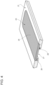
- each exit window 23 comprise and/or defines a window 25 comprising carbon. In even more detail, each exit window 23 comprise and/or defines a window 25 consisting of carbon.
- the window includes and/or consists of graphite.
- the window includes and/or consists of a graphite foil.
- each inner space 22 may be under vacuum.
- each main housing 21 may comprise an opening and the respective window 25 may fully cover opening, in particular such that each particle associated to the respective irradiation beam, in particular the respective electron beam, must pass through the respective window 25 so as to exit from the respective main housing 21.
- exit window 23 defines window 25 (namely, they coincide).
- window 25 may comprise and/or consist of a pyrolytic graphite foil and/or of an artificial graphite foil and/or of a pyrolytic carbon foil and/or a highly oriented pyrolytic graphite sheet and/or may comprise a graphene foil.
- graphite is a crystalline form of carbon with its atoms being arranged in a hexagonal structure.
- pyrolytic graphite comprises a plurality of graphene layers, in particular graphene being an allotrope of carbon.
- each atom in each graphene layer may be connected to its respective three nearest neighbor atoms, in particular by a ⁇ -bond. Additionally, each atom may contribute one electron to a conduction band that extends over the whole graphene layer, i.e. in a delocalized ⁇ -bond.
- the plurality of graphene layers of the pyrolytic graphite stack to one another by means of Wan der Waals interactions between one or more of the graphene layers and form graphitic domains.
- pyrolytic or artificial graphite is a graphite material with a high degree of preferred crystallographic orientation with regard to an axis perpendicular to the surface of a substrate (in the present case and according to some possible embodiments of window 25).
- Pyrolytic graphite may be obtained by graphitization heat treatment of a carbon containing material or by chemical vapor deposition, preferably at temperatures above 2500K.
- HOPG highly oriented pyrolytic graphite
- window 25 having carbon presents an excellent temperature behavior.
- exit window 23 heats, in use, to much lower temperatures in comparison to the state-of-the-art exit windows relying on titanium.
- the Applicant has observed that while at a power level of 3 kW the temperature of a respective titanium foil of the state-of-the-art exit windows reaches about 300 °C, while window 25 reaches about 100 °C only.
- each window 25 may have a thickness below 50 um, preferentially below 30 um.
- each window 25 may have a thickness of more than 5 ⁇ m, in particular of more than 8 ⁇ m, even more particular of more than 12 um.
- Figure 5 illustrates results from simulations (considering an energy of 80 kV), in particular Monte Carlo simulations, showing the dependence of the thickness of window 25 on a surface dose.
- the results for the varying thickness of window 25 are normalized in view of the results originating when considering a window (comprising titanium) known from the state-of-the-art.
- the respective curve depicting the behavior when considering the window known in the state-of-the-art is shown in bold-black color.
- the dashed-curve depicts the curve when considering window 25 having a thickness of 25 ⁇ m
- the black curve depicts the curve when considering window 25 having a thickness of 12 um
- the grey curve depicts the curve when considering window 25 having a thickness of 18 um.
- Good working results are obtained with thicknesses below 50 um with preferred thicknesses lying below 30 ⁇ . Indeed, the Applicant has also found that a peak of efficiency reverts below a thickness of 12 um.
- the Applicant has also verified the results from the simulations with dosimetry measurements.
- each exit window 23 may comprise a support structure 27 carrying the respective window 25.
- each support structure 27 may comprise a plurality of apertures.
- each support structure 27 may comprise a plurality of ribs spaced apart from one another and defining the apertures.
- each support structure 27 may comprise, in particular consist of, copper.
- each main housing 21 may also comprise a housing seat for the respective exit window 23 and within which the respective exit window 23 is positioned in.
- each housing may comprise an annular cooling channel 29 for a cooling fluid, in particular for cooling the respective exit window 23.
- a portion of the respective exit window 23, in particular the respective support structure 27, may cover the respective cooling channel.
- each main housing 21 may also comprise a respective fastening assembly so as to fasten the respective exit window 23 within the respective housing seat.
- each irradiation transmission source 24 may comprise a cathode 31 and an electron generating filament (not shown), in particular surrounded by the respective cathode 31.
- each exit window 23 may act as the anode.
- tube forming and sealing device 10 may comprise at least two forming ring assemblies 35, in particular arranged within inner environment 9, being configured to gradually fold in cooperation with one another packaging material 3 into tube 11, in particular by overlapping the edges of packaging material 3 with one another.
- tube forming and sealing device 10 may comprise a sealing head 36, in particular arranged within inner environment 9 and, configured to longitudinally seal tube 11.
- filling device 12 may comprise a filling pipe 37 being configured to direct, in use, the pourable product into tube 11.
- filling pipe 37 may, in use, be at least partially placed within tube 11 for feeding, in use, the pourable product into tube 11.
- package forming apparatus 13 may comprise:
- package forming apparatus 12 may be configured to control the forming and sealing assemblies and the conveying unit such to transversally seal and cut tube 11 along equally spaced transversal cross sections.
- packaging machine 1 produces packages 2 of a pourable food product.
- packaging machine 1 forms tube 11 from packaging material 3, longitudinally seals tube 11, fills tube 11 with the pourable product and forms, transversally seals and transversally cuts tube 11 so as to obtain packages 2.
- packaging material 3 Prior to the formation of tube 11 from packaging material 3, packaging material 3 is sterilized by sterilization apparatus 7.
- respective irradiation beams in particular respective electron beams, are directed onto first face 4 and second face 5.
- Each irradiation beam in particular each electron beam, is generated by the respective irradiation beam emitting device 20. Thereby, the respective irradiation beam is generated by the respective irradiation transmission source 24 and exits through the respective exit window 23.
- pyrolytic graphite exit window 23 heats up, in use, to lower temperatures when compared to the known solutions and when operating at the same power. This means that irradiation beam emitting devices 20 can operate with higher maximum energies, which facilitates the overall sterilization process.
- pyrolytic graphite is a relatively cheap material.
- the exit window 23 comprises a window 25 including artificial graphite.
- the exit window 25 comprising artificial graphite presents an excellent temperature behavior.
- the exit window 23 heats, in use, to much lower temperatures in comparison to the state-of-the-art exit windows relying on titanium.
- the Applicant has observed that while at a power level of 3 kW the temperature of a respective titanium foil of the state-of-the-art exit windows reaches about 300-400 °C, while window 25 reaches about 100 °C.
- the artificial graphite allows for a robust window 25, insofar as the window 25 can resist the mechanical stress due to the generated vacuum.
- the exit window 23 may comprise a coating covering the window 25, preferably the coating being configured to prevent oxidation of the window 25.
- a layer of coating can protect the window 25 from mechanical and/or chemical interaction with the environment.
- the coating can advantageously avoid the oxidation of the carbon within the window 25.
- the window 25 may have a thickness between 10 um and 50 ⁇ m, preferably between 12 um and 50 ⁇ m, even more preferably between 15 um and 30 um.
- the window may have a thickness between 10 um and 100 ⁇ m, in case e.g. of highly crystalized material such as HOPG.
- the thicknesses may allow transmission of electrons outside of the exit window and at the same time may be greater than traditional exit windows, e.g. of 7 um. Accordingly, the manufacturing of the exit window 25 is easier.
Landscapes
- Health & Medical Sciences (AREA)
- Engineering & Computer Science (AREA)
- Mechanical Engineering (AREA)
- General Health & Medical Sciences (AREA)
- Epidemiology (AREA)
- Animal Behavior & Ethology (AREA)
- Life Sciences & Earth Sciences (AREA)
- Public Health (AREA)
- Veterinary Medicine (AREA)
- Toxicology (AREA)
- Physics & Mathematics (AREA)
- General Engineering & Computer Science (AREA)
- High Energy & Nuclear Physics (AREA)
- Apparatus For Disinfection Or Sterilisation (AREA)
Applications Claiming Priority (1)
| Application Number | Priority Date | Filing Date | Title |
|---|---|---|---|
| EP22170005 | 2022-04-26 |
Publications (2)
| Publication Number | Publication Date |
|---|---|
| EP4279403A2 true EP4279403A2 (fr) | 2023-11-22 |
| EP4279403A3 EP4279403A3 (fr) | 2024-04-03 |
Family
ID=81387113
Family Applications (1)
| Application Number | Title | Priority Date | Filing Date |
|---|---|---|---|
| EP23168903.5A Pending EP4279403A3 (fr) | 2022-04-26 | 2023-04-20 | Appareil de stérilisation ayant un dispositif d'émission de faisceau d'irradiation et machine d'emballage dotée d'un appareil de stérilisation |
Country Status (5)
| Country | Link |
|---|---|
| US (1) | US20250187772A1 (fr) |
| EP (1) | EP4279403A3 (fr) |
| JP (1) | JP2025513992A (fr) |
| CN (1) | CN118922355A (fr) |
| WO (1) | WO2023208707A2 (fr) |
Family Cites Families (15)
| Publication number | Priority date | Publication date | Assignee | Title |
|---|---|---|---|---|
| US3105916A (en) * | 1960-09-08 | 1963-10-01 | High Voltage Engineering Corp | Radiation beam window |
| US3916200A (en) * | 1974-09-04 | 1975-10-28 | Us Energy | Window for radiation detectors and the like |
| US4409511A (en) * | 1981-02-23 | 1983-10-11 | Rpc Industries | Phase transition cooled window for broad beam electron gun |
| US5378898A (en) * | 1992-09-08 | 1995-01-03 | Zapit Technology, Inc. | Electron beam system |
| US5788940A (en) * | 1996-10-23 | 1998-08-04 | Tetra Laval Holdings & Finance Sa | Method and apparatus for sterilizing cartons through ultraviolet irradiation |
| JP3736075B2 (ja) * | 1997-10-14 | 2006-01-18 | 株式会社Nhvコーポレーション | 電子線照射装置において被照射物を照射領域より逃がす方法 |
| JP2001221899A (ja) * | 2000-02-07 | 2001-08-17 | Ebara Corp | 電子線照射装置 |
| SE525347C2 (sv) * | 2003-06-19 | 2005-02-08 | Tetra Laval Holdings & Finance | Förfarande och anordning för bestrålning med elektroner |
| DE112004002771A5 (de) * | 2004-03-02 | 2008-08-28 | Comet Holding Ag | Röntgenröhre für hohe Dosisleistungen, Verfahren zur Erzeugung von hohen Dosisleistungen mit Röntgenröhren sowie ein Verfahren zur Herstellung entsprechender Röntgenvorrichtungen |
| EP2279760B1 (fr) * | 2008-05-12 | 2014-03-19 | Hitachi, Ltd. | Dispositif d'irradiation par faisceau d'électrons pour la stérilisation de matériau en feuille |
| SE533567C2 (sv) * | 2009-03-11 | 2010-10-26 | Tetra Laval Holdings & Finance | Förfarande för montering av ett fönster för utgående elektroner och en fönsterenhet för utgående elektroner |
| MX2012008598A (es) * | 2010-02-08 | 2012-08-15 | Tetra Laval Holdings & Finance | Ensamblaje y metodo para reducir arrugas en una lamina metalica en un arreglo circular. |
| WO2013004564A1 (fr) * | 2011-07-04 | 2013-01-10 | Tetra Laval Holdings & Finance S.A. | Émetteur de faisceaux d'électrons comprenant une joue de refroidissement, et procédé de refroidissement d'un émetteur de faisceaux d'électrons |
| JP6100036B2 (ja) * | 2013-03-12 | 2017-03-22 | キヤノン株式会社 | 透過型ターゲットおよび該透過型ターゲットを備える放射線発生管、放射線発生装置、及び、放射線撮影装置 |
| WO2019229069A1 (fr) * | 2018-06-01 | 2019-12-05 | Tetra Laval Holdings & Finance S.A. | Machine d'emballage et procédé de production d'emballages scellés |
-
2023
- 2023-04-20 WO PCT/EP2023/060260 patent/WO2023208707A2/fr not_active Ceased
- 2023-04-20 EP EP23168903.5A patent/EP4279403A3/fr active Pending
- 2023-04-20 US US18/845,198 patent/US20250187772A1/en active Pending
- 2023-04-20 JP JP2024549735A patent/JP2025513992A/ja active Pending
- 2023-04-20 CN CN202380028664.6A patent/CN118922355A/zh active Pending
Also Published As
| Publication number | Publication date |
|---|---|
| WO2023208707A2 (fr) | 2023-11-02 |
| JP2025513992A (ja) | 2025-05-02 |
| WO2023208707A3 (fr) | 2023-12-14 |
| US20250187772A1 (en) | 2025-06-12 |
| EP4279403A3 (fr) | 2024-04-03 |
| CN118922355A (zh) | 2024-11-08 |
Similar Documents
| Publication | Publication Date | Title |
|---|---|---|
| RU2726545C1 (ru) | Опора для поперечного запечатывания трубы из упаковочного материала и сварочные зажимные губки с опорой | |
| CA2121614C (fr) | Accelerateur d'electrons pour la sterilisation du materiel a emballer dans un appareil d'emballage aseptique | |
| US8344332B2 (en) | Electron beam irradiation apparatus for sterilizing sheet material | |
| EP3620293A1 (fr) | Procédé de formation d'un tube et procédé et machine d'emballage pour former un emballage | |
| CN1289149C (zh) | 制造可灌装食品密封包装的包装片材的杀菌方法 | |
| EP0310900B1 (fr) | Dispositif de stérilisation de matière en feuille | |
| MX2008015251A (es) | Metodo de esterilizacion de empaques. | |
| EP4279403A2 (fr) | Appareil de stérilisation ayant un dispositif d'émission de faisceau d'irradiation et machine d'emballage dotée d'un appareil de stérilisation | |
| EP3708506A1 (fr) | Machine d'emballage pour produire des emballages scellés | |
| WO2024047023A2 (fr) | Machine d'emballage et procédé de formation d'emballages | |
| US6685883B2 (en) | Method and unit for sterilizing packaging sheet material for manufacturing sealed packages of pourable food products | |
| EP0876279B1 (fr) | Methode de sterilisation de recipients clos | |
| JP6386135B2 (ja) | 無菌包装物を製造する方法 | |
| JP2008230668A (ja) | シート材料の殺菌用電子線照射装置 | |
| EP4219321B1 (fr) | Machine d'emballage et procédé de formation d'emballages | |
| JP6232527B2 (ja) | 飲料又は食品の無菌包装装置 | |
| EP4717444A1 (fr) | Dispositif d'enclume de scellage, dispositif de scellage, appareil de formation d'emballage pour une machine d'emballage et machine d'emballage pour former des emballages remplis d'un produit fluide | |
| US20250296718A1 (en) | Multilayer rod, sealing unit, package forming apparatus, packaging machine, method for manufacturing a multilater rod and method for manufacturing an induction sealing device | |
| JPH1135015A (ja) | 中空状包材の滅菌装置 | |
| JPH107113A (ja) | 無菌包装方法および連続包装袋 | |
| WO2022078753A1 (fr) | Élément de pression et dispositif d'étanchéité pour un ensemble d'emballage comportant un élément de pression | |
| HK1065264B (en) | Method for sterilizing packaging sheet material for manufacturing sealed packages of pourable food products |
Legal Events
| Date | Code | Title | Description |
|---|---|---|---|
| PUAI | Public reference made under article 153(3) epc to a published international application that has entered the european phase |
Free format text: ORIGINAL CODE: 0009012 |
|
| STAA | Information on the status of an ep patent application or granted ep patent |
Free format text: STATUS: THE APPLICATION HAS BEEN PUBLISHED |
|
| AK | Designated contracting states |
Kind code of ref document: A2 Designated state(s): AL AT BE BG CH CY CZ DE DK EE ES FI FR GB GR HR HU IE IS IT LI LT LU LV MC ME MK MT NL NO PL PT RO RS SE SI SK SM TR |
|
| PUAL | Search report despatched |
Free format text: ORIGINAL CODE: 0009013 |
|
| AK | Designated contracting states |
Kind code of ref document: A3 Designated state(s): AL AT BE BG CH CY CZ DE DK EE ES FI FR GB GR HR HU IE IS IT LI LT LU LV MC ME MK MT NL NO PL PT RO RS SE SI SK SM TR |
|
| RIC1 | Information provided on ipc code assigned before grant |
Ipc: B65B 9/12 20060101ALI20240223BHEP Ipc: B65B 55/02 20060101ALI20240223BHEP Ipc: A61L 2/08 20060101ALI20240223BHEP Ipc: B65B 55/08 20060101ALI20240223BHEP Ipc: B65B 55/16 20060101AFI20240223BHEP Ipc: B65B 9/20 20120101ALI20240223BHEP Ipc: G21K 5/00 20060101ALI20240223BHEP |
|
| STAA | Information on the status of an ep patent application or granted ep patent |
Free format text: STATUS: REQUEST FOR EXAMINATION WAS MADE |
|
| 17P | Request for examination filed |
Effective date: 20241004 |
|
| RBV | Designated contracting states (corrected) |
Designated state(s): AL AT BE BG CH CY CZ DE DK EE ES FI FR GB GR HR HU IE IS IT LI LT LU LV MC ME MK MT NL NO PL PT RO RS SE SI SK SM TR |