EP4279741B1 - Système de compression de gaz et procédé de récupération de l'hydrogène - Google Patents
Système de compression de gaz et procédé de récupération de l'hydrogène Download PDFInfo
- Publication number
- EP4279741B1 EP4279741B1 EP22174128.3A EP22174128A EP4279741B1 EP 4279741 B1 EP4279741 B1 EP 4279741B1 EP 22174128 A EP22174128 A EP 22174128A EP 4279741 B1 EP4279741 B1 EP 4279741B1
- Authority
- EP
- European Patent Office
- Prior art keywords
- metal hydride
- gas
- pressure
- compressor
- leakage gas
- Prior art date
- Legal status (The legal status is an assumption and is not a legal conclusion. Google has not performed a legal analysis and makes no representation as to the accuracy of the status listed.)
- Active
Links
Images


Classifications
-
- F—MECHANICAL ENGINEERING; LIGHTING; HEATING; WEAPONS; BLASTING
- F04—POSITIVE - DISPLACEMENT MACHINES FOR LIQUIDS; PUMPS FOR LIQUIDS OR ELASTIC FLUIDS
- F04B—POSITIVE-DISPLACEMENT MACHINES FOR LIQUIDS; PUMPS
- F04B41/00—Pumping installations or systems specially adapted for elastic fluids
-
- F—MECHANICAL ENGINEERING; LIGHTING; HEATING; WEAPONS; BLASTING
- F04—POSITIVE - DISPLACEMENT MACHINES FOR LIQUIDS; PUMPS FOR LIQUIDS OR ELASTIC FLUIDS
- F04B—POSITIVE-DISPLACEMENT MACHINES FOR LIQUIDS; PUMPS
- F04B37/00—Pumps having pertinent characteristics not provided for in, or of interest apart from, groups F04B25/00 - F04B35/00
- F04B37/10—Pumps having pertinent characteristics not provided for in, or of interest apart from, groups F04B25/00 - F04B35/00 for special use
- F04B37/18—Pumps having pertinent characteristics not provided for in, or of interest apart from, groups F04B25/00 - F04B35/00 for special use for specific elastic fluids
-
- C—CHEMISTRY; METALLURGY
- C01—INORGANIC CHEMISTRY
- C01B—NON-METALLIC ELEMENTS; COMPOUNDS THEREOF; METALLOIDS OR COMPOUNDS THEREOF NOT COVERED BY SUBCLASS C01C
- C01B3/00—Hydrogen; Gaseous mixtures containing hydrogen; Separation of hydrogen from mixtures containing it; Purification of hydrogen; Reversible storage of hydrogen
- C01B3/0005—Reversible storage of hydrogen, e.g. by hydrogen getters or electrodes
- C01B3/001—Reversible storage of hydrogen, e.g. by hydrogen getters or electrodes characterised by the uptaking media; Treatment thereof
- C01B3/0018—Inorganic elements or compounds, e.g. oxides, nitrides, borohydrides or zeolites; Solutions thereof
- C01B3/0031—Intermetallic compounds; Metal alloys
- C01B3/0036—Intermetallic compounds; Metal alloys only containing iron and titanium
-
- C—CHEMISTRY; METALLURGY
- C01—INORGANIC CHEMISTRY
- C01B—NON-METALLIC ELEMENTS; COMPOUNDS THEREOF; METALLOIDS OR COMPOUNDS THEREOF NOT COVERED BY SUBCLASS C01C
- C01B3/00—Hydrogen; Gaseous mixtures containing hydrogen; Separation of hydrogen from mixtures containing it; Purification of hydrogen; Reversible storage of hydrogen
- C01B3/0005—Reversible storage of hydrogen, e.g. by hydrogen getters or electrodes
- C01B3/001—Reversible storage of hydrogen, e.g. by hydrogen getters or electrodes characterised by the uptaking media; Treatment thereof
- C01B3/0018—Inorganic elements or compounds, e.g. oxides, nitrides, borohydrides or zeolites; Solutions thereof
- C01B3/0031—Intermetallic compounds; Metal alloys
- C01B3/0047—Intermetallic compounds; Metal alloys containing a rare earth metal
-
- F—MECHANICAL ENGINEERING; LIGHTING; HEATING; WEAPONS; BLASTING
- F04—POSITIVE - DISPLACEMENT MACHINES FOR LIQUIDS; PUMPS FOR LIQUIDS OR ELASTIC FLUIDS
- F04B—POSITIVE-DISPLACEMENT MACHINES FOR LIQUIDS; PUMPS
- F04B37/00—Pumps having pertinent characteristics not provided for in, or of interest apart from, groups F04B25/00 - F04B35/00
- F04B37/02—Pumps having pertinent characteristics not provided for in, or of interest apart from, groups F04B25/00 - F04B35/00 for evacuating by absorption or adsorption
- F04B37/04—Selection of specific absorption or adsorption materials
-
- F—MECHANICAL ENGINEERING; LIGHTING; HEATING; WEAPONS; BLASTING
- F04—POSITIVE - DISPLACEMENT MACHINES FOR LIQUIDS; PUMPS FOR LIQUIDS OR ELASTIC FLUIDS
- F04B—POSITIVE-DISPLACEMENT MACHINES FOR LIQUIDS; PUMPS
- F04B39/00—Component parts, details, or accessories, of pumps or pumping systems specially adapted for elastic fluids, not otherwise provided for in, or of interest apart from, groups F04B25/00 - F04B37/00
- F04B39/06—Cooling; Heating; Prevention of freezing
-
- F—MECHANICAL ENGINEERING; LIGHTING; HEATING; WEAPONS; BLASTING
- F04—POSITIVE - DISPLACEMENT MACHINES FOR LIQUIDS; PUMPS FOR LIQUIDS OR ELASTIC FLUIDS
- F04B—POSITIVE-DISPLACEMENT MACHINES FOR LIQUIDS; PUMPS
- F04B41/00—Pumping installations or systems specially adapted for elastic fluids
- F04B41/02—Pumping installations or systems specially adapted for elastic fluids having reservoirs
-
- F—MECHANICAL ENGINEERING; LIGHTING; HEATING; WEAPONS; BLASTING
- F04—POSITIVE - DISPLACEMENT MACHINES FOR LIQUIDS; PUMPS FOR LIQUIDS OR ELASTIC FLUIDS
- F04B—POSITIVE-DISPLACEMENT MACHINES FOR LIQUIDS; PUMPS
- F04B49/00—Control, e.g. of pump delivery, or pump pressure of, or safety measures for, machines, pumps, or pumping installations, not otherwise provided for, or of interest apart from, groups F04B1/00 - F04B47/00
- F04B49/08—Regulating by delivery pressure
-
- F—MECHANICAL ENGINEERING; LIGHTING; HEATING; WEAPONS; BLASTING
- F17—STORING OR DISTRIBUTING GASES OR LIQUIDS
- F17C—VESSELS FOR CONTAINING OR STORING COMPRESSED, LIQUEFIED OR SOLIDIFIED GASES; FIXED-CAPACITY GAS-HOLDERS; FILLING VESSELS WITH, OR DISCHARGING FROM VESSELS, COMPRESSED, LIQUEFIED, OR SOLIDIFIED GASES
- F17C5/00—Methods or apparatus for filling containers with liquefied, solidified, or compressed gases under pressures
- F17C5/06—Methods or apparatus for filling containers with liquefied, solidified, or compressed gases under pressures for filling with compressed gases
-
- F—MECHANICAL ENGINEERING; LIGHTING; HEATING; WEAPONS; BLASTING
- F17—STORING OR DISTRIBUTING GASES OR LIQUIDS
- F17C—VESSELS FOR CONTAINING OR STORING COMPRESSED, LIQUEFIED OR SOLIDIFIED GASES; FIXED-CAPACITY GAS-HOLDERS; FILLING VESSELS WITH, OR DISCHARGING FROM VESSELS, COMPRESSED, LIQUEFIED, OR SOLIDIFIED GASES
- F17C2221/00—Handled fluid, in particular type of fluid
- F17C2221/01—Pure fluids
- F17C2221/012—Hydrogen
-
- F—MECHANICAL ENGINEERING; LIGHTING; HEATING; WEAPONS; BLASTING
- F17—STORING OR DISTRIBUTING GASES OR LIQUIDS
- F17C—VESSELS FOR CONTAINING OR STORING COMPRESSED, LIQUEFIED OR SOLIDIFIED GASES; FIXED-CAPACITY GAS-HOLDERS; FILLING VESSELS WITH, OR DISCHARGING FROM VESSELS, COMPRESSED, LIQUEFIED, OR SOLIDIFIED GASES
- F17C2227/00—Transfer of fluids, i.e. method or means for transferring the fluid; Heat exchange with the fluid
- F17C2227/01—Propulsion of the fluid
- F17C2227/0128—Propulsion of the fluid with pumps or compressors
- F17C2227/0157—Compressors
- F17C2227/0164—Compressors with specified compressor type, e.g. piston or impulsive type
-
- Y—GENERAL TAGGING OF NEW TECHNOLOGICAL DEVELOPMENTS; GENERAL TAGGING OF CROSS-SECTIONAL TECHNOLOGIES SPANNING OVER SEVERAL SECTIONS OF THE IPC; TECHNICAL SUBJECTS COVERED BY FORMER USPC CROSS-REFERENCE ART COLLECTIONS [XRACs] AND DIGESTS
- Y02—TECHNOLOGIES OR APPLICATIONS FOR MITIGATION OR ADAPTATION AGAINST CLIMATE CHANGE
- Y02E—REDUCTION OF GREENHOUSE GAS [GHG] EMISSIONS, RELATED TO ENERGY GENERATION, TRANSMISSION OR DISTRIBUTION
- Y02E60/00—Enabling technologies; Technologies with a potential or indirect contribution to GHG emissions mitigation
- Y02E60/30—Hydrogen technology
- Y02E60/32—Hydrogen storage
-
- Y—GENERAL TAGGING OF NEW TECHNOLOGICAL DEVELOPMENTS; GENERAL TAGGING OF CROSS-SECTIONAL TECHNOLOGIES SPANNING OVER SEVERAL SECTIONS OF THE IPC; TECHNICAL SUBJECTS COVERED BY FORMER USPC CROSS-REFERENCE ART COLLECTIONS [XRACs] AND DIGESTS
- Y02—TECHNOLOGIES OR APPLICATIONS FOR MITIGATION OR ADAPTATION AGAINST CLIMATE CHANGE
- Y02E—REDUCTION OF GREENHOUSE GAS [GHG] EMISSIONS, RELATED TO ENERGY GENERATION, TRANSMISSION OR DISTRIBUTION
- Y02E60/00—Enabling technologies; Technologies with a potential or indirect contribution to GHG emissions mitigation
- Y02E60/30—Hydrogen technology
- Y02E60/50—Fuel cells
Definitions
- the present invention relates to a gas compression system, a method for recovering hydrogen which is produced as leak gas in a compressor, and a hydrogen filling station comprising a gas compression system as described below.
- Hydrogen filling stations are used to refuel fuel cell vehicles with hydrogen fuel.
- State-of-the-art hydrogen filling stations are designed in such a way that the hydrogen is taken from a storage tank containing the hydrogen, pressurized in a compressor and fed into the hydrogen vehicle. Due to the low molecular weight (also known as molar mass, molar mass or mass per unit of substance) of hydrogen, the compression of hydrogen is technically challenging, especially with larger volume flows.
- Hydrogen gas that is to be filled into a fuel cell vehicle now requires a high level of purity and a high pressure, in particular of more than 400 bar.
- the EP 3 121 446 A1 describes an oil-lubricated piston compressor for compressing hydrogen and a refueling system for delivering hydrogen at high pressure to a fuel cell-powered vehicle.
- the disadvantage of using such an oil-lubricated piston compressor is that the oil content in the emitted hydrogen gas must be reduced as much as possible before delivery to a consumer in order not to impair the functioning of the fuel cell or even to avoid damaging it.
- appropriately designed separating devices and/or filters are used, which are arranged downstream of the last compression stage. The requirement for separating devices and/or filters to separate lubricant from the compressed hydrogen leads to increased maintenance effort for such gas compression systems and ultimately to higher operating costs.
- Piston compressors known from the state of the art often cannot be built in a pressure-encapsulated manner, which means that a certain amount of leakage of the medium to be compressed into the environment must be accepted.
- the JP 2011-132876 A a piston compressor for compressing hydrogen, where the leakage of hydrogen from the compressor into the environment is accepted. Due to the flammability and the ability to form explosive mixtures, such a system - in addition to the waste of valuable resources and the associated economic disadvantages - also presents a considerable safety risk depending on where the compressor is used.
- the WO 2015/074740 A1 a leakage return line, which runs from the interior of the piston compressor housing to the inlet on the first cylinder head of the compressor.
- the housing of the piston compressor is therefore designed to be pressure-resistant at least up to the suction pressure of the first compressor stage.
- the disadvantage of a pressure-resistant solution is that the design effort and the investment costs are comparatively higher than is the case with non-pressure-resistant compressor housings.
- the problem of the uncontrolled release of hydrogen into the environment is not satisfactorily solved by such a system, since the The static seals used therein only partially enable leak-free sealing of the hydrogen overpressure present in the housing.
- the present invention is based on the object of eliminating these and other disadvantages of the prior art and in particular of providing a gas compression system for compressing hydrogen which is reliable and low-maintenance and can be operated at low costs, including the costs of electricity consumption.
- the object is achieved in particular with a gas compression system having a compressor for compressing hydrogen.
- the compressor has a leak gas discharge line for discharging the hydrogen, which is produced as leak gas during compression, from the compressor.
- the gas compression system also has at least one recovery device for recovering the hydrogen, which is produced as leak gas during compression, and a leak gas return line.
- the leak gas return line is designed to return the leak gas recovered by the at least one recovery device to a location in the gas compression system upstream of the compressor.
- the leak gas return line is designed to return the leak gas recovered by the at least one recovery device to the suction line of a compressor stage of the compressor.
- Each recovery device can be fluidically connected to the leak gas discharge line and the leak gas return line and each has at least one metal hydride storage device.
- Each metal hydride storage unit is thermally coupled to a heat exchanger and has at least one hydride-forming metal alloy which is designed for the cyclical de- or absorption of the leakage gas with heat supply or heat removal through the respective heat exchanger.
- the recovery devices present in the gas compression system are designed to increase the leakage gas pressure ( p L ) prevailing in the leakage gas discharge line to at least the pressure ( p ) prevailing at the point of the gas compression system and/or to at least the suction pressure ( p s ) prevailing in the suction line of the compressor stage.
- the use of metal hydrides represents a promising method for hydrogen compression, which requires no moving parts and only a low energy requirement.
- the method uses a reversible heat-driven interaction of a hydride-forming metal, an alloy or an intermetallic compound with hydrogen gas to form a metal hydride.
- the exothermic formation of the metal hydride is promoted by the absorption of low-pressure hydrogen in the hydride-forming material at a low temperature, i.e. with heat removal from the hydride-forming material.
- the endothermic decomposition of the metal hydride is promoted by the desorption of high-pressure hydrogen from the metal hydride at a higher temperature, i.e. with heat supply to the metal hydride.
- periodic low-pressure hydrogen absorption or high-pressure hydrogen desorption can be achieved by periodically cooling and heating the hydride-forming material or the metal hydride, similar to the suction and pressure processes in a mechanical compressor.
- a device based on this principle is therefore also referred to below as a metal hydride compressor.
- a “compressor for compressing hydrogen” (hereinafter referred to simply as “compressor”) is understood to mean a device for increasing the pressure and density of the hydrogen used as the working gas of the compressor, for example a reciprocating piston compressor, an ionic compressor, a screw compressor or a diaphragm compressor, but with the proviso that the compressor is not a metal hydride compressor.
- the at least one recovery device for increasing the leakage gas pressure to the suction pressure is a single- or multi-stage metal hydride compressor.
- the gas compression system according to the invention has a simple configuration, is reliable, low-maintenance and enables periodically operated hydrogen recovery with low Operating costs.
- the use of metal hydride storage also makes it possible to achieve high compression ratios with low power consumption and a high purity of the recovered hydrogen.
- the compressor of the gas compression system according to the invention can in particular also be a multi-stage compressor with a plurality of compressor stages which are configured for the step-by-step compression of the working gas.
- the leak gas return line is designed to return the leak gas recovered by the at least one recovery device to the suction line of a first compressor stage of the compressor.
- the pressure of the leak gas only has to be increased to the relatively low pressure that prevails in the suction line of the first compressor stage, for example to a pressure of approximately 30 bar.
- the gas compression system comprises a first recovery device and a second recovery device, which are connected in parallel, so that a temporally independent loading and unloading of the metal hydride storage devices arranged in the respective recovery devices is possible.
- Another problem that arises from operating a metal hydride compressor in a wider temperature range is the high thermal stresses that occur in the metal hydride storage tanks at the beginning of the heating and cooling half-cycles. If one takes into account the additional stresses that arise from the increase in gas pressure during hydride desorption (heating) and the increase in the volume of the hydride-forming metal alloys during hydride formation (cooling), the probability of damage to the metal hydride storage tanks, for example through cracking, increases, which significantly reduces the service life and the safety of operation.
- each recovery device has a plurality of metal hydride storage devices.
- the metal hydride storage devices are connected in series with one another, viewed in the flow direction of the leakage gas flow, and are each thermally coupled to a heat exchanger.
- the metal hydride storage devices connected in series each have at least one hydride-forming metal alloy, which are designed for the cyclical de- or absorption of hydrogen with heat supply or heat removal through the respective heat exchanger.
- the first metal hydride storage device arranged first in the flow direction in each recovery device is designed to increase the pressure of the leakage gas from the leakage gas pressure (p L ) to a first intermediate pressure (p 1 ) which is higher than the leakage gas pressure (p L ).
- the last metal hydride storage device arranged last in the flow direction in each recovery device is designed to increase the pressure of the leakage gas to the suction pressure (p s ).
- the metal hydride storage tanks arranged between the first and the last metal hydride storage tanks are each designed to gradually increase the pressure of the leak gas to an intermediate pressure (p 2 , P 3 ... p n ) which is higher than the first intermediate pressure (p 1 ).
- flow direction always refers to the flow direction of the leakage gas flow in the gas compression system according to the invention.
- the metal hydride storage units connected in series each have a different hydride-forming metal alloy. This allows a higher compression ratio to be achieved.
- the metal hydride storage units connected in series contain different hydride-forming metal alloys, wherein the thermal stability of the hydrogenated metal alloys decreases in the flow direction, i.e. in comparison to the previously arranged metal hydride storage unit.
- each recovery device preferably has only two metal hydride storage units.
- the compressor of the gas compression system is designed as a piston compressor, whereby the gas compression system according to the invention can also be transferred to or retrofitted to widely used, existing compressors.
- the compressor of the gas compression system is designed as a dry-running piston compressor.
- Dry-running piston compressors are compressors that have operate without external lubricants, such as lubricating oil. This significantly reduces the risk of contamination of the compressed hydrogen by lubricants.
- the hydride-forming metal alloys of the metal hydride storage have a dissociation pressure of at least 30 bar, preferably at least 35 bar, and particularly preferably at least 40 bar at a temperature of 60-100 °C.
- the measurement of the dissociation pressure is known to the person skilled in the art from the prior art, for example from the publication by T. Matsunaga et al. "TiCrVMo alloys with high dissociation pressure for high-pressure MH tank", International Journal of Hydrogen Energy, Vol. 34 (2009), 1458-1462 , which are referred to here (see Section 2, "Experimental").
- the hydride-forming metal alloys are selected from the group comprising LaNi 5 , ZrV 2 , ZrMn 2 , TiMn 2 , FeTi, Zr 2 Co and Ti 2 Ni.
- the hydride-forming metal alloys are selected from the group comprising LaNi 5 , ZrV 2 , ZrMn 2 and TiMn 2 .
- the metal alloys mentioned above have the advantage that, in particular by combining two or more of the metal alloys mentioned above, a large working pressure range, which is defined by the difference between the leakage gas pressure (p L ) and the suction pressure (p s ), can be adjusted using alloy technology.
- the compressor has a housing which is essentially designed to be pressure-resistant only up to 40 bar.
- the housing of the compressor is preferably designed to be pressure-resistant only up to 15 bar, and particularly preferably only up to 2 bar.
- Such a housing is particularly simple in construction and can be produced inexpensively.
- the gas compression system according to the invention has no containers for storing the leak gas downstream of the at least one recovery device and before the leak gas is returned to the location in the gas compression system before the compressor.
- the gas compression system downstream of the at least one recovery device and before the leak gas is returned to the location in the gas compression system before the compressor and/or in the suction line of the compressor stage is free of containers for storing the leak gas.
- the gas compression system between the compressor and the at least one recovery device is free of containers for storing the leak gas. In the latter case, the gas compression system thus has - With the exception of the compressor's hydrogen source, there are no containers for storing the leakage gas.
- the heat supply and heat removal to and from the metal hydride storage tanks through the respective heat exchangers is achieved by surrounding the metal hydride storage tanks with a heat transfer medium that is very well insulated from the outside.
- the heat released when the hydrogen gas is stored is transferred to the heat transfer medium and heats it up as well as the metal hydride storage tank itself.
- the volume of the heat transfer medium is dimensioned so that when the metal hydride storage tank is fully loaded, the released heat can be completely absorbed by the heat transfer medium.
- the heat transfer medium of the respective heat exchangers is periodically or continuously exchanged by a suitable conveying device, for example a pump.
- the temperature increase obtained when the metal hydride storage tanks are loaded with hydrogen depends on the loading pressure and the choice of the hydride-forming metal alloy.
- the respective heat exchangers contain a liquid with a boiling temperature of Normal pressure between 30 °C and 180 °C.
- the boiling point of the liquid used as a heat transfer medium is preferably between 90 °C and 130 °C at normal pressure.
- Water, water-glycol mixtures or thermal oils have proven to be particularly suitable heat transfer media, as they are generally readily available and safe to handle.
- metal hydride storage For the general use of metal hydride storage, as described above, a heating system is required to heat the metal hydride storage for discharge. To date, electrical energy or fossil fuels have mostly been used to heat the metal hydride storage.
- a gas cooler that can be cooled with cooling water is connected downstream of the compressor for cooling the hydrogen gas compressed by the compressor.
- the gas cooler and the heat exchangers of the respective recovery devices are connected to one another in such a way that the cooling water heated during the cooling of the gas cooler can be used at least partially to supply heat to the respective metal hydride storage units.
- the leakage gas discharge line has a pressure relief valve.
- the pressure relief valve preferably opens at a pressure of more than 2 bar.
- a pressure relief valve in the leak gas discharge line serves to increase operational safety, since hydrogen, which cannot be absorbed by a recovery device due to a closed valve, for example, cannot accumulate in the leak gas discharge line beyond the load limit of the line.
- each metal hydride storage device has at least one combination valve or a valve pair consisting of an inlet valve upstream of the respective metal hydride storage device in the flow direction and an outlet valve downstream of the respective metal hydride storage device in the flow direction for loading and/or unloading the respective metal hydride storage device with leak gas.
- valve pairs consisting of inlet and outlet valves, which are arranged upstream or downstream of the respective metal hydride storage, has the advantage that the flow direction of the leak gas can be controlled in the at least a recovery device can be maintained and the pressure increase within the recovery devices can be made more efficient, as explained in more detail below.
- the outlet valve of a metal hydride storage unit arranged first in the direction of flow equally represents the inlet valve of a metal hydride storage unit adjacent to this metal hydride storage unit and arranged subsequently in the direction of flow. This can significantly reduce the total number of valves required and further reduce the design effort of the gas compression system.
- the gas compression system also has a control device for controlling the combination valves or the inlet and outlet valves. If inlet and outlet valves are present, these are controlled by the control device in such a way that, in normal use, at least one of the adjacent valves is closed for each valve pair adjacent in the direction of flow in order to exclude a continuous, fluid-conducting connection between the leakage gas discharge line and the leakage gas return line.
- At least one check valve closing against the direction of flow is arranged between the metal hydride storage tanks of the respective recovery device.
- at least one check valve closing against the direction of flow is arranged in the leak gas discharge line.
- Non-return device arranged.
- at least one non-return device closing against the flow direction is arranged in the leakage gas return line.
- a preferred embodiment of the gas compression system according to the invention further comprises a pre-cleaning device for pre-cleaning the hydrogen leak gas before it is fed to the metal hydride storage units.
- a pre-cleaning device for pre-cleaning the impurities that can have a detrimental effect on the service life of the hydride-forming metal alloys are filtered out, converted and/or absorbed.
- the pre-cleaning device contains a capture material (getter material), which is particularly suitable for hydride-forming metals or alloys in which hydride formation only begins significantly above the maximum pressure of the downstream recovery device. This means that no hydride formation takes place on the getter material during the pre-cleaning.
- the pre-cleaning device for pre-cleaning the hydrogen leak gas is arranged in the leak gas discharge line, upstream of any branches that lead to the individual recovery devices, so that the gas compression system can comprise just a single pre-cleaning device. Since the getter material has to be replaced with fresh material from time to time depending on the quality of the leak gas and the required degree of purity of the leak gas cleaned by the pre-cleaning device, the effort required for this can be reduced with a single pre-cleaning device to be maintained. Alternatively or in addition to this, however, it is also conceivable that each recovery device is assigned a pre-cleaning device, which increases the flexibility in the operation and maintenance of the gas compression system.
- the object is further achieved with a method for recovering hydrogen which is produced as leak gas in a compressor.
- the method according to the invention comprises introducing the leak gas into a recovery device with at least one metal hydride storage device with at least one hydride-forming metal alloy (step a); loading the metal hydride storage device with absorption of the introduced leak gas by the metal alloy to form a metal hydride (step b); dissipating the heat released during the formation of the metal hydride through a heat exchanger which is thermally coupled to the metal hydride storage device (step c); heating the metal hydride formed to a predetermined temperature through the heat exchanger with desorption of at least part of the previously absorbed leak gas (step d); discharging the metal hydride storage device and releasing the desorbed leak gas from the recovery device to a leak gas return line.
- Step e) can optionally be carried out with further heating of the metal hydride formed by the heat exchanger.
- the pressure of the leakage gas is increased in step d) - and if the heating of the metal hydride formed continues, possibly also in step e) - by the at least one metal hydride storage device of the recovery device from the leakage gas pressure (p L ) prevailing in the leakage gas discharge line to at least the pressure (p ) prevailing at the location of the gas compression system and/or at least the suction pressure (p s ) prevailing in the suction line of the compressor stage.
- the pressure increase within the recovery device is achieved by appropriate control of inlet and outlet valves which are arranged upstream and downstream of the metal hydride storage device in the flow direction, as will be described in more detail below.
- the process according to the invention for recovering hydrogen described herein is carried out with a gas compression system according to the invention as described herein.
- the pressure increase of the leak gas from the leak gas pressure ( p L ) to the suction pressure ( p s ) takes place in several stages using a plurality of metal hydride storage units connected in series in the recovery device in the direction of flow.
- the first metal hydride storage unit arranged first in the recovery device in the direction of flow increases the pressure of the leak gas from the leak gas pressure ( p L ) to a first intermediate pressure (p 1 ) which is higher than the leak gas pressure (p L ).
- the first intermediate pressure (p 1 ) in the recovery device increases the pressure of the leak gas from the leak gas pressure (p L ) to a first intermediate pressure ( p 1 ) which is higher than the leak gas pressure ( p L ).
- the last metal hydride storage device arranged last in the direction of flow of the recovery device increases the pressure of the leak gas to the suction pressure ( p s ).
- Metal hydride storage devices arranged between the first metal hydride storage device and the last metal hydride storage device increase the pressure of the leak gas step by step to an intermediate pressure ( p 2 , p 3 ... p n ) which is higher than the first intermediate pressure ( p 1 ).
- the process is carried out continuously with cyclic loading and unloading of two recovery devices arranged parallel in the flow direction.
- Each recovery device comprises at least one metal hydride storage device.
- the heating of the metal hydride formed in step d) is carried out at least partially with water which is obtained from the cooling of a gas cooler downstream of the compressor.
- each metal hydride storage device takes place via at least one combination valve or a valve pair consisting of an inlet valve upstream of the respective metal hydride storage device in the flow direction and an outlet valve downstream of the respective metal hydride storage device in the flow direction.
- the respective inlet and outlet valves are controlled by a control device in such a way that a continuous, fluid-conducting connection between the leak gas discharge line and the leak gas return line is excluded.
- a hydrogen filling station comprising a gas compression system as described herein, which is preferably operated with one of the methods described herein.
- Figure 1 shows a flow diagram of a gas compression system 100 according to the invention with a compressor 1 for hydrogen.
- the compressor 1 can be fluidically connected to a hydrogen source Q via a line 3, so that the hydrogen to be compressed can be fed to the compressor 1 via the line 3.
- the gas compression system 100 also comprises a recovery device 10, described in more detail below, for recovering hydrogen which escapes from the compressor 1 as leakage gas during compression.
- a leakage gas discharge line 4 is provided, which can be fluidically connected to the compressor and the leakage gas stream arising during compression.
- the gas compression system 100 also has a leakage gas return line 30 for returning the leakage gas recovered by the recovery device 10 to a point 5 in the gas compression system 100, which is located upstream of the compressor 1 from which the leakage gas originates.
- the leak gas recovered by the recovery device 10 is introduced into the line 3 at the point provided with the reference number 5, which fluidically connects the hydrogen source Q with the compressor 1.
- the leak gas return line 30 has a check element 31, which closes against the flow direction S.
- the recovery device comprises two metal hydride storage units 11a, 11b, each of which contains a hydride-forming metal alloy and is each thermally coupled to a heat exchanger 12a, 12b.
- Cold cooling water which can be provided to the gas compression system 100 from a cooling water source W In via a cooling water pump 50, can be used to cool the two metal hydride storage units 11a, 11b.
- previously heated cooling water ie cooling water which is used in the course of cooling the hydrogen produced by the compressor 1 compressed hydrogen obtained by a gas cooler 7.
- the cold or heated cooling water can be fed to the two metal hydride storage tanks 11a, 11b via three-way valves 19a, 19b. Unused or used cooling water is fed to cooling water drains W out and preferably recycled.
- the recovery device 10 can be fluidically connected to the leak gas discharge line 4 via the inlet valve 13a of the first metal hydride storage tank 11a and to the leak gas return line 30 via the outlet valve 14b of the second metal hydride storage tank 11b.
- the two metal hydride storage tanks 11a, 11b can be fluidically connected to one another via a connecting line 16 and a valve 14a arranged in the connecting line 16 and, viewed in the flow direction S of the leak gas flow, are connected in series.
- the metal hydride storage device 11a arranged first in the flow direction S is designed to increase the leak gas pressure p L prevailing in the leak gas discharge line 4, which is, for example, 2 bar, to a first intermediate pressure p 1 which is higher than the leak gas pressure p L and is, for example, 15 bar.
- the metal hydride storage device 11b arranged last in the flow direction S of the recovery device 10 is designed to increase the first intermediate pressure p 1 , which is provided by the metal hydride storage device 11a arranged upstream of it, to the pressure p prevailing in the line 3, which is, for example, 30 bar.
- the leak gas thus recovered i.e. raised from the leak gas pressure p L to the pressure p , is fed again to the compressor 1 and ultimately delivered to a consumer V, for example to a fuel cell vehicle.
- FIG 2 shows a schematic representation of a metal hydride storage device 11a for use in a gas compression system according to the invention in cross section.
- the metal hydride storage device 11a comprises in the illustrated embodiment a total of twenty-five tubular containers 17a (in Figure 2 shown in cross-section), which are filled with a hydride-forming metal alloy 15a.
- the containers 17a are designed for the inlet and outlet of hydrogen leak gas into the containers 17a, wherein in the case of tubular containers 17a the inlets and outlets are preferably arranged at the opposite ends of the tube.
- the containers 17a containing the hydride-forming metal alloy 15a are surrounded by a heat transfer medium, in particular water or a thermal oil, so that the metal alloy 15a can desorb or adsorb leak gas with heat supply or heat removal through the heat exchanger 12a.
- a heat transfer medium in particular water or a thermal oil
- ribs made of a good heat-conducting material can be arranged on the outer surface of the containers 17a to increase the surface area, which ribs are immersed in the heat transfer medium (not shown).
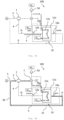
- Figure 3 shows a flow diagram of a further embodiment of a gas compression system 100 according to the invention, which comprises two recovery devices 10, 20 connected in parallel for recovering hydrogen which exits from a compressor 1 as leakage gas.
- the first recovery device 10 comprises the two metal hydride storage devices 11a and 11b connected in series
- the second recovery device 20 comprises the two metal hydride storage devices 21a and 21b connected in series.
- the metal hydride storage device 11a of the first recovery device 10 which is arranged first in the flow direction S, can be fluidically connected to the metal hydride storage device 11b arranged downstream in the flow direction S via connecting line 16 and the valve 14a arranged therein.
- the metal hydride storage device 21a of the second recovery device 20, which is arranged first in the flow direction S, can be fluidically connected to the metal hydride storage device 11b arranged downstream in the flow direction S via connecting line 26 and the valve 24a arranged therein can be fluidically connected to the metal hydride storage device 21b arranged downstream in the flow direction S.
- Hydrogen leak gas which arises during compression by the compressor 1 of the gas compression system 100, is discharged from the compressor 1 through a leak gas discharge line 4 and fed alternately to the respective metal hydride storage devices 11a, 21a via the inlet valve 13a or via the inlet valve 23a, which inlet valves 13a, 23a fluidically connect the first recovery device 10 or the second recovery device 20 to the leak gas discharge line 4, ie the parallel recovery devices 10, 20 operate in push-pull.
- each recovery device 10 the pressure increase of the leakage gas takes place from the leakage gas pressure p L prevailing in the leakage gas discharge line via a first intermediate pressure p 1 to the suction pressure p s prevailing in the suction line 3b of the first compressor stage 5b of the compressor 1, essentially as previously described.
- the metal hydride storage tanks 11a, 11b, 21a, 21b are each thermally coupled to a heat exchanger 12a, 12b, 22a, 22b, wherein the water used to cool or heat the metal hydride storage tanks can be fed to the heat exchangers 12a, 12b, 22a, 22b from a cooling water source W In with cooling water pump 50 or after prior heating by a gas cooler 7 via three-way valves 19a, 19b, 29a, 29b. Unused or used cooling water is fed to cooling water drains W Out and preferably recycled.
- the first recovery device 10 and the second recovery device 20 can be fluidically connected to a leak gas return line 30 via the outlet valves 14b and 24b of the metal hydride storage devices 11b, 21b arranged last in the respective recovery devices 10, 20 in the flow direction S, wherein a check element 31, 32 is arranged downstream of each recovery device 10, 20 in the flow direction S.
- the previously recovered and leakage gas increased to the suction pressure p s is fed into the suction line 3b of the first compressor stage 5b of the compressor 1 at the point designated by the reference numeral 5.
- Figure 4a shows a flow diagram of a gas compression system 100 according to the invention comprising a single recovery device 10 at the time of loading the only metal hydride storage device 11a contained therein.
- Part of the hydrogen which is provided to the compressor 1 via a line 3 from a hydrogen source Q is produced during compression as a leak gas stream which is discharged from the compressor via a leak gas discharge line 4 and introduced into the metal hydride storage device 11a of the recovery device 10 via the inlet valve 13a.
- the inlet valve 13a upstream of the metal hydride storage device 11a in the flow direction S of the leak gas is opened and the outlet valve 14a downstream of the metal hydride storage device 11a in the flow direction S of the leak gas stream is closed, as in Figure 4a
- the heat released during the formation of the metal hydride is dissipated by a heat exchanger 12a, which is thermally coupled to the metal hydride storage tank 11a, whereby cold cooling water from a cooling water source W In is used for this purpose via a cooling water pump 50 and a three-way valve 19a, which fluidically connects the cooling water source to the heat exchanger 12a (see dotted arrows in Figure 4a to illustrate the cold water flow).
- the used cooling water which was heated in the heat exchanger 12a during the cooling of the hydride-forming metal alloy, is fed to a cooling water outlet W Out .
- the inlet valve 13a upstream of the metal hydride storage tank 11a in the flow direction S is closed (not shown).
- Figure 4b shows a flow diagram of the gas compression system 100 from Figure 4a during the discharge of the metal hydride storage 11a of the recovery device 10.
- the metal hydride storage 11a was previously heated to a predetermined temperature by the heat exchanger 12a with the inlet and outlet valves 13a, 14a closed for the desorption of at least part of the previously absorbed leak gas, with a pressure relief valve in the leak gas discharge line continuously releasing leak gas arising from the compressor 1 from the leak gas discharge line when a predetermined leak gas pressure is exceeded (not shown).
- the outlet valve 14a of the metal hydride storage 11 downstream in the flow direction S of the leak gas is opened and the metal hydride storage 11a is discharged with further heat supply through the heat exchanger 12a.
- water from the cooling water source W In is used for this purpose, which was fed to a gas cooler 7 by the cooling water pump 50 and heated by the latter (see dashed arrows in Figure 4b to illustrate the warm water flow).
- the desorbed leak gas under pressure p is discharged from the recovery device 10 via outlet valve 14a to a leak gas return line 30, which comprises a non-return element 31 opening in the flow direction S, and is introduced into the line 3 at a point provided with the reference number 5.
- the recovered Leakage gas is thus fed back to compressor 1 and ultimately delivered to a consumer V.
- Figure 5a shows a flow diagram of a further embodiment of a gas compression system 100 according to the invention comprising two parallel-connected recovery devices 10, 20, each with a metal hydride storage 11a, 21a.
- the first recovery device 10 is in a charging cycle and the second recovery device 20 operates in a discharging cycle in opposition to this.
- the metal hydride storage device 11a of the first recovery device 10 is being charged, the metal hydride storage device 21a of the second recovery device 20 is being discharged.
- the process described above allows the recovery of leak gas, which is produced during the compression of hydrogen in a compressor 1, with the Figures 5a and 5b described method can thus be carried out continuously.
- leak gas discharge line 4 branches into the two leak gas discharge lines 4' and 4", of which one leak gas discharge line 4' can be fluidically connected to the first recovery device 10 and the other leak gas discharge line 4" to the second recovery device 20.
- the loading of the metal hydride storage device 11a of the first recovery device 10 takes place with the inlet valve 13a open and the outlet valve 14a closed, which the metal hydride storage 11a are arranged upstream or downstream in the flow direction S of the leak gas, and with heat dissipation from the hydride-forming metal alloy contained in the metal hydride storage through a heat exchanger 12a, which is thermally coupled to the metal hydride storage 11a.
- the cold cooling water used for this purpose is provided by a cooling water source W In via a cooling water pump 50 and a three-way valve 19a, which fluidically connects the cooling water source to the heat exchanger 12a (see dotted arrows in Figure 5a to illustrate the cold water flow).
- the used cooling water is fed into a cooling water outlet W Out .
- the metal hydride storage tank 21a of the second recovery device 20 is discharged with the inlet valve 23a closed and the outlet valve 24a open, and with the metal hydride storage tank 21a being heated by the heat exchanger 22a assigned to it.
- the heat exchanger 22a is fluidically connected to the cooling water source W In via the three-way valve 29a, with the heated cooling water being obtained by a gas cooler 7, which cools the hydrogen compressed by the compressor 1 before it is delivered to a consumer V (see dashed arrows in Figure 5a to illustrate the flow of warm water).
- the cooling water used in the heat exchanger 22a of the second recovery device 20 is also fed into a cooling water outlet W Out and preferably recycled.
- the first recovery device 10 and the second recovery device 20 can be fluidically connected to a leak gas return line 30 via the outlet valves 14a and 24a of the metal hydride storage tanks 11a, 21a arranged last in the respective recovery devices 10, 20 in the flow direction S, with a check element 31, 32 being arranged downstream of each recovery device 10, 20 in the flow direction S.
- the leak gas which was compressed by the second recovery device 20 from the leak gas pressure p L to the suction pressure p s , is via the leak gas return line 30 at the point designated by the reference number 5 on the suction line 3b of the first compressor stage 5b of the compressor 1.
- the gas compression system including the previously described valves, is monitored and controlled by a freely programmable system control device (not shown).
- Figure 5b a flow diagram of the gas compression system 100 Figure 5a , whereby the first recovery device 10 is now in the discharge cycle and the second recovery device 20 in the loading cycle.
- the hot water flow in the gas compression system 100 is shown using dashed arrows and the cold water flow using dotted arrows.
- the assignment of the reference symbols used and the functional description of all of the Figure 5b The elements shown are described in the description Figure 5a to be taken.
Landscapes
- Engineering & Computer Science (AREA)
- Chemical & Material Sciences (AREA)
- General Engineering & Computer Science (AREA)
- Mechanical Engineering (AREA)
- Organic Chemistry (AREA)
- Chemical Kinetics & Catalysis (AREA)
- Combustion & Propulsion (AREA)
- Inorganic Chemistry (AREA)
- Geology (AREA)
- Life Sciences & Earth Sciences (AREA)
- General Life Sciences & Earth Sciences (AREA)
- Environmental & Geological Engineering (AREA)
- Filling Or Discharging Of Gas Storage Vessels (AREA)
- Compressors, Vaccum Pumps And Other Relevant Systems (AREA)
Claims (20)
- Système de compression de gaz (100) avec- un compresseur (1) pour comprimer l'hydrogène ;- au moins un dispositif de récupération (10) pour récupérer l'hydrogène qui s'échappe du compresseur (1) sous forme de gaz de fuite lors de la compression ; ainsi que- une conduite de recyclage de gaz de fuite (30) qui est conçue pour recycler le gaz de fuite récupéré par ledit au moins un dispositif de récupération (10) dans un emplacement (5) dans le système de compression de gaz (100) avant le compresseur (1) et/ou dans la conduite d'aspiration (3a) d'un étage de compresseur (5a), en particulier dans la conduite d'aspiration (3b) du premier étage de compresseur (5b), du compresseur (1) ;dans lequel le compresseur (1) comprend une conduite d'évacuation de gaz de fuite (4) pour évacuer le gaz de fuite du compresseur (1) ; etdans lequel chaque dispositif de récupération (10) peut être relié fluidiquement à la conduite d'évacuation de gaz de fuite (4) et à la conduite de retour de gaz de fuite (30) ; caractérisé en ce que chaque dispositif de récupération comprend au moins un réservoir d'hydrure métallique (11a) couplé thermiquement à un échangeur de chaleur respectif (12a) ;dans lequel chaque réservoir d'hydrure métallique (11a) présente au moins un alliage métallique (15a) formant un hydrure, qui est conçu pour la désorption ou l'absorption cyclique de gaz de fuite, avec apport ou évacuation de chaleur par l'échangeur de chaleur (12a) respectif ; etchaque dispositif de récupération (10) étant conçu pour augmenter la pression de gaz de fuite (p L) régnant dans la conduite d'évacuation de gaz de fuite (4) jusqu'à au moins la pression (p) régnant dans l'emplacement (5) du système de compression de gaz (100) et/ou jusqu'à au moins la pression d'aspiration (p s) régnant dans la conduite d'aspiration (3a) de l'étage de compression (5a).
- Système de compression de gaz (100) selon la revendication 1, comprenant un premier dispositif de récupération (10) et un deuxième dispositif de récupération (20) pour un chargement et un déchargement indépendants l'un de l'autre dans le temps des réservoirs d'hydrures métalliques (11a, 21a) disposés dans les dispositifs de récupération respectifs (10, 20).
- Système de compression de gaz (100) selon la revendication 1 ou 2, dans lequel chaque dispositif de récupération (10) présente une pluralité de réservoirs d'hydrure métallique, en particulier deux réservoirs d'hydrure métallique (11a, 11b), qui, vus dans le sens d'écoulement (S) du flux de gaz de fuite, sont montés en série les uns avec les autres et sont couplés thermiquement chacun avec un échangeur de chaleur (12a, 12b) ;les réservoirs d'hydrure métallique (11a, 11b) montés en série présentent chacun au moins un alliage métallique (15a, 15b) formant un hydrure, de préférence différent l'un de l'autre, qui sont conçus pour la désorption ou l'absorption cyclique d'hydrogène avec apport ou évacuation de chaleur par l'échangeur de chaleur (12a, 12b) respectif ;dans lequel le premier réservoir d'hydrure métallique (11a, 21a) disposé en premier dans le sens d'écoulement (S) dans chaque dispositif de récupération (10, 20) est conçu pour augmenter la pression du gaz de fuite de la pression du gaz de fuite (p L) à une première pression intermédiaire (p 1) plus élevée par rapport à la pression du gaz de fuite (p L) ;le dernier réservoir d'hydrure métallique (11b, 21b) disposé dans chaque dispositif de récupération (10, 20) en dernier dans la direction d'écoulement (S) étant conçu pour augmenter la pression du gaz de fuite jusqu'à la pression d'aspiration (p s) ; etles réservoirs d'hydrure métallique disposés entre le premier (11a, 21a) et le dernier réservoir d'hydrure métallique (11b, 21b) étant respectivement conçus pour augmenter progressivement la pression du gaz de fuite jusqu'à une pression intermédiaire (p 2, p 3 ... p n ) plus élevée par rapport à la première pression intermédiaire (p 1).
- Système de compression de gaz (100) selon l'une des revendications précédentes, dans lequel le compresseur (1) est un compresseur à piston, de préférence un compresseur à piston fonctionnant à sec.
- Système de compression de gaz (100) selon l'une quelconque des revendications précédentes, dans lequel les alliages métalliques (15a, 15b, 25a, 25b) utilisés présentent une pression de dissociation d'au moins 30 bars, de préférence d'au moins 35 bars, et plus préférentiellement d'au moins 40 bars, à une température comprise entre 60 et 100°C.
- Système de compression de gaz (100) selon l'une quelconque des revendications précédentes, dans lequel les alliages métalliques (15a, 15b, 25a, 25b) sont choisis dans le groupe comprenant LaNi5, ZrV2, ZrMn2, TiMn2, FeTi, Zr2Co et Ti2Ni, de préférence dans le groupe comprenant LaNi5, ZrV2, ZrMn2 et TiMn2.
- Système de compression de gaz (100) selon l'une des revendications précédentes, dans lequel le compresseur (1) présente un boîtier (6) qui est conçu pour résister à la pression essentiellement seulement jusqu'à 40 bars, de préférence jusqu'à 15 bars, de manière particulièrement préférée jusqu'à 2 bars.
- Système de compression de gaz (100) selon l'une quelconque des revendications précédentes, dans lequel le système de compression de gaz (100) est exempt de récipients pour le stockage du gaz de fuite en aval dudit au moins un dispositif de récupération (10, 20) et avant la réinjection du gaz de fuite dans l'emplacement (5) dans le système de compression de gaz (100) en amont du compresseur (1) et/ou dans la conduite d'aspiration (3a) de l'étage de compression (5a).
- Système de compression de gaz (100) selon l'une des revendications précédentes, dans lequel les échangeurs de chaleur respectifs (12a, 12b, 22a, 22b) contiennent comme fluide caloporteur un liquide ayant une température d'ébullition à pression normale comprise entre 30°C et 180°C, de préférence entre 90 et 130°C, notamment de l'eau ou des mélanges eau-glycol.
- Système de compression de gaz (100) selon l'une des revendications précédentes, dans lequel un refroidisseur de gaz (7) pouvant être refroidi par de l'eau de refroidissement est monté en aval du compresseur (1) pour refroidir l'hydrogène comprimé par le compresseur (1), le refroidisseur de gaz (7) et les échangeurs de chaleur (12a, 12b, 22a, 22b) des dispositifs de récupération respectifs (10, 20) sont reliés entre eux de telle sorte que l'eau de refroidissement réchauffée lors du refroidissement du refroidisseur de gaz (7) peut être utilisée au moins partiellement pour l'apport de chaleur aux réservoirs d'hydrures métalliques respectifs (11a, 11b, 21a, 21b).
- Système de compression de gaz (100) selon l'une des revendications précédentes, dans lequel la conduite d'évacuation de gaz de fuite (4) comporte une vanne de surpression (8) s'ouvrant notamment à une pression supérieure à 2 bars dans la conduite d'évacuation de gaz de fuite (4).
- Système de compression de gaz (100) selon l'une des revendications précédentes, dans lequel chaque réservoir d'hydrure métallique (11a, 21a) comprend au moins une soupape combinée (18) ou une paire de soupapes composée d'une soupape d'admission et d'une soupape d'évacuation, disposées en amont du réservoir d'hydrure métallique respectif (11a, 21a) en amont dans le sens d'écoulement et une soupape de sortie (14a, 24a) en aval dans le sens d'écoulement du réservoir d'hydrure métallique respectif (11a, 21a) pour charger et/ou décharger le réservoir d'hydrure métallique respectif (11a, 21a) avec du gaz de fuite.
- Système de compression de gaz (100) selon la revendication 12, présentant en outre un dispositif de commande (9) pour la commande des soupapes d'admission et d'échappement (13a, 13b, 14a, 14b, 23a, 23b, 24a, 24b), les soupapes d'admission et d'échappement (13a, 13b, 14a, 14b, 23a, 23b, 24a, 24b) étant commandées de telle sorte, de telle sorte que, dans le cadre d'une utilisation conforme au fonctionnement, pour chaque paire de soupapes voisines dans le sens d'écoulement, au moins l'une des soupapes voisines est fermée afin d'exclure une liaison continue conduisant le fluide entre la conduite d'évacuation de gaz de fuite (4) et la conduite de retour de gaz de fuite (30).
- Système de compression de gaz (100) selon l'une quelconque des revendications précédentes, dans lequel- entre les réservoirs d'hydrure métallique (11a, 11b, 21a, 21b) du dispositif de récupération respectif (10, 20) ; et/ou- dans la conduite d'évacuation des gaz de fuite (4) ; et/ou- dans la conduite de retour des gaz de fuite (30)au moins un organe de retenue (31, 32) fermant dans le sens opposé au sens d'écoulement (S) est disposé.
- Procédé de récupération d'hydrogène sortant d'un compresseur (1) sous forme de gaz de fuite, de préférence réalisé avec un système de compression de gaz (100) selon l'une des revendications 1 à 14, le procédé comprenant les étapes consistant à :a) l'introduction du gaz de fuite dans un dispositif de récupération (10) avec au moins un réservoir d'hydrure métallique (11a) contenant au moins un alliage métallique formant un hydrure (15a) ;b) chargement du réservoir d'hydrure métallique (11a) avec absorption du gaz de fuite introduit par l'alliage métallique (15a) et formation d'un hydrure métallique ;c) l'évacuation de la chaleur libérée lors de la formation de l'hydrure métallique par un échangeur de chaleur (12a) qui est couplé thermiquement au réservoir d'hydrure métallique (11a) ;d) le chauffage de l'hydrure métallique formé à une température prédéterminée par l'échangeur de chaleur (12a) avec désorption d'au moins une partie du gaz de fuite précédemment absorbé ;e) décharge du réservoir d'hydrure métallique (11a) et délivrance du gaz de fuite désorbé du dispositif de récupération (10) à une conduite de retour de gaz de fuite (30) et dans un emplacement (5) dans le système de compression de gaz (100) avant le compresseur (1) et/ou dans la conduite d'aspiration (3a) d'un étage de compresseur (5a), en particulier dans la conduite d'aspiration (3b) du premier étage de compresseur (5b), du compresseur d'où provient le gaz de fuite ;la pression du gaz de fuite étant augmentée par l'au moins un réservoir d'hydrure métallique (11a) du dispositif de récupération (10) de la pression du gaz de fuite (p L) régnant dans la conduite d'évacuation du gaz de fuite (4) à au moins la pression (p) régnant dans l'emplacement (5) du système de compression de gaz (100) et/ou au moins la pression d'aspiration (p s) régnant dans la conduite d'aspiration (3a) de l'étage de compression (5a).
- Procédé selon la revendication 15, dans lequel l'augmentation de la pression du gaz de fuite de la pression du gaz de fuite (p L) à la pression d'aspiration (p s) s'effectue en plusieurs étapes en utilisant une pluralité d'réservoirs d'hydrure métallique (11a, 11b) montés en série les uns avec les autres, vu dans le sens d'écoulement (S) du flux de gaz de fuite ;dans lequel le premier réservoir d'hydrure métallique (11a, 21a) disposé en premier dans chaque dispositif de récupération (10, 20) dans la direction d'écoulement (S) augmente la pression du gaz de fuite de la pression du gaz de fuite (p L) à une première pression intermédiaire (p 1) plus élevée par rapport à la pression du gaz de fuite (p L) ;le dernier réservoir d'hydrure métallique (11b, 21b) disposé dans chaque dispositif de récupération (10, 20) en dernier dans la direction d'écoulement (S) augmentant la pression du gaz de fuite jusqu'à la pression d'aspiration (p s) ; etdans lequel les réservoirs d'hydrure métallique disposés entre le premier (11a, 21a) et le dernier réservoir d'hydrure métallique (11b, 21b) augmentent progressivement la pression du gaz de fuite jusqu'à une pression intermédiaire (p 2 , p 3 ... p n) plus élevée par rapport à la première pression intermédiaire (p 1).
- Procédé selon l'une des revendications 15 ou 16, dans lequel le procédé est mis en œuvre en continu avec chargement et déchargement cycliques de deux dispositifs de récupération (10, 20) disposés en parallèle dans le sens de l'écoulement (S) et comprenant chacun au moins un premier réservoir d'hydrures métalliques (11a, 21a).
- Procédé selon l'une quelconque des revendications 15 à 17, dans lequel le chauffage de l'hydrure métallique formé à l'étape d) est effectué au moins en partie avec de l'eau obtenue à partir du refroidissement d'un refroidisseur de gaz (7) situé en aval du compresseur (1).
- Procédé selon l'une des revendications 15 à 18, dans lequel le chargement et le déchargement de chaque réservoir d'hydrure métallique (11a) s'effectuent par l'intermédiaire d'au moins une vanne combinée (18) ou d'une paire de vannes composée d'une vanne d'entrée (13a, 23a) placée en amont du réservoir d'hydrure métallique respectif (11a, 21a) dans le sens de l'écoulement (S) et d'une vanne de sortie (13b, 23b) placée en aval du réservoir d'hydrure métallique respectif (11a, 21a) en aval dans le sens d'écoulement (S), les soupapes d'entrée et de sortie respectives (13a, 13b, 14a, 14b, 23a, 23b, 24a, 24b) étant commandées par un dispositif de commande (9) de telle sorte qu'une liaison continue conduisant le fluide entre la conduite d'évacuation de gaz de fuite (4) et la conduite de retour de gaz de fuite (30) est exclue.
- Station-service à hydrogène (40) comprenant un système de compression de gaz (100) selon l'une quelconque des revendications 1 à 14, de préférence exploité avec un procédé selon l'une quelconque des revendications 15 à 19.
Priority Applications (6)
| Application Number | Priority Date | Filing Date | Title |
|---|---|---|---|
| EP22174128.3A EP4279741B1 (fr) | 2022-05-18 | 2022-05-18 | Système de compression de gaz et procédé de récupération de l'hydrogène |
| JP2024568203A JP2025517339A (ja) | 2022-05-18 | 2023-05-10 | ガス圧縮システム及び水素を回収する方法 |
| US18/866,443 US20250305493A1 (en) | 2022-05-18 | 2023-05-10 | Gas compression system and method for recovering hydrogen |
| KR1020247040900A KR20250011640A (ko) | 2022-05-18 | 2023-05-10 | 가스 압축 시스템 및 수소 회수 방법 |
| CN202380051240.1A CN119497791A (zh) | 2022-05-18 | 2023-05-10 | 气体压缩系统及回收氢气的方法 |
| PCT/EP2023/062447 WO2023222480A1 (fr) | 2022-05-18 | 2023-05-10 | Système de compression de gaz et procédé de récupération d'hydrogène |
Applications Claiming Priority (1)
| Application Number | Priority Date | Filing Date | Title |
|---|---|---|---|
| EP22174128.3A EP4279741B1 (fr) | 2022-05-18 | 2022-05-18 | Système de compression de gaz et procédé de récupération de l'hydrogène |
Publications (2)
| Publication Number | Publication Date |
|---|---|
| EP4279741A1 EP4279741A1 (fr) | 2023-11-22 |
| EP4279741B1 true EP4279741B1 (fr) | 2024-11-20 |
Family
ID=81878195
Family Applications (1)
| Application Number | Title | Priority Date | Filing Date |
|---|---|---|---|
| EP22174128.3A Active EP4279741B1 (fr) | 2022-05-18 | 2022-05-18 | Système de compression de gaz et procédé de récupération de l'hydrogène |
Country Status (6)
| Country | Link |
|---|---|
| US (1) | US20250305493A1 (fr) |
| EP (1) | EP4279741B1 (fr) |
| JP (1) | JP2025517339A (fr) |
| KR (1) | KR20250011640A (fr) |
| CN (1) | CN119497791A (fr) |
| WO (1) | WO2023222480A1 (fr) |
Family Cites Families (6)
| Publication number | Priority date | Publication date | Assignee | Title |
|---|---|---|---|---|
| DE3809680A1 (de) * | 1988-03-17 | 1989-09-28 | Mannesmann Ag | Anlage zur verdichtung von wasserstoffgas |
| DE102007059087B4 (de) * | 2007-12-07 | 2009-08-27 | Howaldtswerke-Deutsche Werft Gmbh | Verfahren zum Betanken eines Metallhydridspeichers eines Unterseeboots mit Wasserstoff |
| JP5439161B2 (ja) | 2009-12-24 | 2014-03-12 | 株式会社日立製作所 | 水素ガスリーク監視システム |
| DE102013019499A1 (de) | 2013-11-21 | 2015-05-21 | Linde Aktiengesellschaft | Kolbenverdichter und Verfahren zum Verdichten eines tiefkalten, gasförmigen Mediums, insbesondere Wasserstoff |
| JP6276120B2 (ja) | 2014-06-27 | 2018-02-07 | 株式会社神戸製鋼所 | ガス圧縮装置 |
| JP6615523B2 (ja) | 2015-07-23 | 2019-12-04 | 株式会社日立製作所 | 水素圧縮装置および水素充填システム |
-
2022
- 2022-05-18 EP EP22174128.3A patent/EP4279741B1/fr active Active
-
2023
- 2023-05-10 KR KR1020247040900A patent/KR20250011640A/ko active Pending
- 2023-05-10 WO PCT/EP2023/062447 patent/WO2023222480A1/fr not_active Ceased
- 2023-05-10 JP JP2024568203A patent/JP2025517339A/ja active Pending
- 2023-05-10 CN CN202380051240.1A patent/CN119497791A/zh active Pending
- 2023-05-10 US US18/866,443 patent/US20250305493A1/en active Pending
Also Published As
| Publication number | Publication date |
|---|---|
| KR20250011640A (ko) | 2025-01-21 |
| JP2025517339A (ja) | 2025-06-05 |
| WO2023222480A1 (fr) | 2023-11-23 |
| EP4279741A1 (fr) | 2023-11-22 |
| US20250305493A1 (en) | 2025-10-02 |
| CN119497791A (zh) | 2025-02-21 |
Similar Documents
| Publication | Publication Date | Title |
|---|---|---|
| EP1792087B1 (fr) | Procede et dispositif de compression d'un agent gazeux | |
| EP0042160B1 (fr) | Procédé et installation pour emmagasiner la chaleur et pour en élever la température | |
| DE102014118466B4 (de) | Vorrichtung und Verfahren zum vorübergehenden Speichern von Gas und Wärme | |
| EP1171710B1 (fr) | Systeme de pompe pour le refoulement de liquides cryogeniques | |
| DE102005007551A1 (de) | Verfahren zum Betreiben eines Tieftemperatur-Flüssiggasspeichertanks | |
| DE102021102553B4 (de) | Gastankanordnung für eine Verbrennungsmaschine | |
| EP4279741B1 (fr) | Système de compression de gaz et procédé de récupération de l'hydrogène | |
| EP1828592B1 (fr) | Dispositif d'alimentation en carburant pour vehicule a moteur a hydrogene | |
| WO2021089204A1 (fr) | Régulation de pression pour cycles de brayton fermés | |
| DE102024120662B3 (de) | Vorrichtung und Verfahren zum Verdichten eines Mediums | |
| DE102011075557A1 (de) | Leitungskreis und Verfahren zum Betreiben eines Leitungskreises zur Abwärmenutzung einer Brennkraftmaschine | |
| EP4569157A1 (fr) | Système d'électrolyse, en particulier pour l'électrolyse de l'eau atmosphérique | |
| DE102007035616A1 (de) | Pumpe, insbesondere für kryogene Medien | |
| DE102007052259A1 (de) | Kraftstoffversorgungseinrichtung für ein mit Wasserstoff zu betreibendes Kraftfahrzeug | |
| DE102005004592B4 (de) | Speicher und/oder Druckerhöhungseinrichtung für Wasserstoff | |
| DE102015209028A1 (de) | Kryogenes Druckbehältersystem | |
| WO2025059785A1 (fr) | Dispositif à piston liquide et procédé de compression et de dilatation d'un gaz | |
| DE102005004589B4 (de) | Druckerhöhungseinrichtung für Wasserstoff | |
| DE102024200056A1 (de) | Versorgungssystem für einen Energiewandler | |
| DE102006011060A1 (de) | Kälte-Kreislauf | |
| EP4484878A1 (fr) | Installation et procédé d'alimentation en énergie et/ou en matière d'au moins un consommateur | |
| AT80856B (de) | Flüssigkeitshochdruckanlage mit zwischen der FlüssFlüssigkeitshochdruckanlage mit zwischen der Flüssigkeitsdruckerzeugungsmaschine und der Drückflüssiigkeitsdruckerzeugungsmaschine und der Druckflüssigkeitsverbrauchsstelle eingeschalteten Kraftspeichgkeitsverbrauchsstelle eingeschalteten Kraftspeichern. ern. | |
| DE102013106329A1 (de) | Verfahren und Anordnung zum Evakuieren eines Rohrleitungssystems | |
| EP3775744A1 (fr) | Procédé et dispositif pour comprimer un gaz | |
| DE28235C (de) | Vorrichtung zur Vermeidung von Gasverlusten bei Kompressionspumpen für Kaltdampfmaschinen |
Legal Events
| Date | Code | Title | Description |
|---|---|---|---|
| PUAI | Public reference made under article 153(3) epc to a published international application that has entered the european phase |
Free format text: ORIGINAL CODE: 0009012 |
|
| STAA | Information on the status of an ep patent application or granted ep patent |
Free format text: STATUS: THE APPLICATION HAS BEEN PUBLISHED |
|
| AK | Designated contracting states |
Kind code of ref document: A1 Designated state(s): AL AT BE BG CH CY CZ DE DK EE ES FI FR GB GR HR HU IE IS IT LI LT LU LV MC MK MT NL NO PL PT RO RS SE SI SK SM TR |
|
| STAA | Information on the status of an ep patent application or granted ep patent |
Free format text: STATUS: REQUEST FOR EXAMINATION WAS MADE |
|
| 17P | Request for examination filed |
Effective date: 20240501 |
|
| RBV | Designated contracting states (corrected) |
Designated state(s): AL AT BE BG CH CY CZ DE DK EE ES FI FR GB GR HR HU IE IS IT LI LT LU LV MC MK MT NL NO PL PT RO RS SE SI SK SM TR |
|
| GRAP | Despatch of communication of intention to grant a patent |
Free format text: ORIGINAL CODE: EPIDOSNIGR1 |
|
| STAA | Information on the status of an ep patent application or granted ep patent |
Free format text: STATUS: GRANT OF PATENT IS INTENDED |
|
| INTG | Intention to grant announced |
Effective date: 20240618 |
|
| GRAS | Grant fee paid |
Free format text: ORIGINAL CODE: EPIDOSNIGR3 |
|
| GRAA | (expected) grant |
Free format text: ORIGINAL CODE: 0009210 |
|
| STAA | Information on the status of an ep patent application or granted ep patent |
Free format text: STATUS: THE PATENT HAS BEEN GRANTED |
|
| AK | Designated contracting states |
Kind code of ref document: B1 Designated state(s): AL AT BE BG CH CY CZ DE DK EE ES FI FR GB GR HR HU IE IS IT LI LT LU LV MC MK MT NL NO PL PT RO RS SE SI SK SM TR |
|
| REG | Reference to a national code |
Ref country code: GB Ref legal event code: FG4D Free format text: NOT ENGLISH |
|
| REG | Reference to a national code |
Ref country code: CH Ref legal event code: EP |
|
| REG | Reference to a national code |
Ref country code: DE Ref legal event code: R096 Ref document number: 502022002155 Country of ref document: DE |
|
| REG | Reference to a national code |
Ref country code: IE Ref legal event code: FG4D Free format text: LANGUAGE OF EP DOCUMENT: GERMAN |
|
| REG | Reference to a national code |
Ref country code: LT Ref legal event code: MG9D |
|
| REG | Reference to a national code |
Ref country code: NL Ref legal event code: MP Effective date: 20241120 |
|
| PG25 | Lapsed in a contracting state [announced via postgrant information from national office to epo] |
Ref country code: HR Free format text: LAPSE BECAUSE OF FAILURE TO SUBMIT A TRANSLATION OF THE DESCRIPTION OR TO PAY THE FEE WITHIN THE PRESCRIBED TIME-LIMIT Effective date: 20241120 Ref country code: IS Free format text: LAPSE BECAUSE OF FAILURE TO SUBMIT A TRANSLATION OF THE DESCRIPTION OR TO PAY THE FEE WITHIN THE PRESCRIBED TIME-LIMIT Effective date: 20250320 Ref country code: PT Free format text: LAPSE BECAUSE OF FAILURE TO SUBMIT A TRANSLATION OF THE DESCRIPTION OR TO PAY THE FEE WITHIN THE PRESCRIBED TIME-LIMIT Effective date: 20250320 |
|
| PG25 | Lapsed in a contracting state [announced via postgrant information from national office to epo] |
Ref country code: FI Free format text: LAPSE BECAUSE OF FAILURE TO SUBMIT A TRANSLATION OF THE DESCRIPTION OR TO PAY THE FEE WITHIN THE PRESCRIBED TIME-LIMIT Effective date: 20241120 Ref country code: NL Free format text: LAPSE BECAUSE OF FAILURE TO SUBMIT A TRANSLATION OF THE DESCRIPTION OR TO PAY THE FEE WITHIN THE PRESCRIBED TIME-LIMIT Effective date: 20241120 |
|
| PG25 | Lapsed in a contracting state [announced via postgrant information from national office to epo] |
Ref country code: BG Free format text: LAPSE BECAUSE OF FAILURE TO SUBMIT A TRANSLATION OF THE DESCRIPTION OR TO PAY THE FEE WITHIN THE PRESCRIBED TIME-LIMIT Effective date: 20241120 |
|
| PG25 | Lapsed in a contracting state [announced via postgrant information from national office to epo] |
Ref country code: ES Free format text: LAPSE BECAUSE OF FAILURE TO SUBMIT A TRANSLATION OF THE DESCRIPTION OR TO PAY THE FEE WITHIN THE PRESCRIBED TIME-LIMIT Effective date: 20241120 |
|
| PG25 | Lapsed in a contracting state [announced via postgrant information from national office to epo] |
Ref country code: NO Free format text: LAPSE BECAUSE OF FAILURE TO SUBMIT A TRANSLATION OF THE DESCRIPTION OR TO PAY THE FEE WITHIN THE PRESCRIBED TIME-LIMIT Effective date: 20250220 |
|
| PG25 | Lapsed in a contracting state [announced via postgrant information from national office to epo] |
Ref country code: GR Free format text: LAPSE BECAUSE OF FAILURE TO SUBMIT A TRANSLATION OF THE DESCRIPTION OR TO PAY THE FEE WITHIN THE PRESCRIBED TIME-LIMIT Effective date: 20250221 Ref country code: LV Free format text: LAPSE BECAUSE OF FAILURE TO SUBMIT A TRANSLATION OF THE DESCRIPTION OR TO PAY THE FEE WITHIN THE PRESCRIBED TIME-LIMIT Effective date: 20241120 |
|
| PG25 | Lapsed in a contracting state [announced via postgrant information from national office to epo] |
Ref country code: PL Free format text: LAPSE BECAUSE OF FAILURE TO SUBMIT A TRANSLATION OF THE DESCRIPTION OR TO PAY THE FEE WITHIN THE PRESCRIBED TIME-LIMIT Effective date: 20241120 |
|
| PG25 | Lapsed in a contracting state [announced via postgrant information from national office to epo] |
Ref country code: RS Free format text: LAPSE BECAUSE OF FAILURE TO SUBMIT A TRANSLATION OF THE DESCRIPTION OR TO PAY THE FEE WITHIN THE PRESCRIBED TIME-LIMIT Effective date: 20250220 |
|
| PG25 | Lapsed in a contracting state [announced via postgrant information from national office to epo] |
Ref country code: SM Free format text: LAPSE BECAUSE OF FAILURE TO SUBMIT A TRANSLATION OF THE DESCRIPTION OR TO PAY THE FEE WITHIN THE PRESCRIBED TIME-LIMIT Effective date: 20241120 |
|
| PGFP | Annual fee paid to national office [announced via postgrant information from national office to epo] |
Ref country code: DE Payment date: 20250416 Year of fee payment: 4 |
|
| PG25 | Lapsed in a contracting state [announced via postgrant information from national office to epo] |
Ref country code: DK Free format text: LAPSE BECAUSE OF FAILURE TO SUBMIT A TRANSLATION OF THE DESCRIPTION OR TO PAY THE FEE WITHIN THE PRESCRIBED TIME-LIMIT Effective date: 20241120 |
|
| PGFP | Annual fee paid to national office [announced via postgrant information from national office to epo] |
Ref country code: IT Payment date: 20250531 Year of fee payment: 4 |
|
| PG25 | Lapsed in a contracting state [announced via postgrant information from national office to epo] |
Ref country code: EE Free format text: LAPSE BECAUSE OF FAILURE TO SUBMIT A TRANSLATION OF THE DESCRIPTION OR TO PAY THE FEE WITHIN THE PRESCRIBED TIME-LIMIT Effective date: 20241120 |
|
| PGFP | Annual fee paid to national office [announced via postgrant information from national office to epo] |
Ref country code: CH Payment date: 20250601 Year of fee payment: 4 |
|
| PG25 | Lapsed in a contracting state [announced via postgrant information from national office to epo] |
Ref country code: RO Free format text: LAPSE BECAUSE OF FAILURE TO SUBMIT A TRANSLATION OF THE DESCRIPTION OR TO PAY THE FEE WITHIN THE PRESCRIBED TIME-LIMIT Effective date: 20241120 |
|
| PGFP | Annual fee paid to national office [announced via postgrant information from national office to epo] |
Ref country code: AT Payment date: 20250721 Year of fee payment: 4 |
|
| PG25 | Lapsed in a contracting state [announced via postgrant information from national office to epo] |
Ref country code: SK Free format text: LAPSE BECAUSE OF FAILURE TO SUBMIT A TRANSLATION OF THE DESCRIPTION OR TO PAY THE FEE WITHIN THE PRESCRIBED TIME-LIMIT Effective date: 20241120 |
|
| PG25 | Lapsed in a contracting state [announced via postgrant information from national office to epo] |
Ref country code: CZ Free format text: LAPSE BECAUSE OF FAILURE TO SUBMIT A TRANSLATION OF THE DESCRIPTION OR TO PAY THE FEE WITHIN THE PRESCRIBED TIME-LIMIT Effective date: 20241120 |
|
| REG | Reference to a national code |
Ref country code: DE Ref legal event code: R097 Ref document number: 502022002155 Country of ref document: DE |
|
| PG25 | Lapsed in a contracting state [announced via postgrant information from national office to epo] |
Ref country code: SE Free format text: LAPSE BECAUSE OF FAILURE TO SUBMIT A TRANSLATION OF THE DESCRIPTION OR TO PAY THE FEE WITHIN THE PRESCRIBED TIME-LIMIT Effective date: 20241120 |
|
| PLBE | No opposition filed within time limit |
Free format text: ORIGINAL CODE: 0009261 |
|
| STAA | Information on the status of an ep patent application or granted ep patent |
Free format text: STATUS: NO OPPOSITION FILED WITHIN TIME LIMIT |
|
| 26N | No opposition filed |
Effective date: 20250821 |
|
| PG25 | Lapsed in a contracting state [announced via postgrant information from national office to epo] |
Ref country code: LU Free format text: LAPSE BECAUSE OF NON-PAYMENT OF DUE FEES Effective date: 20250518 |
|
| REG | Reference to a national code |
Ref country code: BE Ref legal event code: MM Effective date: 20250531 |
|
| PG25 | Lapsed in a contracting state [announced via postgrant information from national office to epo] |
Ref country code: MC Free format text: LAPSE BECAUSE OF FAILURE TO SUBMIT A TRANSLATION OF THE DESCRIPTION OR TO PAY THE FEE WITHIN THE PRESCRIBED TIME-LIMIT Effective date: 20241120 |
|
| PGFP | Annual fee paid to national office [announced via postgrant information from national office to epo] |
Ref country code: GB Payment date: 20260325 Year of fee payment: 5 |
|
| PG25 | Lapsed in a contracting state [announced via postgrant information from national office to epo] |
Ref country code: IE Free format text: LAPSE BECAUSE OF NON-PAYMENT OF DUE FEES Effective date: 20250518 |
|
| PG25 | Lapsed in a contracting state [announced via postgrant information from national office to epo] |
Ref country code: BE Free format text: LAPSE BECAUSE OF NON-PAYMENT OF DUE FEES Effective date: 20250531 |
|
| PGFP | Annual fee paid to national office [announced via postgrant information from national office to epo] |
Ref country code: FR Payment date: 20260323 Year of fee payment: 5 |