EP4279780A1 - Antriebsvorrichtung, steuerventil und verfahren zur herstellung einer antriebsvorrichtung - Google Patents
Antriebsvorrichtung, steuerventil und verfahren zur herstellung einer antriebsvorrichtung Download PDFInfo
- Publication number
- EP4279780A1 EP4279780A1 EP22739181.0A EP22739181A EP4279780A1 EP 4279780 A1 EP4279780 A1 EP 4279780A1 EP 22739181 A EP22739181 A EP 22739181A EP 4279780 A1 EP4279780 A1 EP 4279780A1
- Authority
- EP
- European Patent Office
- Prior art keywords
- stage worm
- drive device
- protruding portion
- groove
- housing
- Prior art date
- Legal status (The legal status is an assumption and is not a legal conclusion. Google has not performed a legal analysis and makes no representation as to the accuracy of the status listed.)
- Pending
Links
Images




Classifications
-
- F—MECHANICAL ENGINEERING; LIGHTING; HEATING; WEAPONS; BLASTING
- F16—ENGINEERING ELEMENTS AND UNITS; GENERAL MEASURES FOR PRODUCING AND MAINTAINING EFFECTIVE FUNCTIONING OF MACHINES OR INSTALLATIONS; THERMAL INSULATION IN GENERAL
- F16K—VALVES; TAPS; COCKS; ACTUATING-FLOATS; DEVICES FOR VENTING OR AERATING
- F16K31/00—Actuating devices; Operating means; Releasing devices
- F16K31/44—Mechanical actuating means
- F16K31/53—Mechanical actuating means with toothed gearing
-
- F—MECHANICAL ENGINEERING; LIGHTING; HEATING; WEAPONS; BLASTING
- F16—ENGINEERING ELEMENTS AND UNITS; GENERAL MEASURES FOR PRODUCING AND MAINTAINING EFFECTIVE FUNCTIONING OF MACHINES OR INSTALLATIONS; THERMAL INSULATION IN GENERAL
- F16H—GEARING
- F16H1/00—Toothed gearings for conveying rotary motion
- F16H1/02—Toothed gearings for conveying rotary motion without gears having orbital motion
- F16H1/20—Toothed gearings for conveying rotary motion without gears having orbital motion involving more than two intermeshing members
- F16H1/22—Toothed gearings for conveying rotary motion without gears having orbital motion involving more than two intermeshing members with a plurality of driving or driven shafts; with arrangements for dividing torque between two or more intermediate shafts
- F16H1/222—Toothed gearings for conveying rotary motion without gears having orbital motion involving more than two intermeshing members with a plurality of driving or driven shafts; with arrangements for dividing torque between two or more intermediate shafts with non-parallel axes
- F16H1/225—Toothed gearings for conveying rotary motion without gears having orbital motion involving more than two intermeshing members with a plurality of driving or driven shafts; with arrangements for dividing torque between two or more intermediate shafts with non-parallel axes with two or more worm and worm-wheel gearings
-
- F—MECHANICAL ENGINEERING; LIGHTING; HEATING; WEAPONS; BLASTING
- F16—ENGINEERING ELEMENTS AND UNITS; GENERAL MEASURES FOR PRODUCING AND MAINTAINING EFFECTIVE FUNCTIONING OF MACHINES OR INSTALLATIONS; THERMAL INSULATION IN GENERAL
- F16H—GEARING
- F16H57/00—General details of gearing
- F16H57/02—Gearboxes; Mounting gearing therein
- F16H57/039—Gearboxes for accommodating worm gears
-
- F—MECHANICAL ENGINEERING; LIGHTING; HEATING; WEAPONS; BLASTING
- F16—ENGINEERING ELEMENTS AND UNITS; GENERAL MEASURES FOR PRODUCING AND MAINTAINING EFFECTIVE FUNCTIONING OF MACHINES OR INSTALLATIONS; THERMAL INSULATION IN GENERAL
- F16H—GEARING
- F16H57/00—General details of gearing
- F16H57/04—Features relating to lubrication or cooling or heating
- F16H57/042—Guidance of lubricant
- F16H57/0421—Guidance of lubricant on or within the casing, e.g. shields or baffles for collecting lubricant, tubes, pipes, grooves, channels or the like
- F16H57/0424—Lubricant guiding means in the wall of or integrated with the casing, e.g. grooves, channels, holes
-
- F—MECHANICAL ENGINEERING; LIGHTING; HEATING; WEAPONS; BLASTING
- F16—ENGINEERING ELEMENTS AND UNITS; GENERAL MEASURES FOR PRODUCING AND MAINTAINING EFFECTIVE FUNCTIONING OF MACHINES OR INSTALLATIONS; THERMAL INSULATION IN GENERAL
- F16H—GEARING
- F16H57/00—General details of gearing
- F16H57/04—Features relating to lubrication or cooling or heating
- F16H57/042—Guidance of lubricant
- F16H57/043—Guidance of lubricant within rotary parts, e.g. axial channels or radial openings in shafts
-
- F—MECHANICAL ENGINEERING; LIGHTING; HEATING; WEAPONS; BLASTING
- F16—ENGINEERING ELEMENTS AND UNITS; GENERAL MEASURES FOR PRODUCING AND MAINTAINING EFFECTIVE FUNCTIONING OF MACHINES OR INSTALLATIONS; THERMAL INSULATION IN GENERAL
- F16H—GEARING
- F16H57/00—General details of gearing
- F16H57/04—Features relating to lubrication or cooling or heating
- F16H57/048—Type of gearings to be lubricated, cooled or heated
- F16H57/0498—Worm gearings
-
- F—MECHANICAL ENGINEERING; LIGHTING; HEATING; WEAPONS; BLASTING
- F16—ENGINEERING ELEMENTS AND UNITS; GENERAL MEASURES FOR PRODUCING AND MAINTAINING EFFECTIVE FUNCTIONING OF MACHINES OR INSTALLATIONS; THERMAL INSULATION IN GENERAL
- F16K—VALVES; TAPS; COCKS; ACTUATING-FLOATS; DEVICES FOR VENTING OR AERATING
- F16K31/00—Actuating devices; Operating means; Releasing devices
- F16K31/02—Actuating devices; Operating means; Releasing devices electric; magnetic
- F16K31/04—Actuating devices; Operating means; Releasing devices electric; magnetic using a motor
-
- F—MECHANICAL ENGINEERING; LIGHTING; HEATING; WEAPONS; BLASTING
- F16—ENGINEERING ELEMENTS AND UNITS; GENERAL MEASURES FOR PRODUCING AND MAINTAINING EFFECTIVE FUNCTIONING OF MACHINES OR INSTALLATIONS; THERMAL INSULATION IN GENERAL
- F16H—GEARING
- F16H1/00—Toothed gearings for conveying rotary motion
- F16H1/02—Toothed gearings for conveying rotary motion without gears having orbital motion
- F16H1/04—Toothed gearings for conveying rotary motion without gears having orbital motion involving only two intermeshing members
- F16H1/12—Toothed gearings for conveying rotary motion without gears having orbital motion involving only two intermeshing members with non-parallel axes
- F16H1/16—Toothed gearings for conveying rotary motion without gears having orbital motion involving only two intermeshing members with non-parallel axes comprising worm and worm-wheel
-
- F—MECHANICAL ENGINEERING; LIGHTING; HEATING; WEAPONS; BLASTING
- F16—ENGINEERING ELEMENTS AND UNITS; GENERAL MEASURES FOR PRODUCING AND MAINTAINING EFFECTIVE FUNCTIONING OF MACHINES OR INSTALLATIONS; THERMAL INSULATION IN GENERAL
- F16H—GEARING
- F16H57/00—General details of gearing
- F16H57/02—Gearboxes; Mounting gearing therein
- F16H57/021—Shaft support structures, e.g. partition walls, bearing eyes, casing walls or covers with bearings
- F16H2057/0213—Support of worm gear shafts
-
- F—MECHANICAL ENGINEERING; LIGHTING; HEATING; WEAPONS; BLASTING
- F16—ENGINEERING ELEMENTS AND UNITS; GENERAL MEASURES FOR PRODUCING AND MAINTAINING EFFECTIVE FUNCTIONING OF MACHINES OR INSTALLATIONS; THERMAL INSULATION IN GENERAL
- F16H—GEARING
- F16H55/00—Elements with teeth or friction surfaces for conveying motion; Worms, pulleys or sheaves for gearing mechanisms
- F16H55/02—Toothed members; Worms
- F16H55/22—Toothed members; Worms for transmissions with crossing shafts, especially worms, worm-gears
Definitions
- the present application relates to the technical field of fluid control, in particular to a drive device, a control member and a method for manufacturing a drive device.
- a drive device is widely used in various devices that need to be driven (such as a fluid control valve, etc.).
- the drive device includes a motor and a transmission assembly.
- the structure of the transmission assembly may affect the drive performance of the drive device. Therefore, new requirements are put forward for the drive device so as to ensure the drive device to stably drive a valve core of a control valve to rotate.
- a drive device, a control valve and a method for manufacturing a drive device are provided according to the present application, which can stably drive a valve core of the control valve to rotate.
- a drive device which includes a housing, a motor and a transmission assembly, and an accommodating cavity is defined in the housing, at least part of the transmission assembly and the motor are located in the accommodating cavity, and the housing includes a first housing and a second housing, the first housing includes a bottom wall, the second housing includes a top wall, the bottom wall and the top wall are arranged oppositely, the transmission assembly includes a first-stage worm, a second-stage worm and a transmission gear, the first-stage worm is in transmission connection with an output shaft of the motor, the second-stage worm is in transmission connection with the first-stage worm through the transmission gear, and an orthographic projection of an axis of the first-stage worm on the bottom wall intersects with an orthographic projection of an axis of the second-stage worm on the bottom wall;
- a control valve is further provided according to an embodiment of the present application, which includes a valve core and the drive device according to any one of the above embodiments, the transmission assembly of the drive device further includes an output gear, the valve core includes an input shaft section, and the input shaft section is in a transmission cooperation with the output gear, so that the input shaft section and the output gear rotate synchronously.
- a method for manufacturing a drive device is further provided according to an embodiment of the present application, the drive device is the drive device according to any one of the above embodiments, the drive device further includes a magnetic element, and the method includes:
- the transmission assembly of the drive device includes the first-stage worm and the second-stage worm, the first-stage worm is in a transmission connection with the output shaft of the motor, and the second-stage worm is in a transmission connection with the first-stage worm.
- the drive device according to the embodiments of the present application has a smaller size by providing two stage worm drive, so that the structure of the drive device is compact.
- the first housing of the drive device includes the first protruding portion and the second protruding portion, and the first protruding portion and the second protruding portion are arranged on two sides of the second toothed portion of the second-stage worm, so as to support and limit the second-stage worm.
- the second housing includes the third protruding portion, the third protruding portion is arranged close to the transmission gear, and the distance between the third protruding portion and the transmission gear is within the preset range, which can limit the movement along the radial direction of the worm caused by the meshing operation of the transmission gear and the first-stage worm, so that the drive device can stably drive the valve core of the control valve to rotate and improve the drive performance of the drive device.
- a drive device 1000 is provided according to an embodiment of the present application, which can be used in a control valve to drive a valve core of the control valve to rotate, thereby realizing the control of the fluid by the control valve.
- the drive device 1000 according to an embodiment of the present application includes a housing, a motor 30 and a transmission assembly.
- An accommodating cavity 101 is defined in the housing, and at least part of the transmission assembly and the motor 30 are located in the accommodating cavity 101.
- the motor 30 is used to provide power, and the transmission assembly can transmit the power of the motor 30 to drive the valve core to rotate.
- the housing includes a first housing 11 and a second housing 12, the first housing 11 includes a bottom wall 111, the second housing 12 includes a top wall 121, the bottom wall 111 and the top wall 121 are arranged oppositely, and the transmission assembly and the motor 30 are located between the bottom wall 111 and the top wall 121.
- the transmission assembly includes a first-stage worm 21, a second-stage worm 22 and a transmission gear 23, the first-stage worm 21 is in a transmission connection with an output shaft 32 of the motor 30, the second-stage worm 22 is in a transmission connection with the first-stage worm 21 through the transmission gear 23, and an axial direction of the first-stage worm 21 intersects with an axial direction of the second-stage worm 22, that is, an orthographic projection of an axis of the first-stage worm 21 on the bottom wall 111 intersects with an orthographic projection of an axis of the second-stage worm 22 on the bottom wall 111. As shown in FIG.
- the axial direction of the first-stage worm 21 is perpendicular to the axial direction of the second-stage worm 22.
- the transmission gear 23 may be integrally molded with the second-stage worm 22 or in an interference fit with the second-stage worm 22, so as to facilitate the synchronous rotation of the transmission gear 23 and the second-stage worm 22.
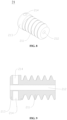
- the first-stage worm 21 includes a first toothed portion 211
- the second-stage worm 22 includes a second toothed portion 221
- the first toothed portion 211 and the transmission gear 23 form a transmission mesh structure.
- the second toothed portion 221 is located on one side, away from the first toothed portion 211, of the transmission gear 23, and the second toothed portion 221 may be located on one end, away from the first toothed portion 211, of the second-stage worm 22.
- the transmission assembly further includes an output gear 24, and the output gear 24 and the second toothed portion 221 form a transmission mesh structure.
- the transmission connection between the first component and the second component means that power can be transmitted between the first component and the second component, and the first component and the second component can be directly connected or connected through other transmission member.
- the first housing 11 further includes a first protruding portion 112 and a second protruding portion 113, both the first protruding portion 112 and the second protruding portion 113 extend from the bottom wall 111 toward the accommodating cavity 101, and the first protruding portion 112 and the second protruding portion 113 are in a position-limiting cooperation with the second-stage worm 22.
- the first protruding portion 112 is located on one side of the second toothed portion 221
- the second protruding portion 113 is located on another side of the second toothed portion 221.
- the first protruding portion 112 and the second protruding portion 113 are provided, and the first protruding portion 112 and the second protruding portion 113 are respectively arranged on two sides of the second toothed portion 221 of the second-stage worm 22, so as to support and limit the second-stage worm 22, thus reduce the axial shafting of the second-stage worm 22.
- the second housing 12 further includes a third protruding portion 122, and the third protruding portion 122 extends from the top wall 121 toward the accommodating cavity 101.
- the third protruding portion 122 is located between the second toothed portion 221 and the transmission gear 23 and the third protruding portion 122 is arranged close to the transmission gear 23, the third protruding portion 122 is in a position-limiting cooperation with the second-stage worm 22, and a distance between the third protruding portion 122 and the transmission gear 23 is within a preset range.
- a vertical force (a radial direction of the first-stage worm 21) is generated during the meshing operation between the transmission gear 23 and the first toothed portion 211, which is easy to cause the transmission gear 23 to move.
- the third protruding portion 122 is arranged close to the transmission gear 23, the third protruding portion 122 is in a position-limiting cooperation with the second-stage worm 22, and the distance between the third protruding portion 122 and the transmission gear 23 is within the preset range, so that the movement along the radial direction of the first-stage worm 21 during the operation of the transmission gear 23 and the first-stage worm 21 can be limited.
- the distance between the third protruding portion 122 and the transmission gear 23 can be set according to the needs of the user, as long as the movement of the transmission gear 23 toward the top wall 121 can be limited.
- the drive device 1000 according to the embodiment of the present application can be provided with three or more stages of worm drive.
- three or more stages of worm drive are provided, corresponding protruding portions can be provided to limit the worms.
- two-stage worm drive is taken as an example for description.
- the drive device 1000 further includes at least three mounting portions 13 which are located on an outer circumferential side of the housing, so as to realize the stable mounting of the drive device 1000.
- the at least three mounting portions 13 and the housing are integrally formed, an area of a rectangular region defined by the at least three mounting portions 13 and an outer surface of the housing is less than or equal to 9230 square millimeters, a transmission ratio of the transmission assembly is greater than or equal to 620 and less than or equal to 700, and an output torque of the transmission assembly ranges from 3N.m to 7N.m.
- the drive device 1000 includes a first mounting portion 131, a second mounting portion 132 and a third mounting portion 133 which are located on the outer circumferential side of the housing, the first mounting portion 131 and the second mounting portion 132 are located on two radial sides of the second-stage worm 22, and the third mounting portion 133 is located on one side, away from the first-stage worm 21, of the second-stage worm 22.
- the housing includes a first side wall 102, the first side wall 102 is located on one side of the housing, and the first-stage worm 21 and the second-stage worm 22 are located between the first side wall 102 and the third mounting portion 133 along the axial direction of the second-stage worm 22.
- a center distance a between a mounting hole of the first mounting portion 131 and a mounting hole of the second mounting portion 132 is less than 79mm along as radial direction of the second-stage worm 22, and a distance b between a mounting hole of the third mounting portion 133 and an outer surface of the first side wall 102 is less than 117mm along the axial direction of the second-stage worm 22.
- the second-stage worm 22 includes a first cylindrical portion 222 and a second cylindrical portion 223, the second toothed portion 221 is located between the first cylindrical portion 222 and the second cylindrical portion 223, and at least part of the second cylindrical portion 223 is located between the second toothed portion 221 and the transmission gear 23.
- the first protruding portion 112 includes a first groove portion 1120
- the second protruding portion 113 includes a second groove portion 1130
- the third protruding portion 122 includes a third groove portion 1220.
- At least part of the first cylindrical portion 222 is located in a groove cavity of the first groove portion 1120, and the first cylindrical portion 222 is in a clearance fit with the first groove portion 1120.
- the second cylindrical portion 223 a first sub-portion and a second sub-portion which are arranged axially, the first sub-portion is located between the second toothed portion 221 and the second sub-portion, at least part of the first sub-portion is located in a groove cavity of the second groove portion 1130, and the first sub-portion is in a clearance fit with the second groove portion 1130.
- At least part of the second sub-portion is located in a groove portion of the third groove portion 1220, and the second sub-portion is in a clearance fit with the third groove portion 1220.
- the first protruding portion 112, the second protruding portion 113 and the third protruding portion 122 cooperate with each other to support and limit the second-stage worm 22, so that the second-stage worm 22 rotates stably, thus reducing the noise during the rotation of the second-stage worm 22.
- the first groove portion 1120 includes a first abutting portion 1121 and a first oil groove 1122, the first cylindrical portion 222 abuts against the first abutting portion 1121, the first oil groove 1122 is recessed from part of a wall portion of the first abutting portion 1121, and the first oil groove 1122 is located at part of an outer circumferential side of the first cylindrical portion 222; and/or, the second groove portion 1130 includes a second abutting portion 1131 and a second oil groove 1132, the first sub-portion abuts against the second abutting portion 1131, the second oil groove 1132 is recessed from part of a wall portion of the second abutting portion 1131, and the second oil groove 1132 is located at part of an outer circumferential side of the first sub-portion; and/or, the third groove portion 1220 includes a third abutting portion 1121 and a first oil groove 1122, the first cylindrical portion 222 abuts against the first abutting portion 1121, the
- the second-stage worm 22 can have an excellent lubrication effect, which reduces the friction between the second-stage worm 22 and the protruding portions.
- the first groove portion 1120, the second groove portion 1130 and the third groove portion 1220 are respectively provided with corresponding oil grooves, so as to fully lubricate the second-stage worm 22.
- an axial length of second-stage worm 22 is larger than an axial length of the first-stage worm 21, and the axial length of the second-stage worm 22 is greater than or equal to 550mm and less than or equal to 650mm. Since the length of the second-stage worm 22 is relatively long, the strength of the second-stage worm 22 is arranged to be larger than the strength of the first-stage worm 21. Specifically, the first-stage worm 21 is made of plastic, and the second-stage worm 22 is made of metal. In an embodiment, the transmission gear 23 is made of plastic. By arranging the second-stage worm 22 to be made of metal, the second-stage worm 22 can be prevented from being broken due to long length when large torque is transmitted.
- the mass of the drive device 1000 can be better limited.
- the second-stage worm 22 can be made of high-strength plastic, as long as the strength of the second-stage worm 22 can be improved, and the material of the second-stage worm 22 is not limited herein.
- the first housing 11 further includes at least one fourth protruding portion 114, the fourth protruding portion 114 extends from the bottom wall 111 toward the accommodating cavity 101, and at least part of the fourth protruding portion 114 is located between the second protruding portion 113 and the third protruding portion 122 along the axial direction of the second-stage worm 22.
- the fourth protruding portion 114 includes a fourth groove portion 1140, the fourth groove portion 1140 includes a fourth abutting portion 1141, part of the second cylindrical portion 223 is located in a groove cavity of the fourth groove portion 1140 and is in a clearance fit with the fourth groove portion 1140, and the second cylindrical portion 223 abuts against the fourth abutting portion 1141.
- the structure of part of the fourth protruding portion 114 may be similar to the first protruding portion 112 and the second protruding portion 113, and a fourth oil groove may be defined in the fourth groove portion 1140, so as to lubricate the middle position of the second-stage worm 22.
- the oil groove may not be defined in the fourth protruding portion 114, so that the fourth protruding portion 114 can play a better supporting and limiting role and prevent the deformation of the second-stage worm 22 due to the long length.
- One, two, three or more protruding portions 114 can be provided.
- the second housing 12 includes at least one fifth protruding portion 123, the fifth protruding portion 123 includes a fifth groove portion 1230, the fifth groove portion 1230 includes a fifth abutting portion 1231, part of the second-stage worm 22 is located in a groove cavity of the fifth groove portion 1230 and abuts against the fifth abutting portion 1231, and the fifth protruding portion 123 is arranged adjacent to at least one of the first protruding portion 112, the second protruding portion 113 and the fourth protruding portion 114, so as to limit the movement of the second-stage worm 22 along a direction perpendicular to the bottom wall 111.
- the second housing 12 includes two fifth protruding portions 123 which are spaced apart along the axial direction of the second-stage worm 22, and the first protruding portion 112 and the second protruding portion 113 are located between the two fifth protruding portions 123, so that the first protruding portion 112, the second protruding portion 113, and the fifth protruding portions 123 cooperate with each other, so as to prevent the second-stage worm 22 from generating vertical shifting.
- the drive device 1000 further includes a conductive member 40 and a conductive member 50, and the motor 30 includes power supply terminals 32 which are exposed to an outer surface of the motor 31.
- the control member 50 includes power supply control terminals 51, the power supply terminal 32 is electrically connected with the power supply control terminal 51 through the conductive member 40, and part of the conductive member 40 is buried in the bottom wall 111.
- the conductive member 40 includes first electrical connection portions 41 and second electrical connection portions 41 which are electrically connected with each other, and the first electrical connection portions 41 and the second electrical connection portions 42 are rigid conductive portions.
- the power supply terminal 32 is welded to the first electrical connection portion 41, or the power supply terminal 32 is in a snap-fit connection with the first electrical connection portion 41.
- the power supply control terminal 51 is welded to the second electrical connection portion 42, or the power supply control terminal 51 is in a snap-fit connection with the second electrical connection portion 42.
- the above arrangement facilitates the automatic assembly of the first electrical connection portion 41 and the power supply terminal 32 of the motor 30, and the automatic assembly of the second electrical connection portion 42 and the power supply control terminal 51 of the control member 50.
- the conductive member 40 may be a flexible lead wire, which is not limited herein.
- the first electrical connection portion 41 is arranged close to the power supply terminal 32, and a distance between the first electrical connection portion 41 and the power supply terminal 32 is within a first preset range. At this time, the first electrical connection portion 41 is arranged close to the power supply terminal 32, and the distance between the first electrical connection portion 41 and the power supply terminal 32 is small, which can facilitate the automatic assembly of the first electrical connection portion 41 and the power supply terminal 32 and facilitate the electrical connection of the first electrical connection portion 41 and the power supply terminal 32 through soldering tin or snap-fit.
- the distance between the first electrical connection portion 41 and the power supply terminal 32 is within the first preset range, which means that the distance between the first electrical connection portion 41 and the power supply terminal 32 is less than or equal to a distance that the first electrical connection portion 41 and the power supply terminal 32 can be fixed by solder or be snapped.
- the specific size of the first preset range is not limited herein.
- the distance between the first electrical connection portion 41 and the power supply terminal 32 can be zero, so that the first electrical connection portion 41 is in contact with the power supply terminal 32, and then the first electrical connection portion 41 and the power supply terminal 32 are fixed and electrically connected by solder, or as shown in FIG. 12 , each first electrical connection portion 41 includes a clamping spring 411, which is in a snap-fit connection with the power supply terminal 32.
- the motor 30 includes a positive power supply terminal and a negative power supply terminal, and the output shaft 31 of the motor 30 is rotated by energizing the positive power supply terminal and the negative power supply terminal.
- two conductive members 40 are provided, one conductive member 40 is electrically connected with the positive power supply terminal, and the other conductive member 40 is electrically connected with the negative power supply terminal, so as to realize the stable transmission of electrical signals.
- the first housing 11 further includes a protruding structure, which extends from the bottom wall 111 toward the accommodating cavity 101, and part of the first electrical connection portion 41 and/or part of the second electrical connection 42 is buried in the protruding structure, so as to better secure and protect the first electrical connection portion 41 and/or the second electrical connection portion 42.
- the bottom wall 111 can be arranged to be made of plastic, and the at least part of the conductive member 40 is buried in the bottom wall 111 by injection molding, and the two conductive members 40 are spaced apart at a predetermined distance. At this time, the two adjacent conductive members 40 are spaced apart by the bottom wall 111 to achieve mutual insulation.
- the first-stage worm 21 includes a mounting passage 212 which extends through the first-stage worm 21 axially, the output shaft 31 of the motor 30 penetrates through the mounting passage 212 and protrudes from the mounting passage 212, and the output shaft 31 protruding from the mounting passage 212 can be supported by a supporting structure, so that the motor 30 can be supported stably during rotation, thus reducing the noise of the motor 30 during rotation.
- the drive device 1000 further includes at least two magnetic elements 61 and a Hall element 62, the Hall element 62 is arranged close to the at least two magnetic elements 61, and the at least two magnetic elements 61 are located on an outer circumferential side of the output shaft 31.
- the first-stage worm 21 further includes a third cylindrical portion 213, the third cylindrical portion 213 is located between the first toothed portion 211 and the motor 30, the third cylindrical portion 213 has at least two first hole passages 214, the at least two first hole passages 214 are uniformly distributed along a circumferential direction of the third cylindrical portion 213 and extend along a radial direction of the third cylindrical portion 213, and at least part of each magnetic element 61 is located in the corresponding first hole passage 214.
- the first hole passage 241 may be a blind hole, which is convenient to limit the mounting position of the magnetic element 61 and prevent the magnetic element 61 from damaging the output shaft 31 of the motor 30 during mounting.
- the drive device 1000 includes two magnetic elements 61, one of which is a south pole (S pole) and the other one of which is a north pole (N pole).
- S pole south pole
- N pole north pole
- the output shaft 31 of the motor 30 drives the two magnetic elements 61 to rotate
- the N pole and the S pole are alternately close to the Hall element 62, so that the Hall element 62 detects the magnetic change of the magnetic elements 61, and then transmits the detection signal to the control member to obtain the parameter information such as the rotational speed of the motor 30.
- the magnetic elements 61 are mounted on the first-stage worm 21, the output shaft 31 of the motor 30 rotates and drives the first-stage worm 21 to rotate when the motor 30 operates, and the magnetic elements 61 rotate with the first-stage worm 21.
- the Hall element 62 interacts with the magnetic elements 61.
- the Hall element 62 may be a Hall sensor, a position sensor or other position detector.
- the feedback signal of the Hall sensor is a Hall signal, and the feedback signal of the position sensor is a Hall signal.
- the Hall sensor is taken as an example for description.
- the magnetic elements 61 When the output shaft 31 drives the first-stage worm 21 to rotate, and the magnetic elements 61 rotate with the first stage worm 21, the magnetic elements 61 periodically pass through the Hall sensor, and the Hall sensor may generate a periodic feedback signal, that is, the feedback signal changes from low level to high level or from low level to high level.
- the stepping motor operates for one circle, the magnetic elements 61 rotate for one circle.
- the control member collects the above feedback signal and determines the operating state of the motor 30 based on the state of the feedback signal.
- the operating state of the motor 30 at least includes the normal operating state of the motor 30 and the locked state of the motor 30.
- a distance is defined between the Hall element 62 and an outer circumferential side of the magnetic elements 61, which prevents the magnetic elements 61 from interfering with the Hall element 62 and damaging the Hall element 62 during the rotation of the magnetic elements 61 with the output shaft 31 of the motor 30.
- the drive device 1000 further includes the magnetic element 61
- at least part of the magnetic element 61 is embedded into the first-stage worm 21.
- the first-stage worm 21 has a first hole passage 214, and at least part of the magnetic element 61 is located in the first hole passage 214.
- the first-stage worm 21 is made of plastic, the magnetic element 16, the first-stage worm 21 and the output shaft 31 of the motor 30 form an integral structure by injection molding. With the above arrangement, the magnetic element 61, the first-stage worm 21 and the output shaft 31 of the motor 30 can be firmly connected, so as to prevent the magnetic element 16 from falling off.
- the drive device 1000 can reduce the damage of the magnetic element 16.
- the first-stage worm 21 and the output shaft 31 of the motor 30 can also be fixedly arranged by injection molding, so that the concentricity of the first-stage worm 21 and the output shaft 31 of the motor 30 is improved, and the relatively large lateral force generated by the first-stage worm 21 during rotation is reduced, thereby improving the transmission efficiency of the first-stage worm 21.
- two magnetic elements 61 may be provided, and the two magnetic elements 61 have cylindrical structures.
- One magnetic element is the south pole (S pole) and the other magnetic element is the north pole (N pole).
- the two magnetic elements 61 are located on the outer circumferential side of the output shaft 31 and are uniformly arranged along the circumferential direction of the output shaft 31.
- the magnetic elements 61 extend along the radial direction of the output shaft 31.
- one magnetic element 61 may be provided, and the magnetic element 61 has a cylindrical structure, one axial end of the magnetic element 61 is the south pole, and the other axial end of the magnetic element 61 is the north pole.
- the magnetic element may have an annular structure, an axial end of the first-stage worm 21 has an annular groove, and part of the magnetic element is sleeved in the annular groove and is fixed to the first-stage worm 21 by injection molding.
- a method for manufacturing a drive device is further provided according to an embodiment of the present application, which includes the method for injecting the output shaft 31 of the motor 30, the first-stage worm 21 and the magnetic element 61 into an integral structure, as shown in FIG. 15 to FIG. 18 , and the method includes the following steps:
- the plastic material for manufacturing the first-stage worm 21 is filled into the injection mold, and the first-stage worm 21 is molded by injection molding.
- the molded first-stage worm 21 includes the first toothed portion 211 and the third cylindrical portion 213.
- the magnetic element 61 and the output shaft 31 of the motor 30 are firmly connected with the first-stage worm 21 by injection molding during the molding of the first-stage worm 21, and part of the magnetic element 61 is embedded into the third cylindrical portion 213.
- An axial direction of the magnetic element 61 is perpendicular to an axial direction of the third cylindrical portion 213, and at least part of the output shaft 31 of the motor 30 is inserted in the first-stage worm 21 and is coaxially arranged with the first-stage worm 21.
- the motor 30 can be energized to start, and the integral structure is screwed out of the injection mold by the rotation of the output shaft 31 of the motor 30.
- step S130 when the first-stage worm 21 is molded in the injection mold, a high-temperature environment may exist in the injection mold.
- the magnetic element 61 is magnetized after the integral structure of the first-stage worm 21, the motor 30 and the magnetic element 61 is separated from the injection mold, so as to improve the magnetism of the magnetic element 61 in the drive device 1000.
- the magnetized magnetic element 61 has a south pole and a north pole, so that the magnetic element 61 and the Hall element 62 cooperate with each other, and the Hall element 62 can accurately detect the magnetic change of the magnetic element 61, so as to improve the accuracy of detecting parameter information such as the rotational speed of the motor 30.
- one of the magnetic elements 61 can be magnetized to be the south pole, and the other magnetic element 61 can be magnetized to be the north pole.
- FIG. 17 when the magnetic element has a cylindrical structure and one magnetic element is provided, one axial end of the magnetic element is magnetized to be the south pole, and the other axial end is magnetized to be the north pole.
- the transmission assembly further includes an output gear 24, the output shaft 24 and the second toothed portion 221 of the second-stage worm 22 form a transmission mesh structure, and the output gear 24 is made of plastic.
- the transmission assembly of the drive device 1000 includes the first-stage worm 21 and the second-stage worm 22, the first-stage worm 21 is in transmission connection with the output shaft 31 of the motor 30, and the second-stage worm 22 is in transmission connection with the first-stage worm 21.
- the output gear of the transmission assembly has a smaller size by providing two stage worm drive according to the embodiment of the present application, so that the structure of the drive device 1000 is compact.
- the first housing 11 of the drive device 1000 includes the first protruding portion 112 and the second protruding portion 113, the first protruding portion 112 and the second protruding portion 113 are arranged on two sides of the second toothed portion 221 of the second-stage worm 22, so as to support and limit the second-stage worm 22.
- the second housing 12 includes the third protruding portion 122, the third protruding portion 122 is arranged close to the transmission gear 23, and the distance between the third protruding portion 122 and the transmission gear 23 is within the preset range, which can limit the movement along the radial direction of the worm caused by the meshing operation of the transmission gear 23 and the first-stage worm 21, so that the drive device can stably drive the valve core of the control valve to rotate and improve the drive performance of the drive device 1000.
- a control valve is further provided according to an embodiment of the present application, which includes a valve core and the drive device 1000 according to any one of above embodiments, the transmission assembly of the drive device 1000 further includes an output gear 24, the valve core includes an input shaft section, and the input shaft section is in a transmission cooperation with the output gear 24, so that the input shaft section and the output gear 24 rotate synchronously.
- an output shaft of the output gear 24 may include a square shaft hole, and an outer surface of the input shaft section of the valve core is a square shaft section that fits the square shaft hole. The square shaft section is inserted in the square shaft hole, so as to realize the rotation of the valve core driven by the output gear 24.
- an output shaft of the output gear 24 may include a square shaft section
- the input shaft section of the valve core may include a square shaft hole.
- the square shaft section is inserted in the square shaft hole, so as to realize the rotation of the valve core driven by the output gear 24.
Landscapes
- Engineering & Computer Science (AREA)
- General Engineering & Computer Science (AREA)
- Mechanical Engineering (AREA)
- Gear Transmission (AREA)
- Connection Of Motors, Electrical Generators, Mechanical Devices, And The Like (AREA)
- Electrically Driven Valve-Operating Means (AREA)
Applications Claiming Priority (3)
| Application Number | Priority Date | Filing Date | Title |
|---|---|---|---|
| CN202110064095 | 2021-01-18 | ||
| CN202110138021.XA CN114811146A (zh) | 2021-01-18 | 2021-02-01 | 驱动装置和控制阀 |
| PCT/CN2022/072435 WO2022152306A1 (zh) | 2021-01-18 | 2022-01-18 | 驱动装置、控制阀和驱动装置的制造方法 |
Publications (2)
| Publication Number | Publication Date |
|---|---|
| EP4279780A1 true EP4279780A1 (de) | 2023-11-22 |
| EP4279780A4 EP4279780A4 (de) | 2024-12-18 |
Family
ID=82446946
Family Applications (1)
| Application Number | Title | Priority Date | Filing Date |
|---|---|---|---|
| EP22739181.0A Pending EP4279780A4 (de) | 2021-01-18 | 2022-01-18 | Antriebsvorrichtung, steuerventil und verfahren zur herstellung einer antriebsvorrichtung |
Country Status (4)
| Country | Link |
|---|---|
| US (1) | US12209680B2 (de) |
| EP (1) | EP4279780A4 (de) |
| JP (1) | JP7577221B2 (de) |
| WO (1) | WO2022152306A1 (de) |
Families Citing this family (1)
| Publication number | Priority date | Publication date | Assignee | Title |
|---|---|---|---|---|
| NL2030921B9 (en) * | 2022-02-14 | 2023-09-27 | Mci Mirror Controls Int Netherlands B V | Adjustment mechanism and adjustment device comprising such adjustment mechanism |
Family Cites Families (13)
| Publication number | Priority date | Publication date | Assignee | Title |
|---|---|---|---|---|
| US4158483A (en) * | 1975-07-09 | 1979-06-19 | Harman International Industries, Inc. | Remote controlled rearview mirror |
| CN101806332A (zh) | 2010-04-07 | 2010-08-18 | 孙效 | 双蜗轮蜗杆减速机 |
| JP2016109266A (ja) | 2014-12-10 | 2016-06-20 | ミネベア株式会社 | アクチュエータ |
| DE102015104111A1 (de) * | 2015-03-19 | 2016-09-22 | Witte Automotive Gmbh | Antriebsmechanismus mit Doppelschneckengetriebe |
| JP6599651B2 (ja) | 2015-06-11 | 2019-10-30 | 株式会社不二工機 | ロータリー弁 |
| JP6539776B2 (ja) * | 2015-08-21 | 2019-07-03 | シュクラ ゲレーテバォ ゲーエムベーハーSchukra Geraetebau Gmbh | シート・コンポーネント調節アクチュエータ、車両シート、および、シート・コンポーネントを調節する方法 |
| KR101746829B1 (ko) * | 2015-10-01 | 2017-06-14 | 박미리 | 감속기 |
| US10479399B2 (en) * | 2017-06-02 | 2019-11-19 | Steering Solutions Ip Holding Corporation | Redundant gear assembly for vehicle steering column and method |
| CN108591445A (zh) | 2018-02-11 | 2018-09-28 | 上海众持汽车零部件有限公司 | 一种新能源汽车用换档执行器 |
| CN108331960A (zh) | 2018-03-27 | 2018-07-27 | 厦门三登塑胶工业有限公司 | 用在阀的塑钢组合手动涡轮蜗杆机构 |
| CN111219492B (zh) | 2018-11-23 | 2022-04-05 | 盾安环境技术有限公司 | 电子阀 |
| CN112212055A (zh) | 2019-07-10 | 2021-01-12 | 盾安环境技术有限公司 | 执行器 |
| JP6742489B2 (ja) | 2019-08-28 | 2020-08-19 | 日立オートモティブシステムズ株式会社 | 弁 |
-
2022
- 2022-01-18 WO PCT/CN2022/072435 patent/WO2022152306A1/zh not_active Ceased
- 2022-01-18 JP JP2023543213A patent/JP7577221B2/ja active Active
- 2022-01-18 EP EP22739181.0A patent/EP4279780A4/de active Pending
- 2022-01-18 US US18/272,867 patent/US12209680B2/en active Active
Also Published As
| Publication number | Publication date |
|---|---|
| EP4279780A4 (de) | 2024-12-18 |
| WO2022152306A1 (zh) | 2022-07-21 |
| US12209680B2 (en) | 2025-01-28 |
| JP7577221B2 (ja) | 2024-11-01 |
| JP2024504129A (ja) | 2024-01-30 |
| US20240084913A1 (en) | 2024-03-14 |
Similar Documents
| Publication | Publication Date | Title |
|---|---|---|
| KR102644987B1 (ko) | Bldc 모터를 구비한 액추에이터용 구동장치 | |
| EP2023467A1 (de) | Motor mit reduktionsgetriebe und herstellungsverfahren dafür | |
| KR102723294B1 (ko) | 전기 볼 밸브 및 전기 밸브 제조 방법 | |
| US20240063689A1 (en) | Deceleration mechanism and motor having deceleration mechanism installed therein | |
| EP4279780A1 (de) | Antriebsvorrichtung, steuerventil und verfahren zur herstellung einer antriebsvorrichtung | |
| EP3293415A1 (de) | Innenzahnkranz, antriebsanordnung und anwendungsvorrichtung | |
| JP5505683B2 (ja) | 電動ポンプ | |
| CN206311059U (zh) | 小回程差角度传感器及其行星齿轮 | |
| CN213479112U (zh) | 电动致动器 | |
| CN113833896B (zh) | 电动球阀 | |
| CN114811146A (zh) | 驱动装置和控制阀 | |
| KR20210016151A (ko) | Sbw 구동 액추에이터 | |
| CN211748676U (zh) | 电动窗帘牵引装置 | |
| CN214756024U (zh) | 一种后固定轴式直线步进电机 | |
| CN221467498U (zh) | 一种推杆电机 | |
| JP7823062B2 (ja) | 駆動装置及びバルブ | |
| CN217789490U (zh) | 驱动装置 | |
| KR20240079848A (ko) | 시프트 바이 와이어용 액츄에이터 | |
| CN223821923U (zh) | 电控牙盘结构及自行车 | |
| CN219994516U (zh) | 一种高精度电子水阀结构 | |
| CN212785045U (zh) | 变速电机 | |
| CN213279427U (zh) | 电动致动器 | |
| CN213279428U (zh) | 电动致动器 | |
| WO2022030451A1 (ja) | 回転式アクチュエータ | |
| CN115596879A (zh) | 液压阀驱动器及液压阀 |
Legal Events
| Date | Code | Title | Description |
|---|---|---|---|
| STAA | Information on the status of an ep patent application or granted ep patent |
Free format text: STATUS: THE INTERNATIONAL PUBLICATION HAS BEEN MADE |
|
| PUAI | Public reference made under article 153(3) epc to a published international application that has entered the european phase |
Free format text: ORIGINAL CODE: 0009012 |
|
| STAA | Information on the status of an ep patent application or granted ep patent |
Free format text: STATUS: REQUEST FOR EXAMINATION WAS MADE |
|
| 17P | Request for examination filed |
Effective date: 20230803 |
|
| AK | Designated contracting states |
Kind code of ref document: A1 Designated state(s): AL AT BE BG CH CY CZ DE DK EE ES FI FR GB GR HR HU IE IS IT LI LT LU LV MC MK MT NL NO PL PT RO RS SE SI SK SM TR |
|
| DAV | Request for validation of the european patent (deleted) | ||
| DAX | Request for extension of the european patent (deleted) | ||
| A4 | Supplementary search report drawn up and despatched |
Effective date: 20241114 |
|
| RIC1 | Information provided on ipc code assigned before grant |
Ipc: F16H 57/04 20100101ALN20241108BHEP Ipc: F16H 57/021 20120101ALN20241108BHEP Ipc: F16H 1/22 20060101ALI20241108BHEP Ipc: F16H 57/039 20120101ALI20241108BHEP Ipc: F16K 31/53 20060101ALI20241108BHEP Ipc: F16K 31/04 20060101AFI20241108BHEP |
|
| STAA | Information on the status of an ep patent application or granted ep patent |
Free format text: STATUS: EXAMINATION IS IN PROGRESS |
|
| 17Q | First examination report despatched |
Effective date: 20250903 |