EP4279877B1 - Dispositif de mesure pour mesurer une grandeur physique dans une unité contenant un milieu - Google Patents
Dispositif de mesure pour mesurer une grandeur physique dans une unité contenant un milieu Download PDFInfo
- Publication number
- EP4279877B1 EP4279877B1 EP23160867.0A EP23160867A EP4279877B1 EP 4279877 B1 EP4279877 B1 EP 4279877B1 EP 23160867 A EP23160867 A EP 23160867A EP 4279877 B1 EP4279877 B1 EP 4279877B1
- Authority
- EP
- European Patent Office
- Prior art keywords
- measuring device
- opening
- housing
- section
- plug connection
- Prior art date
- Legal status (The legal status is an assumption and is not a legal conclusion. Google has not performed a legal analysis and makes no representation as to the accuracy of the status listed.)
- Active
Links
Images


Classifications
-
- G—PHYSICS
- G01—MEASURING; TESTING
- G01D—MEASURING NOT SPECIALLY ADAPTED FOR A SPECIFIC VARIABLE; ARRANGEMENTS FOR MEASURING TWO OR MORE VARIABLES NOT COVERED IN A SINGLE OTHER SUBCLASS; TARIFF METERING APPARATUS; MEASURING OR TESTING NOT OTHERWISE PROVIDED FOR
- G01D21/00—Measuring or testing not otherwise provided for
- G01D21/02—Measuring two or more variables by means not covered by a single other subclass
-
- G—PHYSICS
- G01—MEASURING; TESTING
- G01D—MEASURING NOT SPECIALLY ADAPTED FOR A SPECIFIC VARIABLE; ARRANGEMENTS FOR MEASURING TWO OR MORE VARIABLES NOT COVERED IN A SINGLE OTHER SUBCLASS; TARIFF METERING APPARATUS; MEASURING OR TESTING NOT OTHERWISE PROVIDED FOR
- G01D11/00—Component parts of measuring arrangements not specially adapted for a specific variable
- G01D11/24—Housings ; Casings for instruments
- G01D11/245—Housings for sensors
-
- G—PHYSICS
- G01—MEASURING; TESTING
- G01D—MEASURING NOT SPECIALLY ADAPTED FOR A SPECIFIC VARIABLE; ARRANGEMENTS FOR MEASURING TWO OR MORE VARIABLES NOT COVERED IN A SINGLE OTHER SUBCLASS; TARIFF METERING APPARATUS; MEASURING OR TESTING NOT OTHERWISE PROVIDED FOR
- G01D11/00—Component parts of measuring arrangements not specially adapted for a specific variable
- G01D11/30—Supports specially adapted for an instrument; Supports specially adapted for a set of instruments
-
- H—ELECTRICITY
- H01—ELECTRIC ELEMENTS
- H01R—ELECTRICALLY-CONDUCTIVE CONNECTIONS; STRUCTURAL ASSOCIATIONS OF A PLURALITY OF MUTUALLY-INSULATED ELECTRICAL CONNECTING ELEMENTS; COUPLING DEVICES; CURRENT COLLECTORS
- H01R13/00—Details of coupling devices of the kinds covered by groups H01R12/70 or H01R24/00 - H01R33/00
- H01R13/46—Bases; Cases
- H01R13/52—Dustproof, splashproof, drip-proof, waterproof, or flameproof cases
- H01R13/5219—Sealing means between coupling parts, e.g. interfacial seal
-
- H—ELECTRICITY
- H01—ELECTRIC ELEMENTS
- H01R—ELECTRICALLY-CONDUCTIVE CONNECTIONS; STRUCTURAL ASSOCIATIONS OF A PLURALITY OF MUTUALLY-INSULATED ELECTRICAL CONNECTING ELEMENTS; COUPLING DEVICES; CURRENT COLLECTORS
- H01R13/00—Details of coupling devices of the kinds covered by groups H01R12/70 or H01R24/00 - H01R33/00
- H01R13/66—Structural association with built-in electrical component
- H01R13/665—Structural association with built-in electrical component with built-in electronic circuit
- H01R13/6683—Structural association with built-in electrical component with built-in electronic circuit with built-in sensor
-
- H—ELECTRICITY
- H01—ELECTRIC ELEMENTS
- H01R—ELECTRICALLY-CONDUCTIVE CONNECTIONS; STRUCTURAL ASSOCIATIONS OF A PLURALITY OF MUTUALLY-INSULATED ELECTRICAL CONNECTING ELEMENTS; COUPLING DEVICES; CURRENT COLLECTORS
- H01R13/00—Details of coupling devices of the kinds covered by groups H01R12/70 or H01R24/00 - H01R33/00
- H01R13/73—Means for mounting coupling parts to apparatus or structures, e.g. to a wall
- H01R13/74—Means for mounting coupling parts in openings of a panel
- H01R13/746—Means for mounting coupling parts in openings of a panel using a screw ring
-
- H—ELECTRICITY
- H01—ELECTRIC ELEMENTS
- H01R—ELECTRICALLY-CONDUCTIVE CONNECTIONS; STRUCTURAL ASSOCIATIONS OF A PLURALITY OF MUTUALLY-INSULATED ELECTRICAL CONNECTING ELEMENTS; COUPLING DEVICES; CURRENT COLLECTORS
- H01R13/00—Details of coupling devices of the kinds covered by groups H01R12/70 or H01R24/00 - H01R33/00
- H01R13/73—Means for mounting coupling parts to apparatus or structures, e.g. to a wall
- H01R13/74—Means for mounting coupling parts in openings of a panel
- H01R13/748—Means for mounting coupling parts in openings of a panel using one or more screws
Definitions
- the present invention relates to a measuring device for measuring a physical quantity, such as a pressure, a temperature or a fill level, in a unit containing a medium according to claim 1.
- the sensors used are each used to measure a physical quantity in the unit, which can be, for example, a pressure, a temperature or a level of a medium contained in the unit.
- sensors can be specified by guidelines or standards that must be observed when designing the use of sensors. For example, with a sensor housing with a sealing class of IP67 or IP69, the housing must be protected against the ingress of foreign bodies, i.e. the housing must be dust-tight and keep out water for a specific, short period of time.
- pressure equalization elements which usually consist of a membrane that is permeable to air and water vapor on the one hand, but water and oil repellent on the other, and a mechanical connection between the interior of the housing and the surroundings of the housing.
- labyrinth is also provided as a mechanical connection between the membrane and the environment, whereby the labyrinth protects the membrane from strong water jets.
- labyrinth means that the mechanical connection is not linear, but with at least one curve, so that the membrane is not visible from the outside and therefore has no direct connection with the environment.
- pressure compensation elements with a labyrinth that are available on the market are more expensive to purchase than pressure compensation elements that only consist of a membrane.
- Pressure compensation elements with a labyrinth require more space on the housing than pressure compensation elements without a labyrinth, which makes the housing larger and therefore more expensive.
- the housing To attach the pressure compensation element with labyrinth to the housing, the housing must be additionally pre-treated, such as by providing it with a through hole and a thread, which results in additional costs.
- the membrane For pressure compensation elements without labyrinth, the membrane is glued to the inside of the housing and only an opening or through hole is provided in the housing. However, this does not protect the membrane from water jets.
- EN 10 2012 201018 A1 discloses a known pressure measuring device with a process connection and a plug connection in a measuring housing, wherein a channel for pressure equalization between the housing interior and the environment is arranged in the plug connection
- the invention is based on the object of improving a measuring device for measuring a physical quantity as mentioned above in such a way that it can be produced inexpensively and easily.
- the object is achieved according to the invention by a measuring device for measuring a physical quantity in a unit containing a medium with the features of claim 1.
- the plug connection consists of an outer section for connecting the plug and the fastening section, wherein the electrical plug contacts are provided within the outer section and electrical lines are led from the electrical plug contacts through the fastening section into the interior of the housing.
- the second opening in the wall is designed to fit the shape of the inner section so that the inner section can be inserted into the housing through the second opening until the flange element rests against the wall. Due to the flattened outer side of the inner section, the second opening can be provided closer to the first opening so that a more compact arrangement of the plug connection on the first opening or on the membrane is possible.
- a side of the flange element facing the wall has a second groove which is circular or spiral-shaped.
- the at least one outlet bore is aligned coaxially or radially to a plug connection axis of the plug connection.
- the second groove is designed to provide a connection between the first opening of the wall and the coaxially or radially directed outlet bore in order to allow pressure equalization in the housing.
- a diameter of the first opening is many times smaller than a diameter of the second opening. This makes it possible to further simplify and reduce the cost of producing the measuring device with a predetermined leak protection class.
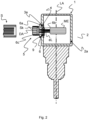
- FIG. 1 is a schematic perspective view of a preferred embodiment of a measuring device 1 according to the invention for measuring a physical quantity in a unit (not shown) containing a medium.
- the physical quantity can be, for example, a pressure, a temperature or a fill level of the medium in the unit.
- the unit (not shown) can be, for example, a container, a pipeline or the like.
- a first opening 3a in particular in the form of a through hole, is provided in the wall 2a of the housing 2, the first opening 3a being covered on an inner side of the housing 2 by means of a membrane 4.
- the membrane 4 is preferably permeable to air and water vapor, but water, dust and oil repellent, so that pressure equalization of the interior of the housing 2 with the environment is possible in order to avoid pumping effects.
- the wall 2a can have a cylindrical or square cross-sectional shape.
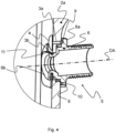
- Figure 2 shows a schematic sectional view of the measuring device 1 along a longitudinal axis LA of the measuring device 1 together with a partial view of the plug S.
- the plug connection 5 is provided adjacent to the membrane 4 on the wall 2a of the housing 2 and is formed with a fastening section 6 for fastening the plug connection 5 to the wall 2a of the housing 2.
- the fastening section 6 has a flange element 6a, wherein the flange element 6a is arranged on an outer side of the wall 2a of the housing 2.
- the flange element 6a is designed to cover the first opening 3a and to have at least one outlet bore 9 which is connected to the first opening 3a. This means that the flange element 6a of the plug connection 5, with its at least one outlet bore 9, enables pressure equalization between the housing interior and the environment, so that a channel for pressure equalization is integrated into the plug connection 5.
- the flange element 6a has a circular shape with such a large diameter that the first opening 3a is covered on the outside.
- the plug connection 5 has in particular an inner section 6b connected to the flange element 6a, wherein the inner section 6b can be inserted into a second opening 3b and comprises a hollow cylindrical shape with a flattened outer side 11.
- the flattened outer side 11 of the inner section 6b faces the membrane 4.
- the flattened outer side of the inner section 6b prevents the plug connection 5 from twisting relative to the housing 2.
- the special shape of the inner section 6b serves on the one hand to align and on the other hand to prevent the plug connection 5 from twisting relative to the second opening 3b or the housing 2.
- the plug connection 5 additionally consists of an outer section 6c for connecting the plug S.
- the electrical plug contacts Sk are provided within the outer section 6c. Electrical lines eL are led from the electrical plug contacts Sk through the fastening section 6 into the interior of the housing 2 in a gas-tight manner, so that the electrical plug contacts Sk are connected to the measuring electronics ME.
- the outer portion 6c of the plug connection 5 is preferably formed with an external thread so that the plug S can be connected to the plug connection 5 by screwing it onto the outer portion 6c.
- the second opening 3b in the wall 2a is advantageously designed to conform to the shape of the inner section 6b, so that the inner section 6b can be inserted into the housing 2 with a precise fit through the second opening 3b until the flange element 6a rests against the wall 2a.
- the form-fitting design of the inner section 6b and the second opening 3b simplifies the assembly of the plug connection 5 to the housing 2 and enables the flange element 6a to be precisely aligned with the first opening 3a.
- the second opening 3b can be arranged closer to the membrane 4 or to the first opening 3a by forming the first opening 3a in the area of the flattened outer side 11 of the inner section 6b, so that the entire design of the plug connection 5 can be more compact.
- the flange element 6a has a circular shape having a larger cross section than a cross section of the inner portion 6b, so that the first opening 3a is covered on one side by the flange element 6a.
- a first groove 8 is provided, into which a retaining clip 7, such as a clamping spring or a locking ring, can be inserted.
- the retaining clip 7 is arranged between the end of the inner section 6b and the wall 2, whereby the plug connection 5 is clamped to the housing 2 between the flange element 6a and the retaining clip 7.
- An open area of the approximately U-shaped retaining clip 7 is directed in the direction of the first opening 3a, so that covering of the first opening 3a or the membrane 4 on the inside of the housing 2 is prevented. This also ensures that the first opening 3a is only covered on the outside by the flange element 6a of the plug connection 5.
- the approximate U-shape of the retaining clip 7 can serve as a centering aid when attaching the membrane 4, since the open area of the retaining clip 7 is directed towards the first opening 3a. This can make the assembly work easier.
- the first opening 3a on the outside of the wall 2c is completely covered by the flange element 6a of the fastening section 6 of the plug connection 5.
- the first opening 3a on the inside of the wall 2c is only covered by the membrane 4.
- a side of the flange element 6a facing the wall 2 has a second groove 9 which is circular or spiral-shaped in the flange element 6a.
- the at least one outlet bore 10 is aligned axially parallel to a plug connection axis DA of the plug connection 5.
- the at least one outlet bore 10 can preferably also be formed radially to the plug connection axis DA of the plug connection 5 on the flange element 6a.
- the second groove 9 is designed to provide a connection between the first opening 3a of the wall 2 and the axially parallel outlet bore 10.
- the second groove 9 preferably completely covers the first opening 3a at one end of the second groove 9 and opens into the outlet bore 10 at the other end of the second groove 9.
- the plug connection 5 thus includes the functionality of a labyrinth.
- the membrane 4 Since the measuring device 1 has to be cleaned by means of a high-pressure cleaner in certain applications, the membrane 4 is protected from destruction by the labyrinth against direct exposure to water jets.
- the integration of the labyrinth and pressure compensation function into the plug connection 5 enables a more compact design of the housing 2 of the measuring device 1, since no additional large installation space is required for the integration of a separate pressure compensation element with labyrinth.
Landscapes
- Physics & Mathematics (AREA)
- General Physics & Mathematics (AREA)
- Engineering & Computer Science (AREA)
- Microelectronics & Electronic Packaging (AREA)
- Measuring Fluid Pressure (AREA)
Claims (11)
- Dispositif de mesure (1) pour mesurer une grandeur physique dans une unité contenant un milieu, comprenant :un boîtier (2) qui comprend une paroi (2a) pour loger une électronique de mesure (ME) et une partie de connexion (2b) pour connecter le dispositif de mesure (1) à l'unité ;une membrane (4) prévue sur la paroi (2a) pour couvrir une première ouverture (3a) dans la paroi (2a),un connecteur enfichable (5) prévu sur la paroi (2a) adjacente à la membrane (4) et configuré pour fournir une connexion électrique entre l'électronique de mesure (ME) et des contacts électriques de connecteur (Sk) pour un connecteur (S) pouvant être connecté au dispositif de mesure (1) ;une deuxième ouverture (3b) dans laquelle le connecteur enfichable (5) peut être enfiché,dans lequel le connecteur enfichable (5) est disposé d'une partie de fixation (6) pour fixer le connecteur enfichable (5) à la paroi (2a) du boîtier (2) et la partie de fixation (6) comprend un élément de bride (6a), dans lequel l'élément de bride (6a) est disposé sur un côté extérieur de la paroi (2a) et l'élément de bride (6a) est configuré pour couvrir la première ouverture (3a) et pour comporter au moins un trou de forage de sortie (10) communiquant avec la première ouverture (3a).
- Dispositif de mesure (1) selon la revendication 1, dans lequel le connecteur enfichable (5) consiste d'une partie extérieure (6c) pour connecter le connecteur (S) et la partie de fixation (6), et dans lequel les contacts électriques de connecteur (Sk) sont prévus à l'intérieur de la partie extérieure (6c) et les lignes électriques (eL) sont guidées des contacts électriques de connecteur (Sk) à travers la partie de fixation (6) à l'intérieur du boîtier (2).
- Dispositif de mesure (1) selon la revendication 1 ou 2, dans lequel le connecteur enfichable (5) comprend une partie intérieure (6b) reliée à l'élément de bride (6a), dans lequel la partie intérieure (6b) peut être enfiché dans la deuxième ouverture (3b) et comporte une forme cylindrique creuse avec une face extérieure aplatie (11).
- Dispositif de mesure (1) selon la revendication 3, dans lequel la face aplatie de la partie intérieure (6b) est orientée vers la membrane (4).
- Dispositif de mesure (1) selon la revendication 3 ou 4, dans lequel la deuxième ouverture (3b) dans la paroi (2a) est configuré à forme finale par rapport à la forme de la section intérieure (6b), de sorte que la partie intérieure (6b) peut être enfichée dans le boîtier (2) avec un ajustement exact à travers la deuxième ouverture (3b) jusqu'à un contact du premier élément de la bride (6a) avec la paroi (2a).
- Dispositif de mesure (1) selon l'une des revendications 3 à 5, dans lequel l'élément de bride (6a) comprend une forme circulaire dont la section transversale est supérieure à une section transversale de la partie intérieure (6b), de sorte que la première ouverture (3a) est recouverte extérieurement par l'élément de bride (6a).
- Dispositif de mesure (1) selon l'une des revendications 3 à 6, dans lequel une pince de maintien (7) est enfichable dans une première rainure (8) prévue dans la partie intérieure (6b) pour serrer le connecteur enfichable (5) contre le boîtier (2).
- Dispositif de mesure (1) selon l'une des revendications précédentes, dans lequel un côté de l'élément de bride (6a) orienté vers la paroi (2a) comprend une deuxième rainure (9) qui est de forme circulaire ou spiroïdal.
- Dispositif de mesure (1) selon l'une des revendications précédentes, dans lequel ledit au moins un trou de forage de sortie (10) est orienté coaxialement ou radialement par rapport à un axe du connecteur enfichable (DA) du connecteur enfichable (5).
- Dispositif de mesure (1) selon la revendication 9, dans lequel la deuxième rainure (9) est configurée pour fournir une communication entre la première ouverture (3a) et le trou de forage de sortie (10) afin de permettre un équilibrage de pression dans le boîtier (2).
- Dispositif de mesure (1) selon l'une des revendications précédentes, dans lequel un diamètre de la première ouverture (3a) est plusieurs fois inférieur à un diamètre de la deuxième ouverture (3b).
Applications Claiming Priority (1)
| Application Number | Priority Date | Filing Date | Title |
|---|---|---|---|
| DE102022112227.1A DE102022112227A1 (de) | 2022-05-16 | 2022-05-16 | Messvorrichtung zum Messen einer physikalischen Größe in einer ein Medium enthaltenden Einheit |
Publications (3)
| Publication Number | Publication Date |
|---|---|
| EP4279877A1 EP4279877A1 (fr) | 2023-11-22 |
| EP4279877C0 EP4279877C0 (fr) | 2024-08-28 |
| EP4279877B1 true EP4279877B1 (fr) | 2024-08-28 |
Family
ID=88405081
Family Applications (1)
| Application Number | Title | Priority Date | Filing Date |
|---|---|---|---|
| EP23160867.0A Active EP4279877B1 (fr) | 2022-05-16 | 2023-03-09 | Dispositif de mesure pour mesurer une grandeur physique dans une unité contenant un milieu |
Country Status (4)
| Country | Link |
|---|---|
| US (1) | US12270683B2 (fr) |
| EP (1) | EP4279877B1 (fr) |
| CN (1) | CN117073745A (fr) |
| DE (1) | DE102022112227A1 (fr) |
Family Cites Families (14)
| Publication number | Priority date | Publication date | Assignee | Title |
|---|---|---|---|---|
| DE3635165A1 (de) * | 1986-10-16 | 1988-04-21 | Wabco Westinghouse Fahrzeug | Gehaeuseeinrichtung mit druckausgleich |
| DE4140487A1 (de) | 1991-12-09 | 1993-06-17 | Bosch Gmbh Robert | Steckerleiste |
| US6425692B1 (en) * | 1997-10-23 | 2002-07-30 | Fujikura, Ltd. | Connecting structure for optical connector |
| DE10127485A1 (de) | 2001-06-07 | 2002-12-12 | Wabco Gmbh & Co Ohg | Steckvorrichtung für ein Elektronikgehäuse |
| DE102007024472A1 (de) * | 2007-05-25 | 2008-11-27 | Volkswagen Ag | Getriebegehäuse für eine elektrische Antriebseinheit eines Scheibenwischers mit einer Entlüftungseinrichtung |
| DE102009019082B4 (de) * | 2009-04-22 | 2012-10-11 | Bimed Teknik A.S. | Steckverbindersystem für Außenanwendungen |
| JP2013011556A (ja) * | 2011-06-30 | 2013-01-17 | Md Innovations Kk | 隔膜気圧計 |
| DE102012201018B4 (de) * | 2012-01-24 | 2016-03-31 | Ifm Electronic Gmbh | Messgerät mit am Gehäuse vorgesehenem Luftdurchgang |
| DE102013208537A1 (de) * | 2012-12-27 | 2014-07-03 | Robert Bosch Gmbh | Drucksensoranordnung sowie Verfahren zum Montieren einer Drucksensoranordnung |
| DE102015103551A1 (de) * | 2015-03-11 | 2016-09-15 | Sick Ag | Steckerbaugruppe für einen Sensor und Verfahren zur Montage einer Steckerbaugruppe für einen Sensor |
| DE102016205117B4 (de) * | 2015-04-30 | 2025-11-27 | Valeo Eautomotive Germany Gmbh | Steckverbindung, elektrische Maschine und Fahrzeug |
| DE102018117454B3 (de) | 2018-07-19 | 2019-09-26 | Eugen Forschner Gmbh | Vorrichtung zur Durchführung eines elektrischen Leiters durch eine Wand |
| DE102019104728A1 (de) * | 2019-02-25 | 2020-08-27 | Nidec Gpm Gmbh | Pumpeinheit aufweisend einen Steckverbinder mit Druckausgleichselement |
| US11428596B2 (en) * | 2020-09-16 | 2022-08-30 | Wisenstech Ltd. | Vacuum gauge with an extended dynamic measurement range |
-
2022
- 2022-05-16 DE DE102022112227.1A patent/DE102022112227A1/de active Pending
-
2023
- 2023-03-09 EP EP23160867.0A patent/EP4279877B1/fr active Active
- 2023-03-28 CN CN202310313965.5A patent/CN117073745A/zh active Pending
- 2023-04-17 US US18/135,384 patent/US12270683B2/en active Active
Also Published As
| Publication number | Publication date |
|---|---|
| US12270683B2 (en) | 2025-04-08 |
| EP4279877C0 (fr) | 2024-08-28 |
| US20230366704A1 (en) | 2023-11-16 |
| CN117073745A (zh) | 2023-11-17 |
| DE102022112227A1 (de) | 2023-11-16 |
| EP4279877A1 (fr) | 2023-11-22 |
Similar Documents
| Publication | Publication Date | Title |
|---|---|---|
| EP2382693B1 (fr) | Dispositif de fixation pour fixer un câble sur un passage de boîtier | |
| EP1942325B1 (fr) | Dispositif d'étanchéité pour la fermeture d'un boîtier cellulaire de mesure de pression et ensemble cellulaire de mesure de pression muni de ce dispositif | |
| EP1698877B1 (fr) | Dispositif capteur de pression différentielle et capteur de pression différentielle associé | |
| EP4279877B1 (fr) | Dispositif de mesure pour mesurer une grandeur physique dans une unité contenant un milieu | |
| DE102014113924A1 (de) | Fahrzeugklimaanlagenmoduldichtung und Baugruppe mit einer Fahrzeugklimaanlagenmoduldichtung | |
| DE102016210682A1 (de) | Drucksensor | |
| DE102013216465A1 (de) | Leiterdichtungs-Anordnung und Kühlerlüftermodul | |
| EP3715795A1 (fr) | Détermination de la position dans un espace haute pression | |
| DE202022102688U1 (de) | Messvorrichtung zum Messen einer physikalischen Größe in einer ein Medium enthaltenden Einheit | |
| EP1538427B1 (fr) | Elément à ressort de compression pour connexion d'un câble à un transducteur | |
| EP2589272B1 (fr) | Ensemble et appareil doté d'un ensemble pour ventiler une zone compartiment | |
| EP4341658A1 (fr) | Dispositif d'adaptation pour coupler au moins un capteur à une paroi d'enveloppe de flexible d'un flexible de mesure de fluide et dispositif de détection doté d'un tel dispositif d'adaptation | |
| DE102008055841A1 (de) | Elektrisches Steckverbinderteil | |
| EP2122225B1 (fr) | Dispositif de raccordement pour conduits de fluide | |
| DE3408135A1 (de) | Kupplungsteil zum druckdichten befestigen einer druckmittelleitung an einem druckmittelanschluss | |
| DE102012005130B4 (de) | Gehäuse mit einem Kabeldurchführungselement | |
| DE102008054942B4 (de) | Vorrichtung zur Bestimmung und/oder Überwachung einer Prozessgröße | |
| DE10127485A1 (de) | Steckvorrichtung für ein Elektronikgehäuse | |
| DE102011107539A1 (de) | Verfahren zur Dichtheitsprüfung | |
| DE202019101084U1 (de) | Anschlusseinrichtung | |
| DE102019132724A1 (de) | Relativdrucksensor mit Referenzdruckzuführung | |
| EP3054146B1 (fr) | Combinaison de composants et injecteur de carburant | |
| CH714541A2 (de) | Kabelverschraubung. | |
| EP0731476A1 (fr) | Condensateur électrique | |
| EP2405547B1 (fr) | Agencement destiné à relier deux appareils de manière imperméable |
Legal Events
| Date | Code | Title | Description |
|---|---|---|---|
| PUAI | Public reference made under article 153(3) epc to a published international application that has entered the european phase |
Free format text: ORIGINAL CODE: 0009012 |
|
| STAA | Information on the status of an ep patent application or granted ep patent |
Free format text: STATUS: REQUEST FOR EXAMINATION WAS MADE |
|
| 17P | Request for examination filed |
Effective date: 20230926 |
|
| AK | Designated contracting states |
Kind code of ref document: A1 Designated state(s): AL AT BE BG CH CY CZ DE DK EE ES FI FR GB GR HR HU IE IS IT LI LT LU LV MC ME MK MT NL NO PL PT RO RS SE SI SK SM TR |
|
| GRAP | Despatch of communication of intention to grant a patent |
Free format text: ORIGINAL CODE: EPIDOSNIGR1 |
|
| STAA | Information on the status of an ep patent application or granted ep patent |
Free format text: STATUS: GRANT OF PATENT IS INTENDED |
|
| RIC1 | Information provided on ipc code assigned before grant |
Ipc: G01D 11/24 20060101AFI20240418BHEP |
|
| INTG | Intention to grant announced |
Effective date: 20240503 |
|
| GRAS | Grant fee paid |
Free format text: ORIGINAL CODE: EPIDOSNIGR3 |
|
| GRAA | (expected) grant |
Free format text: ORIGINAL CODE: 0009210 |
|
| STAA | Information on the status of an ep patent application or granted ep patent |
Free format text: STATUS: THE PATENT HAS BEEN GRANTED |
|
| AK | Designated contracting states |
Kind code of ref document: B1 Designated state(s): AL AT BE BG CH CY CZ DE DK EE ES FI FR GB GR HR HU IE IS IT LI LT LU LV MC ME MK MT NL NO PL PT RO RS SE SI SK SM TR |
|
| REG | Reference to a national code |
Ref country code: CH Ref legal event code: EP |
|
| REG | Reference to a national code |
Ref country code: DE Ref legal event code: R096 Ref document number: 502023000127 Country of ref document: DE |
|
| REG | Reference to a national code |
Ref country code: IE Ref legal event code: FG4D Free format text: LANGUAGE OF EP DOCUMENT: GERMAN |
|
| U01 | Request for unitary effect filed |
Effective date: 20240916 |
|
| U07 | Unitary effect registered |
Designated state(s): AT BE BG DE DK EE FI FR IT LT LU LV MT NL PT RO SE SI Effective date: 20241009 |
|
| PG25 | Lapsed in a contracting state [announced via postgrant information from national office to epo] |
Ref country code: NO Free format text: LAPSE BECAUSE OF FAILURE TO SUBMIT A TRANSLATION OF THE DESCRIPTION OR TO PAY THE FEE WITHIN THE PRESCRIBED TIME-LIMIT Effective date: 20241128 |
|
| PG25 | Lapsed in a contracting state [announced via postgrant information from national office to epo] |
Ref country code: GR Free format text: LAPSE BECAUSE OF FAILURE TO SUBMIT A TRANSLATION OF THE DESCRIPTION OR TO PAY THE FEE WITHIN THE PRESCRIBED TIME-LIMIT Effective date: 20241129 Ref country code: PL Free format text: LAPSE BECAUSE OF FAILURE TO SUBMIT A TRANSLATION OF THE DESCRIPTION OR TO PAY THE FEE WITHIN THE PRESCRIBED TIME-LIMIT Effective date: 20240828 |
|
| PG25 | Lapsed in a contracting state [announced via postgrant information from national office to epo] |
Ref country code: IS Free format text: LAPSE BECAUSE OF FAILURE TO SUBMIT A TRANSLATION OF THE DESCRIPTION OR TO PAY THE FEE WITHIN THE PRESCRIBED TIME-LIMIT Effective date: 20241228 |
|
| PG25 | Lapsed in a contracting state [announced via postgrant information from national office to epo] |
Ref country code: HR Free format text: LAPSE BECAUSE OF FAILURE TO SUBMIT A TRANSLATION OF THE DESCRIPTION OR TO PAY THE FEE WITHIN THE PRESCRIBED TIME-LIMIT Effective date: 20240828 |
|
| PG25 | Lapsed in a contracting state [announced via postgrant information from national office to epo] |
Ref country code: RS Free format text: LAPSE BECAUSE OF FAILURE TO SUBMIT A TRANSLATION OF THE DESCRIPTION OR TO PAY THE FEE WITHIN THE PRESCRIBED TIME-LIMIT Effective date: 20241128 Ref country code: ES Free format text: LAPSE BECAUSE OF FAILURE TO SUBMIT A TRANSLATION OF THE DESCRIPTION OR TO PAY THE FEE WITHIN THE PRESCRIBED TIME-LIMIT Effective date: 20240828 |
|
| PG25 | Lapsed in a contracting state [announced via postgrant information from national office to epo] |
Ref country code: RS Free format text: LAPSE BECAUSE OF FAILURE TO SUBMIT A TRANSLATION OF THE DESCRIPTION OR TO PAY THE FEE WITHIN THE PRESCRIBED TIME-LIMIT Effective date: 20241128 Ref country code: PL Free format text: LAPSE BECAUSE OF FAILURE TO SUBMIT A TRANSLATION OF THE DESCRIPTION OR TO PAY THE FEE WITHIN THE PRESCRIBED TIME-LIMIT Effective date: 20240828 Ref country code: NO Free format text: LAPSE BECAUSE OF FAILURE TO SUBMIT A TRANSLATION OF THE DESCRIPTION OR TO PAY THE FEE WITHIN THE PRESCRIBED TIME-LIMIT Effective date: 20241128 Ref country code: IS Free format text: LAPSE BECAUSE OF FAILURE TO SUBMIT A TRANSLATION OF THE DESCRIPTION OR TO PAY THE FEE WITHIN THE PRESCRIBED TIME-LIMIT Effective date: 20241228 Ref country code: HR Free format text: LAPSE BECAUSE OF FAILURE TO SUBMIT A TRANSLATION OF THE DESCRIPTION OR TO PAY THE FEE WITHIN THE PRESCRIBED TIME-LIMIT Effective date: 20240828 Ref country code: GR Free format text: LAPSE BECAUSE OF FAILURE TO SUBMIT A TRANSLATION OF THE DESCRIPTION OR TO PAY THE FEE WITHIN THE PRESCRIBED TIME-LIMIT Effective date: 20241129 Ref country code: ES Free format text: LAPSE BECAUSE OF FAILURE TO SUBMIT A TRANSLATION OF THE DESCRIPTION OR TO PAY THE FEE WITHIN THE PRESCRIBED TIME-LIMIT Effective date: 20240828 |
|
| PG25 | Lapsed in a contracting state [announced via postgrant information from national office to epo] |
Ref country code: SM Free format text: LAPSE BECAUSE OF FAILURE TO SUBMIT A TRANSLATION OF THE DESCRIPTION OR TO PAY THE FEE WITHIN THE PRESCRIBED TIME-LIMIT Effective date: 20240828 |
|
| PG25 | Lapsed in a contracting state [announced via postgrant information from national office to epo] |
Ref country code: CZ Free format text: LAPSE BECAUSE OF FAILURE TO SUBMIT A TRANSLATION OF THE DESCRIPTION OR TO PAY THE FEE WITHIN THE PRESCRIBED TIME-LIMIT Effective date: 20240828 |
|
| PG25 | Lapsed in a contracting state [announced via postgrant information from national office to epo] |
Ref country code: SK Free format text: LAPSE BECAUSE OF FAILURE TO SUBMIT A TRANSLATION OF THE DESCRIPTION OR TO PAY THE FEE WITHIN THE PRESCRIBED TIME-LIMIT Effective date: 20240828 |
|
| U20 | Renewal fee for the european patent with unitary effect paid |
Year of fee payment: 3 Effective date: 20250325 |
|
| PLBE | No opposition filed within time limit |
Free format text: ORIGINAL CODE: 0009261 |
|
| STAA | Information on the status of an ep patent application or granted ep patent |
Free format text: STATUS: NO OPPOSITION FILED WITHIN TIME LIMIT |
|
| 26N | No opposition filed |
Effective date: 20250530 |
|
| PG25 | Lapsed in a contracting state [announced via postgrant information from national office to epo] |
Ref country code: MC Free format text: LAPSE BECAUSE OF FAILURE TO SUBMIT A TRANSLATION OF THE DESCRIPTION OR TO PAY THE FEE WITHIN THE PRESCRIBED TIME-LIMIT Effective date: 20240828 |
|
| PG25 | Lapsed in a contracting state [announced via postgrant information from national office to epo] |
Ref country code: IE Free format text: LAPSE BECAUSE OF NON-PAYMENT OF DUE FEES Effective date: 20250309 |