EP4280141A1 - Procédé de diagnostic d'une bicyclette - Google Patents
Procédé de diagnostic d'une bicyclette Download PDFInfo
- Publication number
- EP4280141A1 EP4280141A1 EP23169530.5A EP23169530A EP4280141A1 EP 4280141 A1 EP4280141 A1 EP 4280141A1 EP 23169530 A EP23169530 A EP 23169530A EP 4280141 A1 EP4280141 A1 EP 4280141A1
- Authority
- EP
- European Patent Office
- Prior art keywords
- bicycle
- diagnostic
- error
- information
- symptom
- Prior art date
- Legal status (The legal status is an assumption and is not a legal conclusion. Google has not performed a legal analysis and makes no representation as to the accuracy of the status listed.)
- Pending
Links
Images


Classifications
-
- G—PHYSICS
- G01—MEASURING; TESTING
- G01M—TESTING STATIC OR DYNAMIC BALANCE OF MACHINES OR STRUCTURES; TESTING OF STRUCTURES OR APPARATUS, NOT OTHERWISE PROVIDED FOR
- G01M17/00—Testing of vehicles
- G01M17/007—Wheeled or endless-tracked vehicles
-
- G—PHYSICS
- G06—COMPUTING OR CALCULATING; COUNTING
- G06Q—INFORMATION AND COMMUNICATION TECHNOLOGY [ICT] SPECIALLY ADAPTED FOR ADMINISTRATIVE, COMMERCIAL, FINANCIAL, MANAGERIAL OR SUPERVISORY PURPOSES; SYSTEMS OR METHODS SPECIALLY ADAPTED FOR ADMINISTRATIVE, COMMERCIAL, FINANCIAL, MANAGERIAL OR SUPERVISORY PURPOSES, NOT OTHERWISE PROVIDED FOR
- G06Q10/00—Administration; Management
- G06Q10/20—Administration of product repair or maintenance
-
- B—PERFORMING OPERATIONS; TRANSPORTING
- B62—LAND VEHICLES FOR TRAVELLING OTHERWISE THAN ON RAILS
- B62J—CYCLE SADDLES OR SEATS; AUXILIARY DEVICES OR ACCESSORIES SPECIALLY ADAPTED TO CYCLES AND NOT OTHERWISE PROVIDED FOR, e.g. ARTICLE CARRIERS OR CYCLE PROTECTORS
- B62J45/00—Electrical equipment arrangements specially adapted for use as accessories on cycles, not otherwise provided for
- B62J45/20—Cycle computers as cycle accessories
-
- B—PERFORMING OPERATIONS; TRANSPORTING
- B62—LAND VEHICLES FOR TRAVELLING OTHERWISE THAN ON RAILS
- B62J—CYCLE SADDLES OR SEATS; AUXILIARY DEVICES OR ACCESSORIES SPECIALLY ADAPTED TO CYCLES AND NOT OTHERWISE PROVIDED FOR, e.g. ARTICLE CARRIERS OR CYCLE PROTECTORS
- B62J45/00—Electrical equipment arrangements specially adapted for use as accessories on cycles, not otherwise provided for
- B62J45/40—Sensor arrangements; Mounting thereof
- B62J45/41—Sensor arrangements; Mounting thereof characterised by the type of sensor
- B62J45/411—Torque sensors
-
- B—PERFORMING OPERATIONS; TRANSPORTING
- B62—LAND VEHICLES FOR TRAVELLING OTHERWISE THAN ON RAILS
- B62J—CYCLE SADDLES OR SEATS; AUXILIARY DEVICES OR ACCESSORIES SPECIALLY ADAPTED TO CYCLES AND NOT OTHERWISE PROVIDED FOR, e.g. ARTICLE CARRIERS OR CYCLE PROTECTORS
- B62J45/00—Electrical equipment arrangements specially adapted for use as accessories on cycles, not otherwise provided for
- B62J45/40—Sensor arrangements; Mounting thereof
- B62J45/41—Sensor arrangements; Mounting thereof characterised by the type of sensor
- B62J45/412—Speed sensors
-
- B—PERFORMING OPERATIONS; TRANSPORTING
- B62—LAND VEHICLES FOR TRAVELLING OTHERWISE THAN ON RAILS
- B62J—CYCLE SADDLES OR SEATS; AUXILIARY DEVICES OR ACCESSORIES SPECIALLY ADAPTED TO CYCLES AND NOT OTHERWISE PROVIDED FOR, e.g. ARTICLE CARRIERS OR CYCLE PROTECTORS
- B62J50/00—Arrangements specially adapted for use on cycles not provided for in main groups B62J1/00 - B62J45/00
- B62J50/20—Information-providing devices
- B62J50/21—Information-providing devices intended to provide information to rider or passenger
- B62J50/22—Information-providing devices intended to provide information to rider or passenger electronic, e.g. displays
-
- G—PHYSICS
- G01—MEASURING; TESTING
- G01R—MEASURING ELECTRIC VARIABLES; MEASURING MAGNETIC VARIABLES
- G01R31/00—Arrangements for testing electric properties; Arrangements for locating electric faults; Arrangements for electrical testing characterised by what is being tested not provided for elsewhere
- G01R31/005—Testing of electric installations on transport means
- G01R31/006—Testing of electric installations on transport means on road vehicles, e.g. automobiles or trucks
-
- G—PHYSICS
- G07—CHECKING-DEVICES
- G07C—TIME OR ATTENDANCE REGISTERS; REGISTERING OR INDICATING THE WORKING OF MACHINES; GENERATING RANDOM NUMBERS; VOTING OR LOTTERY APPARATUS; ARRANGEMENTS, SYSTEMS OR APPARATUS FOR CHECKING NOT PROVIDED FOR ELSEWHERE
- G07C5/00—Registering or indicating the working of vehicles
- G07C5/008—Registering or indicating the working of vehicles communicating information to a remotely located station
-
- G—PHYSICS
- G07—CHECKING-DEVICES
- G07C—TIME OR ATTENDANCE REGISTERS; REGISTERING OR INDICATING THE WORKING OF MACHINES; GENERATING RANDOM NUMBERS; VOTING OR LOTTERY APPARATUS; ARRANGEMENTS, SYSTEMS OR APPARATUS FOR CHECKING NOT PROVIDED FOR ELSEWHERE
- G07C5/00—Registering or indicating the working of vehicles
- G07C5/08—Registering or indicating performance data other than driving, working, idle, or waiting time, with or without registering driving, working, idle or waiting time
- G07C5/0808—Diagnosing performance data
Definitions
- the method according to the invention can advantageously optimize the diagnosis of the bicycle.
- a decision tree is intended to mean, in particular, a multi-stage decision-making process with several decision options.
- the decision tree is used to represent the decision rules, with the decisions being made hierarchically according to an order.
- the decision tree or the order of the decision linked to the decision tree can be static or dynamic.
- a static decision tree is meant to mean that the decision-making processes and the order of the decision-making processes are no longer changed.
- a dynamic decision tree is to be understood as: that the decision-making processes and/or the sequence of the decision-making processes can be adjusted, for example via an update of the software.
- the method is preferably designed as a computer-implemented method, with at least one method step or all method steps being carried out by a computer.
- the decision-making processes, preferably all decision-making processes preferably take place on the electric bicycle or an external device, such as a smartphone.
- the external device is designed for wireless communication with the electric bicycle, for example using BLE (Bluetooth Low Energy) or mobile communications.
- an electric bicycle is intended to mean, in particular, a bicycle that has a drive unit to support the driver.
- the electric bicycle is preferably designed as an e-bike, a pedelec, a cargo bike, a folding bike or the like.
- the drive unit has a motor, which can be designed, for example, as a mid-engine or as a hub motor.
- the motor is preferably designed as an electric motor.
- the drive unit is connected to an energy storage device for supplying the drive unit with energy.
- the energy supply unit is preferably designed as a battery pack and has a battery housing, which is preferably detachably connected to a frame of the bicycle.
- the electric bicycle includes electronics with a control unit for controlling or regulating the electric bicycle.
- the electronics preferably comprises a sensor unit, wherein the sensor unit can have, for example, motion sensors, torque sensors, speed sensors, a GNSS receiver, magnetic sensors or the like.
- the electronics include a communication interface for wirelessly connecting the electric bicycle to an external device, such as a smartphone, and/or a server.
- the electric bicycle can include other additional components or peripheral devices or be designed to be connectable to them, such as a board computer, a particularly electronic gear shift, a light unit for illuminating the road and/or as a rear light, an anti-lock braking system, a lock and/or another component.
- error information is intended to mean in particular an error code, an error display, an error image or the like, which are recorded by a component and can be made available to the method for diagnosis.
- the battery pack of the electric bicycle detects that the temperature of the battery pack is too high and provides this information as error information to the electronics of the bicycle or to a server.
- the error information is preferably recorded and/or provided by the electric bicycle or by an external device.
- symptom information in the context of this application is intended to mean, in particular, information regarding an error that cannot be detected by error information.
- the symptom information can be recorded, for example, through a symptom-based analysis of a person who checks and assesses the existing misconduct.
- the symptom information is preferably recorded and/or provided through user input.
- the user input can be done via the electric bicycle, for example an on-board computer, or using an external device.
- the diagnostic signal may be acquired from the electric bicycle, an external device such as a smartphone, or a user.
- the error information or the symptom information is provided by a server.
- control of the bicycle involves a mechanical or electrical component.
- the mechanical component can be, for example, the drive unit, the electronic gearshift, the anti-lock braking system, etc.
- the electrical component can be, for example, a light unit.
- a functional test can advantageously be carried out through the control.
- control of the bicycle affects a communication interface of the bicycle.
- the communication interface can be designed for short-range communication, for example BLE, and/or for long-range communication, for example mobile radio.
- a functional test can advantageously be carried out through the control.
- the control can take place, for example, as a test signal.
- control of the bicycle and the detection of the diagnostic signal take place automatically, in particular by the bicycle. This can advantageously ensure a robust diagnosis. It is also conceivable that this step takes place semi-automatically and requires user input, for example to start or to evaluate the result.
- the diagnostic signal is detected using user input. This can advantageously improve the diagnosis.
- the method be carried out completely or partially automatically, with the partially automatic method only requiring the symptom information as user input. This can advantageously provide a simple and efficient diagnostic method.
- a user input prompt is made based on the further diagnostic method step.
- the user prompt may be designed as a query that provides the next diagnostic process step to select.
- the user input prompt asks the user to perform an action on the bicycle, for example to press a switch, button, etc. to control a function, to unplug and/or plug in a component or cable, or the like.
- the diagnostic method step in particular each diagnostic method step, be assigned a cost parameter and/or a benefit parameter.
- the cost parameter corresponds in particular to a size or an estimate that corresponds to the effort, duration and/or costs of the diagnostic method step.
- the benefit parameter corresponds in particular to a contribution of the assigned diagnostic method step to determining the error or the error that causes the symptom.
- the fault tree in particular a sequence of the determined diagnostic method steps, be optimized using a feedback loop. This advantageously allows the process to be further optimized.
- a machine learning system is intended to mean, in particular, algorithms that build a statistical model using training data.
- the statistical model can be used to determine parameters and attributes that go beyond the scope of the training data.
- the algorithms of the machine learning system can be algorithms for supervised learning, unsupervised learning or reinforcement learning.
- the machine learning system can, for example, be designed as a neural network.
- the machine learning system is preferably trained on a server.
- the training of the machine learning system also takes place locally on the bicycle or the external device and that the large number of trained machine learning systems are then brought together by the server.
- the cost metric and/or the benefit metric be adjusted based on the feedback loop or machine learning system. This can advantageously optimize the process.
- the method can advantageously provide a larger number of diagnoses.
- the electric bicycle and/or the external device has at least one optical sensor element which is designed to detect the optical signal characteristic.
- the optical sensor element can be designed, for example, as a camera.
- the electric bicycle and/or the external device has at least one acoustic sensor element which is designed to detect the acoustic signal characteristic.
- the acoustic sensor element can be designed, for example, as a microphone.
- the external device can be designed as a smartphone, as a tablet or as a diagnostic device specifically intended for diagnosis.
- the signal processing be carried out using pattern recognition or frequency analysis.
- Artifacts can advantageously be determined from the recorded signal parameters using signal processing. These artifacts can then be assigned to an error or symptom image.
- a machine learning system in particular a deep learning algorithm or a neural network, be used to determine the further diagnostic process step, the error or the symptom.
- the artifacts are determined and/or the artifacts are assigned to an error or symptom image using the machine learning system.
- the diagnostic method step be started by means of a user input.
- the diagnostic process step is started automatically, in particular by the bicycle.
- the diagnostic method step is started using a wired signal from a diagnostic device.
- the diagnostic method step is started using a wireless signal from a diagnostic device, a server or a cloud.
- Fig. 1 a system 10 for diagnosing a bicycle is shown in a schematic view.
- the system 10 includes a server 12, for example in the form of a web server, and a bicycle 14.
- the bicycle 14 is designed, for example, as an electric bicycle 16.
- the electric bicycle 16 can be designed, for example, as a pedelec or as an e-bike.
- the electric bicycle 16 has a housing in the form of a frame 20 or a bicycle frame. Two wheels 22 are connected to the frame 20.
- the electric bicycle 16 has an energy storage device 24 in the form of a battery pack.
- the electric bicycle 16 has a drive unit 26, which includes an electric motor or an auxiliary motor.
- the electric motor is preferably designed as a permanent magnet excited, brushless DC motor.
- the electric motor is designed, for example, as a mid-mounted motor, although a hub motor or the like is also conceivable.
- the electric bicycle 16, in particular the drive unit 26 of the electric bicycle 16, is supplied with energy via the energy storage 24.
- the energy storage 24 can be attached to the frame 20 from the outside or can be designed to be integrated in the frame 20.
- the drive unit 26 includes a control unit (not shown) which is designed to control or regulate the electric bicycle 16, in particular the electric motor.
- the electric bicycle 16 has a pedal crank 28.
- the pedal crank 28 has a pedal crankshaft (not shown).
- the control unit of the electric bicycle 16 is connected to a sensor unit (not shown).
- the sensor unit of the electric bicycle 16 includes, for example, several sensor elements, such as a torque sensor, a motion sensor, for example in the form of an acceleration sensor, and a magnetic sensor.
- the control unit and the drive unit 26 with the electric motor and the pedal crankshaft are arranged in a drive housing connected to the frame 20.
- the drive movement of the electric motor is preferably via a gear (not shown) is transmitted to the pedal crankshaft, the amount of support from the drive unit 26 being controlled or regulated by means of the control unit.
- the control unit is designed to control the drive unit 26 in such a way that the driver of the electric bicycle 16 is supported when pedaling.
- the control unit is preferably designed to be operable by the driver, so that the driver can adjust the level of assistance.
- the control unit and the sensor unit are assigned to electronics (not shown) of the electric bicycle 16.
- the electronics include, for example, a circuit board on which a computing unit in the form of a CPU, a memory unit and the sensor unit are arranged.
- the electronics are arranged completely in the drive housing of the drive unit 26.
- the electronics are only partially arranged in the drive housing and components of the electronics are arranged in other areas of the electric bicycle 16.
- an arrangement of the electronics outside the drive housing is also conceivable.
- the electric bicycle 16 also includes, for example, a board computer 30, which is arranged on a handlebar 32 of the electric bicycle 16.
- the board computer 30 is designed to be partially detachable from the electric bicycle 16.
- the on-board computer 30 includes a display unit 34 which is designed to display information.
- the on-board computer 30 also includes a control element (not shown) via which the user or the driver can control the on-board computer 30 and/or the electric bicycle 16.
- the control element is designed, for example, as a touch-sensitive screen. However, it is also conceivable that the control element of the board computer 30 is made of buttons or keys.
- the on-board computer 30 is connected to the control unit of the electric bicycle 16 in such a way that information can be exchanged. For example, a speed determined by the control unit, a set level of assistance of the electric motor, route information from a navigation unit and a charge status of the energy storage 24 can be displayed via the display unit 34.
- the electric bicycle 16 has a wireless communication interface.
- the wireless communication interface is, for example, designed as a short-range communication interface, in particular as a BLE interface.
- the wireless communication interface is arranged, for example, in the on-board computer.
- other short-range communication interfaces are also conceivable.
- the electric bicycle 16 has a long-range communication interface which is designed to connect the electric bicycle 16 to a server, for example a web server.
- the system also includes an external device 100 in the form of a smartphone 102.
- the external device 100 has a wireless communication interface which is designed to connect the external device 100 to the electric bicycle 16 and to the server 12.
- the wireless communication interface of the external device 100 includes, for example, a BLE interface for connecting to the electric bicycle 16 and an LTE interface for connecting to the server 12.
- the electric bicycle 16 can therefore exchange data with the server 12 using the external device 100.
- a direct exchange of data between the electric bicycle 16 and the server 12 would also be possible.
- the electric bicycle 16 has a wired communication interface (not shown), which is designed for the wired connection of the electric bicycle 16 to a diagnostic device 110, for example in the form of a laptop 112.
- the wired communication interface is designed, for example, as a USB-c interface, wherein the diagnostic device 110 and the electric bicycle 16 can be connected to one another using a USB-c cable 114 to exchange data.
- a USB-c interface wherein the diagnostic device 110 and the electric bicycle 16 can be connected to one another using a USB-c cable 114 to exchange data.
- USB-c cable 114 to exchange data.
- the data exchange with the diagnostic device 110 takes place via the wireless communication interface.
- FIG. 2 an exemplary method for diagnosing the electric bicycle 16 using a decision tree using the diagnostic device 110 is shown in a flowchart.
- a first step 202 the electric bicycle 16 is connected to the diagnostic device 110 using the USB-c cable 114.
- a second step 204 error information from the electric bicycle 16 is provided to the diagnostic device 110.
- the error information was recorded, for example, by the electric bicycle 16, in particular the board computer 30 of the electric bicycle 16.
- the error information is, for example, directed at a malfunction of the energy storage 24.
- a first diagnostic method step for the electric bicycle 16 is determined based on the error information, the electric bicycle 16 being controlled based on the first diagnostic method step.
- the control is designed, for example, in such a way that a user input request is displayed via the board computer 30 of the electric bicycle 16. The user checks the prompted symptom and enters the result via the onboard computer 30. The input corresponds to a diagnostic signal, which in turn is provided to the diagnostic device 110.
- an error is determined in a step 208 and displayed to the user via the diagnostic device 110 or via the electric bicycle 16.
- a further diagnostic method step is determined based on the diagnostic signal in a step 210.
- each diagnostic process step is preferably provided with a cost parameter and a benefit parameter.
- the further diagnostic method step that is most likely or most efficient for determining the error is advantageously determined leads.
- the further determined diagnostic method step results in a further control of the electric bicycle 16 in the form of a control of the sensor unit.
- the further diagnostic signal detected by the sensor unit is in turn provided to the diagnostic device 110. If the result is negative, in a step 212 the user is informed that there is a component error and that the energy storage device 24 needs to be replaced.
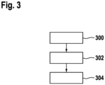
- FIG. 3 An exemplary method for generating a decision tree, in particular for assigning cost parameters and benefit parameters, is shown in a flow diagram.
- a decision tree based on expert knowledge is created for error information or symptom information.
- the decision tree can include a large number of diagnostic process steps, which can be sorted arbitrarily or according to the expert's assessment.
- a second step 302 historical field data is provided by the server 12.
- the field data used was determined from a large number of electric bicycles and provided to the server 12 via external devices.
- the data is provided to the server 12 by means of the diagnostic devices.
- the historical field data includes, in particular, information about which diagnostic method steps and the order of the diagnostic method steps were used to determine errors based on error information and symptom information.
- the field data can be collected using traditional methods such as statistics about the errors and the causes.
- the source of the field data can be, for example, log data, statistics from stored Errors and warnings, personal feedback from observations or ratings and information from service reports.
- a third step 304 the use of the fault tree is fed back using a feedback loop, so that it is continuously developed further.
- the feedback continuously adapts and optimizes the cost parameter and/or the benefit parameter of the individual diagnostic process steps.
- the feedback is designed as a binary answer, with the answer being directed to the question of whether or not the correct cause or error was determined after running through the proposed or used decision tree.
- the probability that a diagnostic process step will be offered as a sensible option at a run in the decision tree is increased if this previously helped in troubleshooting and reduced if the diagnostic process step did not contribute to the solution.
- the decision tree is adapted in such a way that the correct error is determined with minimal effort based on the error information or the symptom information.
- the effort is defined here, for example, as a weighted sum of the effort of the individual diagnostic process steps.
- the effort of a diagnostic process step is defined as the sum of its costs. This cost consists of i elements. These are examples: time, monetary costs, complexity and possibly other factors.
- a diagnostic method step m is defined as the progress toward an exact diagnosis after applying the diagnostic method step from the state before the diagnostic procedure step. This value is also standardized between [0; 1], where 0 means “no improvement” and 1 means "cause is now exactly determined”.
- Utility parameter N [0,1]
- the effort of an individual diagnostic process step is defined as the sum of the costs that are necessary to carry out this diagnostic process step.
- the costs are initially seen as the time required to carry out the diagnostic process step, but also the complexity and the need for additional tools. This corresponds to the optimal path to a correct diagnosis.
- a sequence of diagnostic process steps is proposed in which the diagnostic process steps with the lowest costs (easy and quick to carry out) provide the greatest information about the cause of the error.
- the user should be able to identify the existing error or the cause of the error as quickly and easily as possible with the highest possible accuracy.
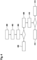
- a further exemplary method for diagnosing the electric bicycle 16 using a decision tree is shown in a flowchart.
- the diagnosis is carried out, for example, in part on the external device 100.
- the external device 100 is provided with symptom information.
- the symptom information is recorded, for example, via a user input from the driver.
- the symptom information is designed as a reduced performance of the drive unit 26 of the electric bicycle 16.
- a first diagnostic method step is started based on the symptom information.
- an optical signal characteristic is detected by the external device 100, in particular a camera (not shown) of the external device 100.
- the optical signal parameter is, for example, an image of the drive unit. The image is taken as an example by the user and under the guidance of the external device.
- the optical signal characteristic is then signal processed in a step 404.
- the signal processing includes, for example, pattern recognition, which determines whether there is visible damage to the drive unit.
- step 406 If there is visible damage, a replacement of the component is suggested in step 406.
- a further diagnostic process step is started in a step 408.
- the user is requested to ride the electric bicycle 16 with the drive unit 26 activated by means of the board computer 30 of the electric bicycle 16 or the external device 100. While driving, an acoustic signal characteristic is detected by a microphone (not shown) of the external device 100.
- step 410 further signal processing takes place, with a frequency analysis of the acoustic signal characteristic taking place.
- the frequency analysis is carried out, for example, using a machine learning system, preferably a deep learning algorithm.
- the replacement of the component or the drive unit 26 is suggested in a step 412, for example.
- the error can be determined using the frequency analysis, it is communicated to the user in a step 414 via the on-board computer 30 or the external Device 100 displayed.
- the frequency analysis can be used to determine and display a precise determination of the error, for example a defective electric motor, a worn gear or a damaged crankshaft.
Landscapes
- Engineering & Computer Science (AREA)
- Physics & Mathematics (AREA)
- General Physics & Mathematics (AREA)
- Mechanical Engineering (AREA)
- Business, Economics & Management (AREA)
- Human Resources & Organizations (AREA)
- Entrepreneurship & Innovation (AREA)
- Quality & Reliability (AREA)
- Strategic Management (AREA)
- Tourism & Hospitality (AREA)
- Operations Research (AREA)
- General Business, Economics & Management (AREA)
- Marketing (AREA)
- Theoretical Computer Science (AREA)
- Chemical & Material Sciences (AREA)
- Combustion & Propulsion (AREA)
- Economics (AREA)
- Testing And Monitoring For Control Systems (AREA)
- Management, Administration, Business Operations System, And Electronic Commerce (AREA)
Applications Claiming Priority (1)
| Application Number | Priority Date | Filing Date | Title |
|---|---|---|---|
| DE102022204945.4A DE102022204945A1 (de) | 2022-05-18 | 2022-05-18 | Verfahren zur Diagnose eines Fahrrads |
Publications (1)
| Publication Number | Publication Date |
|---|---|
| EP4280141A1 true EP4280141A1 (fr) | 2023-11-22 |
Family
ID=86185131
Family Applications (1)
| Application Number | Title | Priority Date | Filing Date |
|---|---|---|---|
| EP23169530.5A Pending EP4280141A1 (fr) | 2022-05-18 | 2023-04-24 | Procédé de diagnostic d'une bicyclette |
Country Status (4)
| Country | Link |
|---|---|
| US (1) | US12530933B2 (fr) |
| EP (1) | EP4280141A1 (fr) |
| CN (1) | CN117087801A (fr) |
| DE (1) | DE102022204945A1 (fr) |
Cited By (1)
| Publication number | Priority date | Publication date | Assignee | Title |
|---|---|---|---|---|
| WO2024235780A1 (fr) * | 2023-05-12 | 2024-11-21 | Zf Friedrichshafen Ag | Dispositif de génération d'un code d'erreur pour un pédelec |
Families Citing this family (1)
| Publication number | Priority date | Publication date | Assignee | Title |
|---|---|---|---|---|
| DE102019218724A1 (de) * | 2019-12-03 | 2021-06-10 | Robert Bosch Gmbh | Datenverwaltungsvorrichtung für ein Zweirad |
Citations (4)
| Publication number | Priority date | Publication date | Assignee | Title |
|---|---|---|---|---|
| US20160321845A1 (en) * | 2014-01-21 | 2016-11-03 | Panasonic Intellectual Property Management Co., Ltd. | Information processing system for electric two-wheeled vehicle, electric two-wheeled vehicle, electric equipment unit, and key for electric two-wheeled vehicle |
| US20200017155A1 (en) * | 2016-12-12 | 2020-01-16 | Jiangsu Hongbao Hardware Co., Ltd. | Systems and methods for determining abnormal information associated with a vehicle |
| US20200250246A1 (en) * | 2019-02-05 | 2020-08-06 | Sram, Llc | Component based automated identification of a configurable vehicle |
| DE102019218724A1 (de) * | 2019-12-03 | 2021-06-10 | Robert Bosch Gmbh | Datenverwaltungsvorrichtung für ein Zweirad |
Family Cites Families (23)
| Publication number | Priority date | Publication date | Assignee | Title |
|---|---|---|---|---|
| WO2007132576A1 (fr) * | 2006-05-15 | 2007-11-22 | Sharp Kabushiki Kaisha | Dispositif et système d'assistance au diagnostic |
| WO2010135472A2 (fr) * | 2009-05-19 | 2010-11-25 | Ev-Ip, Llc | Procédés et dispositif pour utiliser des véhicules électriques |
| US8989950B2 (en) * | 2011-02-15 | 2015-03-24 | Bosch Automotive Service Solutions Llc | Diagnostic tool with smart camera |
| JP5303615B2 (ja) | 2011-07-29 | 2013-10-02 | 株式会社シマノ | 自転車用電装システムの診断装置 |
| JP5536736B2 (ja) * | 2011-10-24 | 2014-07-02 | 本田技研工業株式会社 | 車両診断方法及び外部診断装置 |
| US20140075356A1 (en) * | 2012-09-07 | 2014-03-13 | Service Solutions U.S. Llc | Diagnostic Hub |
| US9418490B2 (en) * | 2012-09-07 | 2016-08-16 | Bosch Automotive Service Solutions Inc. | Data display with continuous buffer |
| US20140129077A1 (en) * | 2012-11-05 | 2014-05-08 | Service Solutions U.S. Llc | Scan tool with configurable shortcuts |
| US9613469B2 (en) * | 2013-03-15 | 2017-04-04 | Bosch Automotive Service Solutions Inc. | Graphical user interface with vehicle scanned function |
| US10240548B2 (en) * | 2013-07-23 | 2019-03-26 | Nxp Usa, Inc. | Control system and method of operating a control system |
| US9183681B2 (en) * | 2013-07-31 | 2015-11-10 | Bosch Automotive Service Solutions Inc. | Diagnostic tool with parts ordering system |
| DE102016200289A1 (de) | 2016-01-13 | 2017-07-13 | Robert Bosch Gmbh | Verfahren zur Diagnose eines elektrischen Energiespeichers und Diagnosevorrichtung für einen elektrischen Energiespeicher |
| US10242511B2 (en) * | 2016-12-29 | 2019-03-26 | Bosch Automotive Service Solutions Inc. | Using on-board monitoring (mode 6) misfire tests in data stream and physical addressing |
| US20180190043A1 (en) * | 2016-12-29 | 2018-07-05 | Bosch Automotive Service Solutions Inc. | Mileage Tracking Provisioning |
| US20190279438A1 (en) * | 2018-03-09 | 2019-09-12 | Progress Rail Locomotive Inc. | Systems and methods for servicing a vehicle |
| EP3584658B1 (fr) * | 2018-04-25 | 2024-06-05 | Shenzhen Launch Software Co., Ltd. | Procédé, système, dispositif et support d'informations lisible par ordinateur permettant de diagnostiquer un véhicule |
| DE102018218579A1 (de) | 2018-10-30 | 2020-04-30 | Robert Bosch Gmbh | Verfahren und Vorrichtung zur Erkennung eines Defekts einer Batterie in einem Niederspannungsbordnetz eines Elektrofahrzeugs |
| IT202100020564A1 (it) * | 2021-07-30 | 2023-01-30 | Campagnolo Srl | Sistema e metodo di diagnosi di un impianto frenante idraulico di bicicletta del tipo a disco |
| US11455841B1 (en) * | 2021-08-26 | 2022-09-27 | Innova Electronics Corporation | System and method for selective vehicle data retrieval |
| CN114013554B (zh) * | 2021-10-28 | 2023-06-23 | 南京懂玫驱动技术有限公司 | 驱动组件管理系统、故障检测方法及电助力自行车 |
| DE102021213020A1 (de) * | 2021-11-19 | 2023-05-25 | Robert Bosch Gesellschaft mit beschränkter Haftung | Verfahren zur Wartung eines Elektrofahrrads |
| US12216464B2 (en) * | 2022-05-17 | 2025-02-04 | Honeywell International Inc. | Augmented reality system for diagnosing system operation |
| US20240420520A1 (en) * | 2023-06-19 | 2024-12-19 | Robert Bosch Gmbh | Systems and Methods for Volumetric Efficiency Diagnostic of an Engine |
-
2022
- 2022-05-18 DE DE102022204945.4A patent/DE102022204945A1/de active Pending
-
2023
- 2023-04-24 EP EP23169530.5A patent/EP4280141A1/fr active Pending
- 2023-05-17 US US18/318,956 patent/US12530933B2/en active Active
- 2023-05-18 CN CN202310565116.9A patent/CN117087801A/zh active Pending
Patent Citations (4)
| Publication number | Priority date | Publication date | Assignee | Title |
|---|---|---|---|---|
| US20160321845A1 (en) * | 2014-01-21 | 2016-11-03 | Panasonic Intellectual Property Management Co., Ltd. | Information processing system for electric two-wheeled vehicle, electric two-wheeled vehicle, electric equipment unit, and key for electric two-wheeled vehicle |
| US20200017155A1 (en) * | 2016-12-12 | 2020-01-16 | Jiangsu Hongbao Hardware Co., Ltd. | Systems and methods for determining abnormal information associated with a vehicle |
| US20200250246A1 (en) * | 2019-02-05 | 2020-08-06 | Sram, Llc | Component based automated identification of a configurable vehicle |
| DE102019218724A1 (de) * | 2019-12-03 | 2021-06-10 | Robert Bosch Gmbh | Datenverwaltungsvorrichtung für ein Zweirad |
Cited By (1)
| Publication number | Priority date | Publication date | Assignee | Title |
|---|---|---|---|---|
| WO2024235780A1 (fr) * | 2023-05-12 | 2024-11-21 | Zf Friedrichshafen Ag | Dispositif de génération d'un code d'erreur pour un pédelec |
Also Published As
| Publication number | Publication date |
|---|---|
| US12530933B2 (en) | 2026-01-20 |
| US20230410571A1 (en) | 2023-12-21 |
| DE102022204945A1 (de) | 2023-11-23 |
| CN117087801A (zh) | 2023-11-21 |
Similar Documents
| Publication | Publication Date | Title |
|---|---|---|
| DE112017006567B4 (de) | System und verfahren zum bereitstellen einer fahrerausbildung für einen menschlichen insassen eines autonomen fahrzeugs | |
| EP4280141A1 (fr) | Procédé de diagnostic d'une bicyclette | |
| DE102022203816A1 (de) | Verfahren zur Ermittlung eines Fahrerzustands eines motorunterstützten Fahrzeugs; Verfahren zum Trainieren eines maschinellen Lernsystems; motorunterstütztes Fahrzeug | |
| DE102018100191A1 (de) | Systeme und Verfahren zur Erkennung von unerwarteten Ereignissen bei Elektrofahrrädern | |
| DE202017006582U1 (de) | Fahrradsteuereinrichtung | |
| DE112019001487T5 (de) | Zustandsbestimmungsvorrichtung, Zustandsbestimmungsprogramm und computerlesbares nichtvergänglich greifbares Speichermedium | |
| DE112021005122T5 (de) | System zum Erfassen des Zustands eines Fahrzeugkörpers, Eleltrofahrrad, Verfahren zum Erfassen des Zustands eines Fahrzeugskörpers und Programm | |
| DE102019118275A1 (de) | Erzeugungsvorrichtung, Komponentensteuervorrichtung, Erzeugungsverfahren, Komponentensteuerverfahren, Computerprogramm und Lernmodell | |
| EP3094548B1 (fr) | Procédé et dispositif pour faire fonctionner un vélo à assistance électrique | |
| DE102022204948A1 (de) | Verfahren zur Diagnose eines Fahrrads | |
| EP4505764A1 (fr) | Procédé pour adapter un dispositif de commande pour un vélo électrique | |
| DE102020206102A1 (de) | Kurbelwinkel-schätzvorrichtung eines menschlich angetriebenen fahrzeugs und steuerungsvorrichtung eines menschlich angetriebenen fahrzeugs | |
| DE102011106900A1 (de) | Verfahren zur Erkennung einer Handbetätigung einer Lenkvorrichtung und Kraftfahrzeug mit einer Vorrichtung zur Durchführung des Verfahrens | |
| WO2025008260A1 (fr) | Procédé pour déterminer au moins un algorithme de fonctionnement de bicyclette spécifique au conducteur et/ou spécifique à la bicyclette | |
| DE102021130164A1 (de) | Bereitstellen von auf ein Fahrziel bezogenen Parkplatzdaten beim Führen eines Kraftfahrzeugs | |
| DE102020207825A1 (de) | Verfahren zur Geschwindigkeitsüberwachung bei einem Zweirad | |
| DE102023105062A1 (de) | Verfahren oder system zum verwenden menschlicher fahreigenschaften in einem autonomen oder teilautonomen fahrverfahren oder -system | |
| DE102022131438A1 (de) | Informationsverarbeitungsvorrichtung für ein muskelkraftbetriebenes fahrzeug, informationsverarbeitungsverfahren für ein muskelkraftbetriebenes fahrzeug, informationsverarbeitungssystem für ein muskelkraftbetriebenes fahrzeug und computerprogramm | |
| DE112022004488T5 (de) | Straßenoberflächenzustandsdetektionssystem und Straßenoberflächenzustandsdetektionsverfahren | |
| DE102022203124A1 (de) | Computer-implementiertes System und Verfahren zum Überwachen der Funktionsfähigkeit einer automatisierten Fahrfunktion | |
| WO2023094099A1 (fr) | Procédé d'identification du conducteur d'un véhicule | |
| DE102021128784A1 (de) | Steuervorrichtung für ein mit muskelkraft angetriebenes fahrzeug | |
| DE102024206216A1 (de) | Verfahren zur Überprüfung eines Fahrradalgorithmus | |
| DE102025122227A1 (de) | Unterstützungsvorrichtung für ein muskelkraftbetriebenes fahrzeug, übertragungsvorrichtung für ein muskelkraftbetriebenes fahrzeug und steuersystem für ein muskelkraftbetriebenes fahrzeug | |
| DE102025130584A1 (de) | System zur Berechnung elektrischer Effizienz von elektrischem Fahrzeug, System zur Berechnung verfügbarer Fahrstrecke, Programm und Verfahren |
Legal Events
| Date | Code | Title | Description |
|---|---|---|---|
| PUAI | Public reference made under article 153(3) epc to a published international application that has entered the european phase |
Free format text: ORIGINAL CODE: 0009012 |
|
| STAA | Information on the status of an ep patent application or granted ep patent |
Free format text: STATUS: THE APPLICATION HAS BEEN PUBLISHED |
|
| AK | Designated contracting states |
Kind code of ref document: A1 Designated state(s): AL AT BE BG CH CY CZ DE DK EE ES FI FR GB GR HR HU IE IS IT LI LT LU LV MC ME MK MT NL NO PL PT RO RS SE SI SK SM TR |
|
| STAA | Information on the status of an ep patent application or granted ep patent |
Free format text: STATUS: REQUEST FOR EXAMINATION WAS MADE |
|
| 17P | Request for examination filed |
Effective date: 20240522 |
|
| RBV | Designated contracting states (corrected) |
Designated state(s): AL AT BE BG CH CY CZ DE DK EE ES FI FR GB GR HR HU IE IS IT LI LT LU LV MC ME MK MT NL NO PL PT RO RS SE SI SK SM TR |