EP4280177B1 - Systèmes et procédés d'application de marquages - Google Patents
Systèmes et procédés d'application de marquages Download PDFInfo
- Publication number
- EP4280177B1 EP4280177B1 EP23201210.4A EP23201210A EP4280177B1 EP 4280177 B1 EP4280177 B1 EP 4280177B1 EP 23201210 A EP23201210 A EP 23201210A EP 4280177 B1 EP4280177 B1 EP 4280177B1
- Authority
- EP
- European Patent Office
- Prior art keywords
- marking
- data
- target location
- vehicle
- application tool
- Prior art date
- Legal status (The legal status is an assumption and is not a legal conclusion. Google has not performed a legal analysis and makes no representation as to the accuracy of the status listed.)
- Active
Links
Images


Classifications
-
- G—PHYSICS
- G05—CONTROLLING; REGULATING
- G05D—SYSTEMS FOR CONTROLLING OR REGULATING NON-ELECTRIC VARIABLES
- G05D1/00—Control of position, course, altitude or attitude of land, water, air or space vehicles, e.g. using automatic pilots
- G05D1/02—Control of position or course in two dimensions
- G05D1/021—Control of position or course in two dimensions specially adapted to land vehicles
- G05D1/0231—Control of position or course in two dimensions specially adapted to land vehicles using optical position detecting means
- G05D1/0246—Control of position or course in two dimensions specially adapted to land vehicles using optical position detecting means using a video camera in combination with image processing means
-
- E—FIXED CONSTRUCTIONS
- E01—CONSTRUCTION OF ROADS, RAILWAYS, OR BRIDGES
- E01C—CONSTRUCTION OF, OR SURFACES FOR, ROADS, SPORTS GROUNDS, OR THE LIKE; MACHINES OR AUXILIARY TOOLS FOR CONSTRUCTION OR REPAIR
- E01C23/00—Auxiliary devices or arrangements for constructing, repairing, reconditioning, or taking-up road or like surfaces
- E01C23/16—Devices for marking-out, applying, or forming traffic or like markings on finished paving; Protecting fresh markings
-
- E—FIXED CONSTRUCTIONS
- E01—CONSTRUCTION OF ROADS, RAILWAYS, OR BRIDGES
- E01F—ADDITIONAL WORK, SUCH AS EQUIPPING ROADS OR THE CONSTRUCTION OF PLATFORMS, HELICOPTER LANDING STAGES, SIGNS, SNOW FENCES, OR THE LIKE
- E01F9/00—Arrangement of road signs or traffic signals; Arrangements for enforcing caution
- E01F9/50—Road surface markings; Kerbs or road edgings, specially adapted for alerting road users
- E01F9/576—Traffic lines
-
- G—PHYSICS
- G06—COMPUTING OR CALCULATING; COUNTING
- G06V—IMAGE OR VIDEO RECOGNITION OR UNDERSTANDING
- G06V20/00—Scenes; Scene-specific elements
- G06V20/50—Context or environment of the image
- G06V20/56—Context or environment of the image exterior to a vehicle by using sensors mounted on the vehicle
- G06V20/58—Recognition of moving objects or obstacles, e.g. vehicles or pedestrians; Recognition of traffic objects, e.g. traffic signs, traffic lights or roads
- G06V20/582—Recognition of moving objects or obstacles, e.g. vehicles or pedestrians; Recognition of traffic objects, e.g. traffic signs, traffic lights or roads of traffic signs
-
- G—PHYSICS
- G06—COMPUTING OR CALCULATING; COUNTING
- G06V—IMAGE OR VIDEO RECOGNITION OR UNDERSTANDING
- G06V20/00—Scenes; Scene-specific elements
- G06V20/50—Context or environment of the image
- G06V20/56—Context or environment of the image exterior to a vehicle by using sensors mounted on the vehicle
- G06V20/588—Recognition of the road, e.g. of lane markings; Recognition of the vehicle driving pattern in relation to the road
-
- G—PHYSICS
- G05—CONTROLLING; REGULATING
- G05D—SYSTEMS FOR CONTROLLING OR REGULATING NON-ELECTRIC VARIABLES
- G05D1/00—Control of position, course, altitude or attitude of land, water, air or space vehicles, e.g. using automatic pilots
- G05D1/02—Control of position or course in two dimensions
- G05D1/021—Control of position or course in two dimensions specially adapted to land vehicles
- G05D1/0276—Control of position or course in two dimensions specially adapted to land vehicles using signals provided by a source external to the vehicle
- G05D1/0278—Control of position or course in two dimensions specially adapted to land vehicles using signals provided by a source external to the vehicle using satellite positioning signals, e.g. GPS
Definitions
- This disclosure relates generally to systems and methods to apply markings to a surface.
- machines may be used to apply corresponding road markings.
- road markings are often applied by hand using stencils. The associated costs with applying such markings are largely dependent upon the personnel required to apply painting as well as to direct traffic near the location where the markings are being applied. Additionally, because stencils are hand painted, workers may be exposing themselves to potential injury from collisions with vehicles or work vans.
- a method in one example, includes storing marking data to specify at least one selected marking to apply at a target location along a vehicle path of travel, the marking data including a machine-readable description and a marking reference coordinate frame for the selected marking.
- the method also includes generating task plan data to apply the selected marking based on the marking data and at least one parameter of an application tool.
- the method also includes determining a location and orientation of the application tool with respect to the vehicle path of travel based on location data representing a current location of a vehicle carrying the application tool.
- the method also includes computing a joint-space trajectory to enable the application tool to apply the selected marking at the target location based on the task plan data and the determined location of the application tool.
- the method also includes computing a transformation to correlate the fiducial coordinate frame for each of the sensed fiducials along the application path of travel to a spatial coordinate frame for respective fiducials sensed along a previous survey path of travel.
- the application path of travel is to approximate the survey path of travel.
- the method also includes determining a pose of the application tool along the application path of travel based on the transformation and the geospatial coordinate data.
- a system may apply markings to a surface.
- the system includes a global positioning system device to provide geospatial coordinate data representing a current pose of a vehicle carrying an application tool along an application path of travel.
- At least one other sensor is provided to sense fiducials along the application path of travel.
- One or more non-transitory machine-readable media store instructions and marking data.
- the marking data describes at least one selected marking that the application tool is to apply at a target location, including a marking reference frame for the selected marking.
- a processor is provided to execute the instructions to at least: determine a spatial coordinate frame for the fiducials sensed by the at least one other sensor along the application path of travel.
- the marking may include adding a graphical object (e.g., one or more symbols, words, lines or a combination thereof), removing or changing the surface (e.g., cleaning, sealing or coating, cutting and/or milling) and the like.
- a user can utilize a planning system, operating on a computing device, which includes a graphical user interface (GUI) to select one or more markings and assign the selected marking to a target location.
- GUI graphical user interface
- This can be done in an office or the on-site by a traffic engineer, highway engineer, city planner or the like using simple drag and drop operations afforded by the GUI (e.g., a CAD-style interface).
- a corresponding task plan can be generated to define a process for applying the selected marking using a given application tool, though independent of a target location.
- the task plan is generated based on the marking data (independent of the target location) and one or more parameters of the application tool (e.g., paint head configuration, distance to target and spray nozzle) to apply the selected marking at a zero reference frame.
- the vehicle carrying the application tool can then be advanced along an application path of travel (e.g., corresponding to the same path as the survey path of travel). Once the vehicle arrives at or near the target location, such that the application tool is able to reach the target location, the vehicle can be stopped or slowed down.
- guidance may be provided to the operator to stop the vehicle based on global positioning system (GPS) data and/or other sensor data.
- GPS global positioning system
- a computing device is programmed to determine a current pose of the application tool based on location data that is derived from one or more sensors mounted at fixed known locations with respect to the vehicle, as disclosed herein.
- the operator can trigger the application of the selected marking (e.g., in response to a user input).
- a corresponding joint space trajectory can be computed to apply the marking at the target location (e.g., the original or modified target location).
- the vehicle may be stationary or moving during application of the marking at the target location.
- the marking may be a new marking applied to a clean (e.g., unmarked) surface or be applied to overpaint an existing marking.
- uncertainty associated with one or more sensors may be updated in real time and used to weight the sensor values utilized by the sensor fusion accordingly.
- the sensor fusion may, based on determining that one or more sensors have a high degree of confidence, select such one or more high-confidence sensors to localize the pose of the vehicle while disregarding the data from the other sensors having higher uncertainty (lower confidence).
- data from a single high-confidence sensor may be used in some circumstances; whereas, in other examples, data from multiple sensors may be used.
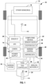
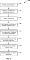
- FIG. 1 depicts an example of a system 10 to apply markings to one or more target locations.
- the system 10 is demonstrated in FIG. 1 as being integrated into a vehicle 12.
- the vehicle 12 can be a truck or other vehicle that can traverse the roadway or other surface along which one or more target locations can be identified for applying respective markings.
- the vehicle 12 may be an autonomous vehicle and/or manually driven vehicle.
- the system 10 is configured to perform precision localization of the vehicle 12 such as to ascertain the position and orientation (i.e., pose) of a vehicle reference coordinate system to within a predetermined accuracy (e.g., less than one inch, such as to within 1cm or less).
- the system 10 can include a GPS device (e.g., a GPS receiver) 14 to provide geospatial coordinates for a reference frame of the vehicle.
- a GPS device e.g., a GPS receiver
- the GPS device 14 may provide centimeter precision for the vehicle 12 provided that the sensing antenna remains unobstructed by trees, bridges or other objects (e.g., tall buildings) that can interfere with the GPS accuracy.
- the system 10 includes one or more other sensors 16 that may be utilized to sense fiducials along the vehicle's path of travel to enable precision localization.
- fiducials can be any fixed object along the vehicle's path of travel that can be sensed by the sensors 16.
- fiducials may include existing road markings, trees, telephone poles, fire hydrants, mail boxes, signs, curbs, manhole covers, water-main accesses, gas-line markings, buried cable markings, curbs, grates, speed bumps or the like.
- Different types of sensors may be utilized to detect different types of fiducials that may be distributed along the path of travel or fiducials associated with the vehicle that vary as a function of vehicle motion.
- sensors 16 include LIDAR, radar, ground penetrating radar, sonar, ultrasonic sensors, wheel encoders, accelerometers, odometry sensors, wheel angle sensors, color camera as well as other sensing modalities that can detect such features that may be detectable along the path of travel.
- a camera 18 e.g., one or more digital color cameras. The camera 18 thus operates to acquire images (e.g., digital color images at a corresponding frame rate) along the path of travel of the vehicle 12.
- the camera 18 includes a ground-facing camera adjacent an application tool 24 and configured with a field of view that includes a zone of reachability for the application tool.
- the system 12 can include a sensor interface 20 that can perform initial sensor processing (e.g., filtering, analog-to-digital conversion, and the like) to provide an aggregate sensor data to a computing device 22.
- the sensor interface may be integrated into the computing device 22.
- the computing device 22 is configured to process the sensor data, including from the GPS 14, camera 18 as well as other sensors 16.
- the computing device is also configured to provide instructions to control the application tool 24.
- a tool controller 26 can be connected with the computing device 22 via a connection (e.g., physical or wireless connection) and the computing device can provide commands (e.g., in the form of a joint-space trajectory) to the controller 26 that are utilized to apply each selected marking at respective target locations.
- the application tool 24 is implemented as a robot.
- the robot 24 is an industrial robot, such as a painting robot, that is commercially available from Yaskawa America, Inc. of Miamisburg, Ohio. Additionally or alternatively, other types of application tools may be used in other examples, such as may vary depending on the type of markings to be applied. While the example system 10 in FIG. 1 is demonstrated as including a single application tool 24, in other examples, more than one application tool (e.g., a plurality of robots) may be implemented on the vehicle 12 for performing different marking functions, including performing multiple marking functions concurrently.
- the computing device 22 can be implemented as a portable device that can be carried on a vehicle 12.
- the computing device 12, for example can include one or more non transitory machine-readable media to store executable instructions and related data.
- the computing device 22 can also include one or more processors for executing the instructions and computing information to enable command instructions to be provided to the controller 26.
- the example application tool 24 includes a tool reference frame 28 such as providing two-dimensional coordinate system having an origin at a fixed location with respect to the tool 24.
- the origin and coordinate system 28 also has a predefined location and orientation with respect to a vehicle reference frame 30.
- Each of the sensors 14, 16 and 18 can be calibrated to provide sensor information with respect to the vehicle reference frame 30.
- the computing device 22 can compute corresponding transformations for each sensor such that the sensor information is spatially registered with respect to the vehicle reference frame 30.
- the system 10 also includes a marking system 32 that can supply materials or other features to the application tool 24 for applying the marking at the target location.
- the marking system 32 can include one or more volumes of paint or other coating materials that can be fluidly connected with the application tool 24, such that upon activation of the tool, a controlled amount of marking material is applied to the target location.
- the marking system 32 may include sensors (e.g., a sonar or ultrasonic sensor) and signal processing to determine and control a distance between an applicator of the tool and the surface (e.g., road). The marking system 32 thus may provide sensor signal or other information utilized by the controller 26 to maintain a desired distance during application of each selected marking.
- the computing device 22 is programmed to execute instructions for performing various functions associated with determining location and programming the tool 24.
- the computing device includes marking data 34 that can be pre-computed for each selected marking that is to be applied.
- the marking data 34 specifies a type of marking that has been selected, size (or scaling of the selected marking) as well as spatial coordinates of a marking reference frame for the target location to which the selected marking is to be applied.
- Other data associated with application of the marking can also be stored as part of marking data 34.
- Such other marking data 34 can include, for example task plan data, describing a process for the application tool to create the selected marking as a function of the marking reference frame and one or more tool parameters implemented by the tool 24 and associated controller 26 to apply the marking.
- the target location can correspond to spatial coordinates of a marking reference frame that has been determined based on location data derived from sensor data (e.g., from the GPS 14, camera 18 and/or other sensors 16).
- the sensor data corresponds to fused sensor data generated by a sensor fusion function 36.
- the sensor fusion function 36 is programmed (e.g., machine-readable instructions) to receive sensor data from the GPS sensor 14 and from one or more other sensors 16 and/or 18 as the vehicle 12 is along the path of travel.
- the path of travel may refer to a survey path of travel which corresponds to the path of travel and trajectory of the vehicle 12 as it maps out the locations to which one or more markings will be applied.
- the path of travel may also correspond to an application path of travel which is the pose of the vehicle 12 as it moves along the path for applying the marking at each respective target location defined by the marking data 34.
- the sensor fusion function 36 thus is programmed to fuse the sensor data from sensors 16 and/or 18 with the geospatial data from the GPS to provide corresponding fused location data representing a precise (e.g., within about 1cm) current location of the vehicle 12.
- the fusion function 36 is programmed to further determine an uncertainty associated with a measure of location accuracy for each of the geospatial data (e.g., from GPS sensor 14) as well as each other sensor data (e.g., from sensors 16 and/or 18).
- a weight value can be assigned to each of the geospatial data and sensor data that are acquired to provide weighted data.
- the weighting may be implemented by an extended Kalman filter that implements weighting to the sensors 14, 16 and 18 that is inversely proportional to the sensing modality measurement uncertainty that is determined for each respective sensor.
- the weighting further may vary over time as the uncertainty may vary during the sensing process. For example, the measurement uncertainty (e.g., error) of the GPS sensor 14 may increase if the GPS sensing is obstructed such as by buildings, trees, bridges, and the like.
- the sensor fusion function 36 further may aggregate each of the weighted sensor data that is acquired to provide the corresponding fused location data. In this way, the position and orientation of the vehicle 12 and, in turn, the application tool 24 can be determined as a function of the fused sensor data.
- a location calculator function 38 can be programmed to implement respective transformations to transform corresponding sensor data from each of the sensors 14, 16 and 18 into a common coordinate reference frame to facilitate precision localization.
- the computing device 22 is programmed with a transformation for each sensor 14, 16 and 18 that is calibrated with respect to the vehicle reference frame 30.
- the transformation thus can be utilized to compute a spatial transformation for fiducials detected by each of the sensors 16 and 18 into the reference frame 30 of the vehicle 12 and the location calculator can utilize the transformed spatial coordinates from such sensors to compute an indication of vehicle pose and/or vehicle motion.
- the location calculator 38 can provide a precision estimate of vehicle pose.
- the sensor fusion function 36 can utilize the transformed sensor data for providing the fused sensor data, which may be utilized by the location calculator.
- the precision localization of the vehicle reference frame 30 can be further translated to the reference frame 28 of the application tool (based on the known spatial geometry between reference frames 28 and 30) over the vehicle path of travel.
- the computing device 22 also includes a marking control function 40.
- the marking control function 40 can include a joint-space trajectory calculator (see, e.g., FIG. 8 ) programmed to compute a joint-space trajectory to enable application tool 24 to apply each selected marking at the target location.
- the marking control function 40 computes the joint-space trajectory based on the marking data 34 (e.g., the task plan that has been determined for the selective marking) and the determined pose of the application tool 24 (e.g., the current pose of tool reference coordinate frame 28).
- the task plan may include multiple sub-process plans associated with the application of a given marking that may involve more than one application tool.
- one sub-process plan may be to apply thermoplastic marking materials and another may be to apply heat in order to achieve suitable thermoset bonding to the underlying surface.
- one sub-process plan may apply heat to the surface to be coated, and a next sub-process plan to apply a marking material such as paint to the heated surface.
- the computed joint-space trajectory thus may likewise include multiple joint-space trajectories for operating at the target location according to the multiple sub-process plans associated with the application of each respective marking.
- the marking control function 40 provides the computed joint-space trajectory to the tool controller 26, which controls one or more actuators of the tool 24 to apply the marking at the target location.
- the marking control 40 can also control changes to the marking data 34 and/or respond to user input instructions entered by an operator to control operation of the tool 24.
- a marking zone can be determined for the application tool 24 and utilized (e.g., by the marking control 40) to control the tool 24.
- the marking zone defines a spatial region (or volume) of reachability for the application tool 24.
- the tool 24 has sufficient reachability to apply at least a substantial portion of the selected marking at the target location.
- the substantial portion of the selected marking can be determined based on the overall size of the marking relative to the known reachability of the application tool. For example, if a given marking is larger than the zone of reachability for the application tool, the given marking may be divided into multiple marking portions.
- the vehicle can be moved to a first marking zone to apply one portion and after that has been completed the vehicle may be moved to a second location to apply the next marking portion, and so forth until the entire marking has been applied.
- the marking control 40 can be programmed to determine whether the vehicle location and orientation is within the marking zone.
- the marking control 40 may further generate guidance to inform a user whether or not the vehicle is in the marking zone.
- the guidance may be in the form of an audible and/or visual alert.
- the computing device 22 can generate a graphical representation of the selected marking that is superimposed onto a current camera image that has been acquired (e.g., by a ground facing camera 18) to include the target location.
- the superimposed image may be visualized on a display within the vehicle passenger compartment.
- the display is provided a visualization of the target marking that has been scaled and graphically rendered at the target location (based on localization data determined by the location calculator 38). This affords the user an opportunity to decide whether or not to actually apply the marking with the current orientation at such target location or if the target location and/or orientation should be adjusted.
- an adjustment to the target location may include translation and/or rotation of the selected marking with respect to the target location in response to a user input, which provides a modified target location. If the target location and/or orientation are modified, the marking control 40 may compute or recompute the joint space trajectory for the selected marking according to the modified target location. If the target location is not adjusted in response to a user input, the user can instruct the computing device 20 to proceed with applying the selected marking at the original target location. In response to such user input, the marking control 40 can compute the joint-space trajectory (if not already computed) based on the task plan and the current determined pose of the application tool reference frame 28.
- the controller 26 thus employs the joint-space trajectory that has been computed to apply the selected marking at the target location (e.g., the original or modified target location). This process will be repeated for any number of selected markings along the vehicle path of travel based on the marking data 34.
- the vehicle may be controlled (e.g., automatically and/or manually by the user) to move along the path of travel.
- the location data will update according to a sample rate that sensor data is acquired (e.g., by sensors 14, 16 and/or 18) along the path of travel.
- the updated location data can be applied to recompute the joint-space trajectory provided that the target location is within the zone of reachability for the application tool 24.
- marking control 40 intermittently recomputes a joint-space trajectory at each of the spaced apart locations along the path of travel, which can be provided to the controller 26 to control the application tool 24 to apply the marking as the vehicle moves along the path of travel. Additionally, corresponding guidance may be provided continually as the vehicle moves along the path of travel to inform the user whether or not the application tool remains within a zone of reachability for applying the selected marking. In some situations, the vehicle 12 may advance along the path of travel and stop for application of the selected marking (or a portion thereof). In other examples, the vehicle may continue to move along the path of travel (at a fixed or variable speed) during application of the selected marking.
- sensors 16 and/or 18 can be configured to sense fiducials as the vehicle moves along a survey path of travel. Fiducials may be automatically or manually selected based on survey data acquired during a previous mapping run with the vehicle. For instance, the mapping run may involve driving the vehicle 12 along the survey path of travel, which is the same path to which the markings are to be applied. As the vehicle moves along such path of travel, the camera 18 and other sensors 16 can detect fiducials along the survey path of travel. Fiducials can be identified along the survey path of travel automatically or in response to user input selecting fiducials in a GUI during or after the mapping run has been completed.
- the location calculator 38 can analyze each fiducial in a set of identified fiducials to determine a location information describing a fiducial coordinate frame for each fiducial, such as may be localized with respect to the vehicle reference frame 30.
- fiducials may be sensed by sensors 16 and/or 18 as the vehicle 12 moves along the application path of travel.
- fiducials may be recognized near expected fiducial locations specified in the survey data.
- Location calculator 38 determines a corresponding spatial coordinate frame for each fiducial that is identified along the path of travel.
- the location calculator can compute a corresponding transformation to correlate the spatial coordinate frame for each of the sensed fiducials along the application path of travel with respect to the spatial coordinate frame of the same fiducials previously identified along the survey path of travel.
- Such transformation thus can be utilized to ensure that the location data representing the pose of the vehicle reference frame 30 and tool reference frame 28 is determined to a sufficiently high degree of accuracy as it is based on combination of absolute geospatial data (from GPS 14) and relative localization (from camera 16 and other sensors 16).
- the system 10 includes a power supply 42 configured to supply electrical power to the various components of the system.
- the power supply can include a generator or other source of electrical power (e.g., an inverter, on-board vehicle power supply or the like).
- the system may also include a wireless network interface 44 to enable communication with a remote device or server (e.g., for monitoring or reporting data acquired during mapping or application phases).
- the wireless network interface 44 can be implemented to communicate digital data via a wireless communications link, such as a Wi-Fi and/or cellular data link.
- FIG. 2 depicts an example of a system to generate a survey data 102 that represents a path of travel that has been mapped out as a prospective recipient of one or more markings that are being applied.
- the system 100 utilizes data from one or more sensors that can be mounted in a fixed position with respect to a vehicle (e.g., sensors 14, 16 and 18 of FIG. 1 ) to provide corresponding sensor data 104.
- the data 104 has been acquired and stored in memory (e.g., one or more non-transitory machine-readable media).
- the data can be transferred from local storage on the vehicle to another computing device (e.g., via wireless network interface 44 or another mechanism, such as a removable storage medium).
- the same computing device e.g., device 22 - a laptop or other portable computer
- the sensor data includes GPS data 106, LIDAR data 108, camera data (e.g., image data) 110, odometry data 112, speed data 114, sonar data 116, and steering angle data 118.
- the sensor data 104 can use various combinations of the data shown in FIG. 2 to provide sufficiently precise location related information to generate the survey data 102.
- the data 104 further may be pre-processed and/or otherwise associated with other data, such as synchronized according to a time stamp.
- the data 104 can represent various attributes of a vehicle and/or surrounding environment along the path of travel.
- the system 100 includes a vehicle location calculator 120 that is programmed to produce location data based on analysis of the sensor data 104.
- the location data can represent the pose of the vehicle along one or more paths of travel.
- the location calculator 120 thus can produce the location and sensor data 122 corresponding to the pose of a vehicle reference frame (e.g., reference frame 30 of FIG. 1 ).
- Some or all of the sensor data 104 may also be included with the location and sensor data 122. As described herein, such sensor data can be transformed into the coordinate frame of the vehicle to facilitate sensor fusion 124 and localization 130 in a common reference frame.
- location calculator 120 includes a sensor fusion function 124.
- Sensor fusion function 124 is programmed to determine an indication of accuracy of each of the sensor data, which accuracy may vary over time. For example, in some situations GPS data 106 may provide precision approaching about one centimeter provided the sensor has a clear unobstructed view of the sky containing the GPS satellites. However, in certain situations, such as in tree covered areas and in highly dense urban areas with tall buildings, bridges and/or other structures, the precision of the GPS data 106 may become less precise.
- Sensor fusion function 124 thus utilizes sensor weighting function 126 to selectively weight sensor data according to the determined uncertainty associated with each unit of sensor data 104 to facilitate accurate localization of the vehicle.
- sensor weighting function 126 may be implemented as a Kalman filter configured to determine uncertainty and apply weighting coefficients to control the impact provided sample of the data 106 - 118, respectively.
- the sensor fusion 124 can increase the relative influence of sampled sensor data that is determined to have a greater amount of certainty on the location calculation by calculator 120 for each sample time instance, while reducing the influence of more uncertain data.
- sensor fusion 124 implements sensor weighting function 126 so that GPS data 106 is utilized when precision is determined to be sufficiently high, but utilizes one or more other sensor data 108-118 (e.g., precision odometry data 112, LIDAR data 108, camera data 110 and/or other sensors, such as inertial sensors data, gyroscope data and ground penetrating radar data), which are determined to be sufficiently high accuracy, to compute changes in vehicle pose (e.g., motion) with respect to the high precision GPS updates when available along the path of travel.
- sensor data 108-118 e.g., precision odometry data 112, LIDAR data 108, camera data 110 and/or other sensors, such as inertial sensors data, gyroscope data and ground penetrating radar data
- the sensor fusion function 124 evaluates the weighting values (representing uncertainty of sensor measurements), to identify a set of sensors having a low degree of uncertainty (e.g., below an uncertainty threshold individually or collectively.
- sensor fusion can determine sensors having a high degree of confidence (e.g., above a defined confidence threshold).
- the sensor fusion function 124 thus can select such one or more high-confidence sensors to use for localizing the pose of the vehicle and/or application tool, while discarding data from the other sensors determined to have greater degree of uncertainty (lower confidence). Consequently, in some examples, sensor fusion function 124 can generate fused location data from a single high-confidence sensor and, in other examples, data from multiple sensors may be used. The number of sensors used over the path of travel thus may vary according to changes in the uncertainty associated with each of the sensors.
- Sensor fusion function 124 can also include a transformation calculator 128.
- the transformation calculator 128 is configured to translate sensor data from a sensor reference frame into vehicle reference frame along the path of travel. That is the reference frame of each sensor is known a prior with respect to the vehicle reference frame. Accordingly, the transformation calculator is programmed with transformations to reconcile the relative measurements provided in each sensor data 108-118 with corresponding absolute coordinates associated with the vehicle reference frame, which may be derived from the GPS data 106 and/or from the results of previous calculations.
- LIDAR data 108 includes range and azimuth data (polar coordinates). Since the reference frame of the LIDAR sensor is known relative to a reference frame of the vehicle, the transformation calculator 128 is programmed to apply a coordinate transformation to convert the polar LIDAR data 108 to corresponding Cartesian coordinate data.
- the LIDAR data can be analyzed (manually and/or automatically) to identify fiducials along the path of travel, which may be identified as a step change from large radii (no objects returning a signal within range of the LIDAR) to distinctly smaller radii (e.g., a telephone pole reflecting a LIDAR ping).
- T_feature/world and T_feature/sensor allow computation of T_sensor/world, which can represent a high-precision lattitude and longitude of the LIDAR sensor.
- the transformation calculator can compute T_vehicle/world, which corresponds to the absolute (geospatial) coordinates of the vehicle reference frame.
- the above example for the LIDAR data 108 can be extended and modified to provide corresponding transformations for the other sensor data 110-118.
- the camera data 110 can acquire images of the road, verge areas adjacent to the road, as well fiducials within the field of view.
- the transformation calculator 128 is programmed to correlate a reference coordinate frame of the camera to the vehicle's reference frame. Through this transform, fiducials in camera coordinates can be converted to fiducials in the vehicle coordinate frame.
- the transformation calculator performs three different computations for T_vehicle/world: one from GPS+odometry, one from LIDAR and one from vision. Different numbers and types of computations would be used for different combinations of sensors.
- respective sensor weighting 126 is applied to each transformed sensor data to provide the fused location data.
- the sensor fusion function 126 thus can combine the transformed sensor data algebraically based on weightings that are proportional to credibility.
- a location vector, L includes estimates from GPS/odometry (L_gps), from LIDAR (L_lidar), and from camera (L_image).
- Vehicle location calculator 120 also includes a precision localization function 130 that is programmed to determine vehicle location data representing the pose of a reference coordinate frame of the vehicle based upon the sensor fusion 124.
- Location data 122 thus provides an indication of the vehicle pose along the path of travel of the vehicle during the mapping phase.
- Corresponding sensor data can also be stored in conjunction with the location data along the path of travel to facilitate generation of the survey data 102.
- sensor data can include raw sensor data or processed sensor data that is been transformed (by transformation calculator 128) into the reference frame of the vehicle along the path of travel, as described above.
- the survey data generator 132 Based on the selected fiducials (by fiducial selector 134) and the map data 136, the survey data generator 132 provides corresponding survey data 102.
- the survey data can include path data 140 specifying spatial coordinates along the path of travel for the vehicle reference frame.
- the survey data 102 also may include fiducial data 142 representing the selected fiducials along the survey path of travel provided by the path data 140.
- the fiducial data 142 thus can include a spatial coordinate frame of each sensed fiducial that has been determined with respect to the vehicle reference frame along the target path and defined by the path data 140.
- the path data 208 defines geospatial coordinates of a vehicle reference frame along the survey path of travel.
- the geospatial coordinates can be determined based on the sensor data and corresponding sensor fusion disclosed herein (e.g., including sensor weighting and sensor spatial transformations).
- Fiducial data 210 can represent locations of identified fiducials along the path of travel (associated with sensor data) as well as a corresponding reference frame relative to the path of travel of the vehicle.
- the marking data 202 can include a selected subset of fiducials from the fiducial data 210 adjacent target locations along the path of travel as well as target locations from the path data 208 to facilitate localization of the vehicle and application tool at each respective target location as disclosed herein.
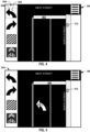
- FIGS. 4 and 5 depict a simplified example of a graphical user interface 300 (e.g., corresponding to marked marking GUI 216 of FIG. 3 ).
- a graphical user interface 300 e.g., corresponding to marked marking GUI 216 of FIG. 3
- an intersection between West Street and North Street is visualized in a graphical map.
- the map can be generated on a display based on survey data 206 and/or map data 136 of FIG. 2 .
- North Street runs vertically in the page while West Street runs in a horizontal direction with respect to the page orientation of FIGS. 4 and 5 .
- a set of marking templates 304 (e.g., corresponding to marking template data 212) is shown along the edge of the graphical map 302.
- the templates 304 include various potential road markings that may be selected in response to a user input.
- the templates include attribute data that define features (e.g., size, color, thickness, etc.) for each selected marking, such as may be user configurable and/or be assigned automatically upon selection.
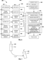
- the system 400 which may be implemented in the computing device on the vehicle (e.g., computing device 22) includes the plurality of sensors that provide the corresponding sensor data 406.
- the sensor data is the same as sensor data in FIG. 2 .
- different sensors and data may be used for mapping and application location determination.
- the sensors may include a GPS sensor 420 and one or more other sensors. In other examples, a full complement of sensors may be utilized.
- the precision localization function 460 is configured to determine vehicle location and orientation based on the fused location data that has been transformed into the vehicle reference frame.
- fused location data derived from multi-modal sensors provides global (absolute) geospatial coordinates as well as local (relative) location information.
- the precision localization function 460 leveraging both absolute and relative location information in the fused location data, a higher level of accuracy can be maintained for the resulting pose data 402 along the path of travel.
- the precision localization function 460 utilizes the survey data 408, which includes the path data 410 and the fiducial data 412.
- the fiducial data 412 can include data identifying a selected subset of fiducials detected by respective sensors along with pose (position and orientation) for its respective fiducial reference frame, which has been transformed into the vehicle reference frame.
- the precision localization function can quantify differences to help determine where each target location is in absolute coordinates with respect to the application tool.
- the precision localization function 460 can implement a fiducial recognition 462 to identify and extract fiducials from the corresponding sensor data (e.g., data 426, 430 and 442).
- the fiducial data 412 further may be used to specify expected fiducial locations.
- the pose of extracted fiducial may be evaluated with the pose of fiducials specified in the fidicual data 412.
- a fiducial frame transformation function 464 is programmed to compute a spatial transform relating the pose of each currently sensed fiducial with respect to its previously identified fiducial from the fiducial data 412.
- the transformation can involve translation in one or two directions (e.g., x or y directions) and/or rotation about the Z axis. Examples of approaches that can be utilized to determine the fiducial transformation can include iterative closest point or particle filtering methods. Other mathematical methods may be utilized in other examples.
- the precision localization 460 can use recognized fiducial locations as provided by fiducial data 412 along the vehicle path to generate the pose data 402 with increased precision, since it is adjusted based on detecting differences between fiducial pose in the fiducial data 412 and the weighted and transformed current sensor data 406.
- Fiducial data thus may be provided during the application phase by any number of sensors that can be aggregated based upon the sensor weighting and corresponding transformations provided by the sensor fusion function 450.
- a similar transform may be computed for other sensors.
- the precision localization function 460 can compute the pose of the vehicle and/or tool precisely with respect to fiducials. Since the fiducials are pre-mapped such that their coordinates are known with respect to a reference frame (in fiducial data 412), the precision localization function 460 can, in turn, compute the pose of the application tool with respect to the same reference frame.
- incremental motion of the vehicle may be estimated along the path of travel based on other sensor data acquired by the at least one other sensor along the application path of travel from a first location to a second location.
- the pose of the application tool can be updated based on the estimated incremental motion (estimated from the other sensor data) along the portion of the application path of travel between the first location and the second location.
- the first and second locations correspond to the pose of respective first and second fiducials detected along the path of travel.
- the locations can be geospatial coordinates of the vehicle (or application tool). Each of the locations may be derived from sensor data from a single sensor or from fused sensor data determined (e.g., by sensor fusion function) from multiple sensors, as disclosed herein.
- the corresponding vehicle pose data 402 can be updated accordingly.
- a known pose e.g., having originally recognized a fiducial from the sensor data corresponding to a known fiducial 412
- incremental motion from the starting pose can be estimated from other sensor data (e.g., wheel encoders, steering angle data, accelerometer data, precision odometry, speed sensor data, ground penetrating radar data, gyroscope data, inertial sensor data, LIDAR and the like) that can be compared to the pre-mapped fiducial data and path data 410.
- sensor data e.g., wheel encoders, steering angle data, accelerometer data, precision odometry, speed sensor data, ground penetrating radar data, gyroscope data, inertial sensor data, LIDAR and the like
- GPS data may have uncertainty its location may be augmented from location transformations determined for other sensor data, including fiducials detected from such other sensor data.
- location transformations determined for other sensor data including fiducials detected from such other sensor data.
- computing such incremental motion from a known reference pose may gradually accumulate localization uncertainty errors, as the other sensor data is acquired, including fiducials that are recognized (e.g., by fiducial recognition function 462) along the vehicle path of travel based on corresponding sensor data 406 and spatial transforms computed, such localization uncertainty may be mitigated.
- FIG. 7 illustrates an example of a fiducial transformation that may be implemented.
- a pair of fiducials 480 and 482 is shown.
- a fiducial 480 corresponds to an image that is has been selected and stored in survey data 408 (fiducial data 412 and the path data 408).
- the other fiducial 482 corresponds to the same fiducial captured by sensor data 406 (e.g., camera data 430) as recognized by fiducial recognition function 462.
- Fiducial transformation function 464 can compute a spatial transform from the pose of the second fiducial 482 to pose of the first fiducial 480, such as described above.
- This transformation can include translation and/or rotation of the fiducial corresponding to a distance (e.g., Euclidean or other distance calculation) that the reference frame of image 482 must move to align the references frames of respective fiducials 480 and 482. Since each sensor reference frame is known with respect to the vehicle reference frame, corresponding spatial coordinates of the vehicle can be ascertained as disclosed herein. Similarly, since the application tool's reference frame is known relative to the vehicle reference frame, the corresponding transformation may further be adjusted to ascertain the pose of the application tool reference frame to the same precision.
- a distance e.g., Euclidean or other distance calculation
- FIG. 8 depicts an example of a system 500 that can be implemented to control application of markings to target locations.
- the system 500 for example can be implemented by the system 10 that is integrated into the vehicle 12.
- some of the parts of the system 500 may be integrated into a computing device that is carried on a vehicle whereas others may be implemented in a distributed computing arrangement, such as in a cloud or at a server that may be separate from a vehicle.
- the computing system on a vehicle may employ a wireless network (e.g., via network interface 44) that can access data and functions implemented remotely.
- a wireless network e.g., via network interface 44
- the computing device on the vehicle is configured to implement the controls for using the application tool 502 to apply one or more markings at target locations.
- the system 500 includes a joint-trajectory calculator 510.
- the joint-trajectory calculator is configured to compute joint-trajectory data 512 based on task plan data 506 and tool pose data 514.
- the tool pose data 514 can define the spatial coordinates and orientation of a reference frame of the application tool.
- the tool pose data 514 can be determined by a precision localization function as disclosed herein (see, e.g., FIG. 6 ).
- a tool pose calculator 516 can convert the vehicle pose data 504 into the tool pose data by applying a corresponding transformation based on the known location and orientation of the tool reference plan relative to the vehicle reference frame.
- a task plan generator 518 is configured to generate the task plan data based on the marking data 520 and to a parameter data 522. While the task plan generator is shown as part of the system 500, in some examples, the task plan may be implemented as part of the system 200 of FIG. 3 .
- the marking data 520 corresponds to marking data that is generated by marking generator 204 of FIG. 3 .
- the marking data 520 thus can identify the selected marking, as well as geospatial coordinates and orientation of a marking reference frame thereof.
- the task plan generator 508 can derive a task plan, to define a process path that is executable by the application tool to apply the marking independent of tool location.
- the tool parameter data 522 may specify a distance between a spray head and the surface to apply the marking, a width of the spray at such distance and other parameters to apply the selected marking by the tool 502.
- the task plan data 506 provides a set of instructions that can be executed by the application tool to apply the selected markings in Cartesian space, which is independent of the specified target location and pose of the application tool 502.
- the joint-trajectory calculator 510 thus computes the joint-trajectory data 512 to include corresponding instructions to enable the application tool 502 to apply the selected marking at the target location based on the task plan data 506 and current tool pose data 514.
- the joint-trajectory calculator 510 implements inverse kinematics to map the task plan for the selected marking in Cartesian space into joint space of the application tool.
- the particular mapping and joint-space trajectory will depend on the configuration of the application tool (e.g., number of joints, actuators, length of arms and the like).
- the vehicle is utilized to position the robot to an estimated location, which yields a current tool pose.
- the joint-space trajectory calculator 510 is programmed to employ inverse kinematics on the task plan for the selected marking and based on the actual pose of the application tool 502 to derive a set of instructions (data 512) in the tool's joint space to apply the selected marking at the desired target location within a desired level of precision.
- data 512 data in the tool's joint space to apply the selected marking at the desired target location within a desired level of precision.
- a tool control system 524 thus interprets the joint-space trajectory data 512 into a series of instructions for controlling the application tool 502 for applying the marking at the desired target location.
- the system 500 may include a reachability analyzer 526 to ascertain whether the tool pose is within the zone of reachability provided by the target location in the marking data 520.
- the reachability analyzer 526 can provide guidance to a marking user interface 528.
- the marking user interface 528 can provide guidance (e.g., audible and/or visual guidance) to a user.
- the guidance can indicate whether or not the current tool pose is sufficiently within the zone of reachability to enable the application tool 502 to apply the marking (or at least a substantial portion thereof) at the target location.
- the system 500 is configured to transform the desired marking coordinates to a joint-space trajectory to accommodate the actual pose of the robot relative to target location on the surface. In this way, the robot can be displaced from nominal coordinates yet continue to apply markings precisely where desired on the surface.
- the marking user interface 528 can receive a user input response to instructions from a user input device (e.g., mouse, keypad, touch pad, touch screen or the like).
- the instructions may include confirmation by the user to begin the marking process and apply the selected marking at the target location.
- the marking user interface 528 may be implemented as a GUI that displays a graphical representation of the selected marking at the target location that has been calculated. The user can view the selected marking superimposed on an actual image (e.g., from surface facing camera) that is presented on a display device of the computing device. Based on the image showing where the marking will be applied, the user may make a more informed decision about whether to confirm or reject applying the marking at such location.
- the marking user interface 528 may further present a GUI to enable the user to graphically adjust the target location relative to the displayed camera image in response to a user input. If the user adjusts the target location, an adjusted target location may be provided and stored as the marking data 520. The adjusted target location can in turn be provided to the joint-space trajectory calculator 510 for re-calculating the joint-space trajectory data 512 based on the adjusted target location for the selected marking. In this way, adjustments to the target location of the selected image may be made on the fly to further ensure that the selected marking is applied at a desired location.
- the GUI further may be enable the user to adjust the size of the selected marking or replace the selected marking with a different marking.
- the same process of selecting a marking (new or overpainting) to a apply to a new target location, viewing a graphical representation of the selected marking and providing a user input to adjust the target location for such marking may be used in the field in addition or as an alternative to the predefined marking data.
- FIGS. 9-10 a method in accordance with various aspects of the present disclosure will be better appreciated with reference to FIGS. 9-10 . While, for purposes of simplicity of explanation, the methods are shown and described as executing serially, such methods are not limited by the illustrated order. Some actions could occur in different orders and/or concurrently from that shown. Moreover, not all illustrated features may be required to implement a method.
- the method may be implemented by hardware (e.g., implemented in one or more computers, field programmable gate array (FPGA) and/or by discrete components), firmware and/or software (e.g., machine readable instructions stored in non-transitory media) or a combination of hardware and software.
- FPGA field programmable gate array
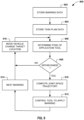
- FIG. 9 depicts an example method 600 for applying a selected marking to a target location.
- the method may be implemented utilizing any of the hardware and/or software disclosed herein with respect to FIGS. 1 - 6 and 8 .
- the method 600 begins at 602 in which marking data is stored (e.g., in non-transitory machine-readable media).
- the marking data e.g., data 34, 202, 520
- a target location can be specified as geospatial coordinates and orientation (e.g., marking codes) with respect to a reference frame of the selected marking.
- corresponding task plan data can also be stored (in memory).
- the task plan data can specify a process plan to create the selected mark with respect to a marking reference frame (part of the marking data stored at 602) and various tool parameters.
- the task plan data can be stored as a vector graphic to describe the path of a corresponding paint head to apply the selected marking in Cartesian (2D or 3D) space.
- the task plan is independent of the target location.
- a respective task plan may be associated with each available marking for a given application tool. If the application tool changes, the task plan may be adapted accordingly.
- a current pose of the application tool is determined.
- the pose of the application tool can be determined (e.g., by location calculator 38, 404) based on sensor data acquired from one or more sensors (e.g., 14, 16, 18, 406) having known positions with respect to the vehicle.
- a determination is made whether the target location is within the zone of reachability for the application tool based on the pose at 606. If the target location is within range, the method proceeds to 610 and a joint-space trajectory is computed.
- the joint-space trajectory can be computed (e.g, by marking control 40, calculator 510) based on the task plan data at 604 and the determined current pose of the application tool provided at 606. The joint-space trajectory enables the application tool to apply the selected markings at the target location provided at 606.
- the method proceeds to 616 in which the vehicle can be moved or the target location adjusted. Based upon the vehicle movement and/or adjustment of target location, the method can return to 606. This process can repeat until determining at 608 that the target location is within the zone of reachability of the application tool.
- the method proceeds to 612 in which the application tool is controlled (e.g., by controller 26, 524) to apply the marking according to the joint-space trajectory associated with the determined pose of the application tool at 606.
- a next marking can be accessed at 614, such as described in the marking data and loaded into memory for applying the next selected marking at its respective next target location.
- the vehicle may be moved at 616 and/or the target location changed at 616 such that the next marking resides within the zone of reachability for the tool. It is understood that the next marking may be identical or different and further may be adjusted based on a selection of the user.
- FIG. 10 is a flow diagram depicting another example method 700 to control applying markings to a surface.
- the method includes storing marking data (e.g., data 34, 202, 520) to specify at least one marking that an application tool is to apply at a target location along an application path of travel for the vehicle.
- marking data e.g., data 34, 202, 520
- geospatial coordinate data is received (e.g., a GPS device 14, 410) to represent a current pose of a vehicle along the application path of travel for the vehicle.
- fiducials are sensed by at least one other sensor (e.g., 16, 18, 424, 428, 432, 436, 440, 444) along the application path of travel.
- the sensed data can be stored in one or more non-transitory machine-readable media.
- fiducial data representing a fiducial coordinate frame for each of the sensed fiducials is determined from such sensor data (e.g., by sensor fusion function 36, 450 or precision localization function) along the application path of travel with respect to a reference coordinate frame.
- a transformation is computed (e.g., by sensor fusion function 36, transformation calculator 464) to correlate the fiducial coordinate frame for each of the sensed fiducials along the application path of travel to a spatial coordinate frame for respective fiducials sensed along a previous survey path of travel.
- the application path of travel by the vehicle is to approximate the survey path of travel (e.g., by driving the vehicle along the same road).
- a pose of the application tool is determined (e.g., by location calculator 38, 404, 460) along the application path of travel based on the transformation and the geospatial coordinate data.
- a joint-space trajectory is computed (e.g, by marking control 40, calculator 510) based on the pose of the application tool and task plan data to enable the application tool to apply the at least one marking at the target location.
- a determination may be made (like at 608 of FIG. 9 ) to condition the computation at 714 depending on whether the target location is within the current reachability of the application tool and/or whether the target location is considered satisfactory by the user.
- the tool is controlled to apply the marking based on the computed joint-space trajectory. The method may be repeated for each marking that is to be applied along the vehicle path of travel, as provided in the marking data.
Landscapes
- Engineering & Computer Science (AREA)
- Physics & Mathematics (AREA)
- General Physics & Mathematics (AREA)
- Multimedia (AREA)
- Remote Sensing (AREA)
- Radar, Positioning & Navigation (AREA)
- Aviation & Aerospace Engineering (AREA)
- Automation & Control Theory (AREA)
- Theoretical Computer Science (AREA)
- Architecture (AREA)
- Structural Engineering (AREA)
- Civil Engineering (AREA)
- Electromagnetism (AREA)
- Computer Vision & Pattern Recognition (AREA)
- Navigation (AREA)
- Control Of Position, Course, Altitude, Or Attitude Of Moving Bodies (AREA)
- Image Analysis (AREA)
- Image Processing (AREA)
- Medicines Containing Material From Animals Or Micro-Organisms (AREA)
- Micro-Organisms Or Cultivation Processes Thereof (AREA)
- Agricultural Chemicals And Associated Chemicals (AREA)
Claims (13)
- Une méthode mise en œuvre par ordinateur comprenant:stocker des données de marquage (34, 202, 520) pour spécifier au moins un marquage sélectionné (214), les données de marquage (34, 202, 520) comprenant une description lisible par machine du marquage sélectionné (214) et un référentiel de coordonnées du marquage (28) pour le marquage sélectionné (214);stocker des données du plan de tâches (506) décrivant un processus exécutable par un outil applicatif (24) pour appliquer le marquage sélectionné (214) sur la base des données de marquage (34, 202, 520) et d'au moins un paramètre de l'outil applicatif (24);déterminer une pose de l'outil applicatif (24); etcalculer une trajectoire de l'espace articulaire de l'outil applicatif (24) sur la base des données du plan de tâches (506) et de la pose de l'outil applicatif (24), la trajectoire de l'espace articulaire fournissant des instructions pour contrôler l'outil applicatif (24) afin d'appliquer le marquage sélectionné (214) à un emplacement cible,caractérisé en ce que le marquage (214) comprend au moins l'un des éléments suivants: un objet graphique à appliquer à une surface à l'emplacement cible, la suppression de la surface à l'emplacement cible, ou la modification de la surface à l'emplacement cible.
- La méthode selon la revendication 1, dans lequel la pose de l'outil applicatif (24) est déterminée par rapport à un véhicule (12) transportant l'outil applicatif (24) sur la base d'au moins l'un d'une image d'un champ de vision acquise par une caméra (18) transportée par le véhicule (12), de coordonnées géospatiales du véhicule (12) et/ou de repères détectés le long d'un trajet de déplacement du véhicule (12).
- La méthode selon la revendication 1, dans lequel le marquage sélectionné (214) est choisi parmi une pluralité de marquages disponibles (214) en réponse à une instruction d'entrée de l'utilisateur.
- La méthode selon la revendication 1, comprenant en outre:générer une représentation graphique du marquage sélectionné (214) superposée sur une image qui comprend un emplacement cible initial; etdéfinir l'emplacement cible en réponse à une instruction d'entrée utilisateur pour accepter l'emplacement cible initial, ou fournir un emplacement cible modifié en réponse à une autre instruction d'entrée utilisateur pour ajuster une position et/ou une taille de la représentation graphique du marquage sélectionné (214) par rapport à l'emplacement cible initial, dans lequel la trajectoire de l'espace articulaire est calculée sur la base des données du plan de tâches (506), de la pose de l'outil applicatif (24) et de l'instruction d'entrée utilisateur.
- La méthode selon la revendication 1, dans lequel les données du plan de tâches (506) décrivent le processus exécutable par l'outil applicatif (24) pour appliquer le marquage sélectionné (214) indépendamment de l'emplacement cible.
- La méthode selon la revendication 1, comprenant en outre l'acquisition, par un dispositif d'imagerie, d'une image d'un champ de vision, et l'utilisation de l'image pour déterminer la position de l'outil applicatif (24) par rapport à un véhicule (12) transportant l'outil applicatif (24).
- La méthode selon la revendication 6, comprenant en outre:pendant que le véhicule (12) est arrêté à un emplacement de départ ou à proximité de celui-ci, générer une représentation graphique du marquage sélectionné (214) superposée à une image de caméra de l'emplacement cible;en réponse à une instruction d'entrée utilisateur confirmant l'application du marquage sélectionné (214) à l'emplacement cible, commander l'outil applicatif (24) pour appliquer le marquage (214) à l'emplacement cible en fonction de la trajectoire dans l'espace articulaire; ouen réponse à l'instruction d'entrée de l'utilisateur rejetant l'application du marquage sélectionné (214) à l'emplacement cible, le procédé comprend en outre:recevoir d'une entrée de l'utilisateur pour ajuster l'emplacement cible à un emplacement cible modifié;calculer une trajectoire modifiée dans l'espace articulaire pour permettre à l'outil applicatif (24) d'appliquer le marquage sélectionné (214) à l'emplacement cible modifié en fonction des données du plan de tâches (506) et de la pose de l'outil applicatif (24); etcontrôler l'outil applicatif (24) pour appliquer le marquage (214) à l'emplacement cible modifié en fonction de la trajectoire modifiée dans l'espace articulaire.
- Un système (10, 12, 32, 100, 200, 400, 500) pour appliquer des marquages (214) sur une surface, le système (10) comprenant:un outil applicatif (24) porté par un véhicule (12) et configuré pour appliquer des marquages (214) sur la surface;un ou plusieurs supports lisibles par machine non transitoires pour stocker des instructions, des données de marquage (34, 202, 520) et des données du plan de tâches (506), les données de marquage (34, 202, 520) décrivant au moins un marquage sélectionné (214), les données de marquage (34, 202, 520) comprenant une description lisible par machine du marquage sélectionné (214) et un référentiel de coordonnées du marquage (28) pour le marquage sélectionné (214), les données du plan de tâches (506) décrivant un processus d'application du marquage sélectionné (214) sur la base d'au moins un paramètre de l'outil applicatif (24);un processeur programmé pour exécuter les instructions pour au moins:déterminer une pose de l'outil applicatif (24) par rapport au véhicule (12); etcalculer une trajectoire dans l'espace articulaire de l'outil applicatif (24) sur la base des données du plan de tâches (506) et de la pose de l'outil applicatif (24), la trajectoire dans l'espace articulaire comprenant un ensemble d'instructions pour permettre à l'outil applicatif (24) d'appliquer le marquage sélectionné (214) à un emplacement cible; etun contrôleur d'outil (26, 524) configuré pour contrôler l'outil applicatif (24) afin d'appliquer le marquage sélectionné (214) à l'emplacement cible en fonction de la trajectoire de l'espace articulaire,caractérisé en ce que le au moins un marquage (214) comprend au moins l'un des éléments suivants: un objet graphique appliqué sur la surface à l'emplacement cible, la suppression de la surface à l'emplacement cible ou la modification de la surface à l'emplacement cible.
- Le système (10, 12, 32, 100, 200, 400, 500) selon la revendication 8, comprenant en outre au moins un capteur (14, 16, 18) pour fournir des données de capteur (104, 106, 108, 110, 112, 114, 116, 11 8, 122, 406, 422, 426, 430, 434, 438, 442, 446) représentant une pose actuelle du véhicule (12) transportant l'outil applicatif (24), dans lequel la pose de l'outil applicatif (24) est déterminée sur la base des données du capteur (104, 106, 108, 110, 112, 114, 116, 118, 122, 406, 422, 426, 430, 434, 438, 442, 446).
- Le système (10, 12, 32, 100, 200, 400, 500) de la revendication 9, dans lequel le au moins un capteur (14, 16, 18, 406) comprend au moins l'un des éléments suivants:un dispositif d'imagerie porté par le véhicule (12) et configuré pour acquérir une image d'un champ de vision qui comprend la surface;un dispositif de système de positionnement global (14, 410) configuré pour fournir des coordonnées géospatiales pour le véhicule (12); et/ouun capteur du marques de cadre configuré pour détecter des marques de cadre le long d'un trajet de déplacement du véhicule (12).
- Le système (10) de la revendication 8, dans lequel le marquage sélectionné est choisi parmi une pluralité de marquages disponibles (214) à appliquer à l'emplacement cible en réponse à une instruction d'entrée de l'utilisateur, et/ou
dans lequel les données du plan de tâches (506) décrivent un processus exécutable par l'outil applicatif (24) pour appliquer le marquage sélectionné (214) indépendamment de l'emplacement cible. - Le système (10, 12, 32, 100, 200, 400, 500) de la revendication 8, comprenant en outre:
un dispositif d'imagerie configuré pour acquérir une image d'un champ de vision qui comprend la surface, dans lequel le processeur est en outre programmé pour exécuter les instructions afin de déterminer la pose de l'outil applicatif (24) par rapport au véhicule (12) transportant l'outil applicatif (24) sur la base de l'image. - Le système (10, 12, 32, 100, 200, 400, 500) de la revendication 12, comprenant en outre un écran (222), dans lequel les instructions sont en outre programmées pour:générer, sur l'écran (222), une représentation graphique du marquage sélectionné (214) superposé sur une image actuelle qui comprend un emplacement cible initial; etdéfinir l'emplacement cible en réponse à une instruction d'entrée utilisateur pour accepter l'emplacement cible initial, ou fournir un emplacement cible modifié en réponse à une autre instruction d'entrée utilisateur ajuster une position et/ou une taille de la représentation graphique du marquage sélectionné (214) par rapport à l'emplacement cible, dans lequel la trajectoire de l'espace articulaire est calculée sur la base des données du plan de tâches (506), de la pose de l'outil applicatif (24) et de l'instruction d'entrée utilisateur.
Applications Claiming Priority (4)
| Application Number | Priority Date | Filing Date | Title |
|---|---|---|---|
| US201762552924P | 2017-08-31 | 2017-08-31 | |
| US201762567621P | 2017-10-03 | 2017-10-03 | |
| PCT/US2018/049118 WO2019046736A1 (fr) | 2017-08-31 | 2018-08-31 | Systèmes et procédés d'application de marquages |
| EP18850421.1A EP3676561B1 (fr) | 2017-08-31 | 2018-08-31 | Systèmes et procédés d'application de marquages |
Related Parent Applications (1)
| Application Number | Title | Priority Date | Filing Date |
|---|---|---|---|
| EP18850421.1A Division EP3676561B1 (fr) | 2017-08-31 | 2018-08-31 | Systèmes et procédés d'application de marquages |
Publications (3)
| Publication Number | Publication Date |
|---|---|
| EP4280177A2 EP4280177A2 (fr) | 2023-11-22 |
| EP4280177A3 EP4280177A3 (fr) | 2024-02-21 |
| EP4280177B1 true EP4280177B1 (fr) | 2025-06-25 |
Family
ID=65526115
Family Applications (2)
| Application Number | Title | Priority Date | Filing Date |
|---|---|---|---|
| EP18850421.1A Active EP3676561B1 (fr) | 2017-08-31 | 2018-08-31 | Systèmes et procédés d'application de marquages |
| EP23201210.4A Active EP4280177B1 (fr) | 2017-08-31 | 2018-08-31 | Systèmes et procédés d'application de marquages |
Family Applications Before (1)
| Application Number | Title | Priority Date | Filing Date |
|---|---|---|---|
| EP18850421.1A Active EP3676561B1 (fr) | 2017-08-31 | 2018-08-31 | Systèmes et procédés d'application de marquages |
Country Status (5)
| Country | Link |
|---|---|
| US (1) | US11550333B2 (fr) |
| EP (2) | EP3676561B1 (fr) |
| DK (2) | DK3676561T3 (fr) |
| FI (2) | FI4280177T3 (fr) |
| WO (1) | WO2019046736A1 (fr) |
Families Citing this family (13)
| Publication number | Priority date | Publication date | Assignee | Title |
|---|---|---|---|---|
| US10304342B2 (en) * | 2016-11-08 | 2019-05-28 | Ge Aviation Systems Llc | Ground-based data acquisition system |
| US11935284B2 (en) * | 2018-08-08 | 2024-03-19 | Technion Research & Development Foundation Limited | Classification with model and localization uncertainty |
| BR112021008098A2 (pt) * | 2018-11-15 | 2021-08-10 | Quantum-Si Incorporated | métodos e composições para o sequenciamento de proteínas |
| US20210383493A1 (en) * | 2020-06-05 | 2021-12-09 | Lyft, Inc. | Systems and methods for creating transportation profiles |
| US12384410B2 (en) | 2021-03-05 | 2025-08-12 | The Research Foundation For The State University Of New York | Task-motion planning for safe and efficient urban driving |
| DE102021117529B3 (de) | 2021-07-07 | 2022-08-18 | Dr. Ing. H.C. F. Porsche Aktiengesellschaft | Verfahren, System und Computerprogrammprodukt zur Verbesserung der Performance von Wahrnehmungsfunktionen für automatisierte Fahrassistenzsysteme |
| EP4426596A4 (fr) * | 2021-11-01 | 2025-11-12 | Autonomous Solutions Inc | Procédé d'utilisation de données de capteurs extéroceptifs sur la base d'un état de véhicule ou d'un état de mission |
| CN114495542B (zh) * | 2021-12-31 | 2023-06-23 | 上海洛轲智能科技有限公司 | 一种辅助驾驶方法、装置及存储介质 |
| CN116414045A (zh) * | 2021-12-31 | 2023-07-11 | 施耐德电气(澳大利亚)有限公司 | 感测节点、感测网络、智能楼宇控制系统和相关联的方法 |
| GB2623287A (en) * | 2022-08-12 | 2024-04-17 | Micropply Ltd | A system for the thermoplastic marking of hard surfaces |
| DK181982B1 (en) * | 2023-09-04 | 2025-05-09 | Tinymobilerobots Aps | A mobile line marking robot with visual odometry |
| CN117649545B (zh) * | 2024-01-30 | 2024-04-12 | 武汉市双桥科技有限公司 | 基于人工智能的喷涂轨迹规划方法及系统 |
| CN120469420B (zh) * | 2025-05-12 | 2025-11-04 | 广东南方电力通信有限公司 | 一种基于智能终端的输电线路航线自动规划与动态调整系统 |
Family Cites Families (31)
| Publication number | Priority date | Publication date | Assignee | Title |
|---|---|---|---|---|
| US5486067A (en) | 1993-12-14 | 1996-01-23 | Pavement Marking Technologies, Inc. | Apparatus and method for marking a surface |
| DE19804195A1 (de) * | 1998-02-03 | 1999-08-05 | Siemens Ag | Bahnplanungsverfahren für eine mobile Einheit zur Flächenbearbeitung |
| US6074693A (en) | 1999-02-22 | 2000-06-13 | Trimble Navigation Limited | Global positioning system controlled paint sprayer |
| US6505995B2 (en) * | 2000-03-21 | 2003-01-14 | Rohm And Haas Company | Road-marking machine |
| CH694807A5 (de) | 2000-10-02 | 2005-07-29 | Udw | Verfahren zur Herstellung von Markierungen sowie ein mobiles Gerät zur Durchführung des Verfahrens. |
| AUPR396501A0 (en) | 2001-03-26 | 2001-04-26 | Edgeroi Pty Ltd | Ground marking apparatus |
| JP2007529017A (ja) * | 2003-05-07 | 2007-10-18 | エベンソ アクティエボラーグ | ビジュアルプレゼンテーションでの大きな表面のマーキング |
| US6951375B2 (en) * | 2003-05-20 | 2005-10-04 | Eastman Kodak Company | Large area marking device and method for printing |
| DE102008017504A1 (de) * | 2008-04-04 | 2010-01-21 | Deutsches Zentrum für Luft- und Raumfahrt e.V. | Vorrichtung zum Auftragen von Fahrbahnmarkierungen |
| US8291855B2 (en) * | 2009-01-16 | 2012-10-23 | Hoerl Jr Jeffrey Joseph | Mobile robot printer for large image reproduction |
| US8174374B2 (en) * | 2009-06-30 | 2012-05-08 | Mitsubishi Electric Research Laboratories, Inc. | Method and system for coding digital information in lane markings using an optical sensor |
| ITUD20110072A1 (it) * | 2011-05-13 | 2012-11-14 | Giacomo Battiston | Dispositivo per la riproduzione di immagini o motivi grafici in genere su superfici, e relativo procedimento |
| US8935057B2 (en) * | 2012-01-17 | 2015-01-13 | LimnTech LLC | Roadway mark data acquisition and analysis apparatus, systems, and methods |
| US9298991B2 (en) | 2012-01-17 | 2016-03-29 | LimnTech LLC | GPS-based machine vision roadway mark locator, inspection apparatus, and marker |
| US9784843B2 (en) * | 2012-01-17 | 2017-10-10 | Limn Tech LLC | Enhanced roadway mark locator, inspection apparatus, and marker |
| US20130310971A1 (en) * | 2012-05-15 | 2013-11-21 | Joseph M. Prouty | Robotic Construction Site Marking Apparatus |
| US20130330467A1 (en) * | 2012-06-12 | 2013-12-12 | Abb Inc. | Method of applying a thin spray-on liner and robotic applicator therefor |
| US9598826B2 (en) * | 2012-10-30 | 2017-03-21 | Capstan Ag Systems, Inc. | Paint spraying system |
| US20140267703A1 (en) * | 2013-03-15 | 2014-09-18 | Robert M. Taylor | Method and Apparatus of Mapping Landmark Position and Orientation |
| EP2973074B1 (fr) * | 2013-03-15 | 2019-04-24 | Carnegie Mellon University | Système robotisé autonome supervisé destiné à l'inspection et au traitement de surface complexe |
| US10104836B2 (en) * | 2014-06-11 | 2018-10-23 | John Paul Jamison | Systems and methods for forming graphical and/or textual elements on land for remote viewing |
| EP3253924B1 (fr) | 2015-02-06 | 2021-09-15 | LimnTech LLC | Système et méthode de marquage de la chaussée |
| US10268202B1 (en) * | 2015-03-30 | 2019-04-23 | DPR Construction | Automated construction scribing devices and methods of use |
| US20170341236A1 (en) * | 2016-05-27 | 2017-11-30 | General Electric Company | Integrated robotic system and method for autonomous vehicle maintenance |
| US10068133B2 (en) * | 2016-01-22 | 2018-09-04 | International Business Machines Corporation | Pavement marking determination |
| US10471595B2 (en) * | 2016-05-31 | 2019-11-12 | Ge Global Sourcing Llc | Systems and methods for control of robotic manipulation |
| FR3050677B1 (fr) * | 2016-04-29 | 2020-02-21 | Les Companions | Procede de traitement d'une surface, et automate correspondant |
| US10417469B2 (en) * | 2016-05-07 | 2019-09-17 | Morgan E. Davidson | Navigation using self-describing fiducials |
| EP3885080B1 (fr) * | 2016-07-04 | 2023-11-29 | Tinymobilerobots APS | Procédé visant à fournir de manière interactive des points de cheminement à un robot mobile destiné à être utilisé dans le marquage d'une figure géométrique sur une surface du sol |
| KR101925289B1 (ko) * | 2017-02-13 | 2018-12-05 | 경희대학교 산학협력단 | 단말 위치/각도 식별 방법 및 장치 |
| US10773174B1 (en) * | 2017-06-21 | 2020-09-15 | Make Ideas, LLC | Automated devices using rotational motion to apply chalk to a surface |
-
2018
- 2018-08-31 EP EP18850421.1A patent/EP3676561B1/fr active Active
- 2018-08-31 WO PCT/US2018/049118 patent/WO2019046736A1/fr not_active Ceased
- 2018-08-31 FI FIEP23201210.4T patent/FI4280177T3/fi active
- 2018-08-31 DK DK18850421.1T patent/DK3676561T3/da active
- 2018-08-31 EP EP23201210.4A patent/EP4280177B1/fr active Active
- 2018-08-31 DK DK23201210.4T patent/DK4280177T3/da active
- 2018-08-31 FI FIEP18850421.1T patent/FI3676561T3/fi active
-
2020
- 2020-02-27 US US16/803,793 patent/US11550333B2/en active Active
Also Published As
| Publication number | Publication date |
|---|---|
| US11550333B2 (en) | 2023-01-10 |
| EP4280177A3 (fr) | 2024-02-21 |
| EP3676561A4 (fr) | 2021-04-28 |
| US20200201350A1 (en) | 2020-06-25 |
| FI4280177T3 (fi) | 2025-08-19 |
| DK3676561T3 (da) | 2023-11-06 |
| CA3074462A1 (fr) | 2019-03-07 |
| FI3676561T3 (fi) | 2023-12-15 |
| WO2019046736A1 (fr) | 2019-03-07 |
| EP3676561A1 (fr) | 2020-07-08 |
| EP4280177A2 (fr) | 2023-11-22 |
| EP3676561B1 (fr) | 2023-10-04 |
| DK4280177T3 (da) | 2025-07-21 |
Similar Documents
| Publication | Publication Date | Title |
|---|---|---|
| EP4280177B1 (fr) | Systèmes et procédés d'application de marquages | |
| US11021075B2 (en) | Autonomous vehicle paletization system | |
| US12559894B2 (en) | Systems and methods to apply surface treatments | |
| EP3635500B1 (fr) | Procédé de navigation pour un véhicule et système associé | |
| US9142063B2 (en) | Positioning system utilizing enhanced perception-based localization | |
| US10217232B2 (en) | Systems and methods for locally aligning map data | |
| Elmakis et al. | Vision-based uav-ugv collaboration for autonomous construction site preparation | |
| US11512975B2 (en) | Method of navigating an unmanned vehicle and system thereof | |
| EP3799618B1 (fr) | Procédé de navigation d'un véhicule et système associé | |
| CN106292697A (zh) | 一种移动设备的室内路径规划与导航方法 | |
| CN112461227A (zh) | 轮式底盘机器人巡检智能化自主导航方法 | |
| KR20130067851A (ko) | 차량 위치 인식 장치 및 방법 | |
| US20220282967A1 (en) | Method and mobile detection unit for detecting elements of infrastructure of an underground line network | |
| CN105556244B (zh) | 用于获取机动车在大地坐标系中的实际位置的方法以及机动车 | |
| CN115855068B (zh) | 一种基于bim的机器人路径自主导航方法及系统 | |
| CN108549383A (zh) | 一种实时多传感器的社区机器人导航方法 | |
| CN109375629A (zh) | 一种巡逻车及其导航避障方法 | |
| KR102475039B1 (ko) | 지도 정보 갱신 장치, 방법 및 시스템 | |
| CN118129730A (zh) | 一种多传感器融合的高程语义地图构建方法 | |
| Park et al. | Vehicle localization using an AVM camera for an automated urban driving | |
| CA3074462C (fr) | Systemes et procedes d'application de marquages | |
| Deusch et al. | Improving localization in digital maps with grid maps | |
| CN211427151U (zh) | 一种应用于封闭场地无人驾驶货运车辆上的自动引导系统 | |
| CN109901589B (zh) | 移动机器人控制方法和装置 | |
| WO2026039457A1 (fr) | Assistance à la réalité augmentée pour plateformes mobiles |
Legal Events
| Date | Code | Title | Description |
|---|---|---|---|
| PUAI | Public reference made under article 153(3) epc to a published international application that has entered the european phase |
Free format text: ORIGINAL CODE: 0009012 |
|
| STAA | Information on the status of an ep patent application or granted ep patent |
Free format text: STATUS: THE APPLICATION HAS BEEN PUBLISHED |
|
| AC | Divisional application: reference to earlier application |
Ref document number: 3676561 Country of ref document: EP Kind code of ref document: P |
|
| AK | Designated contracting states |
Kind code of ref document: A2 Designated state(s): AL AT BE BG CH CY CZ DE DK EE ES FI FR GB GR HR HU IE IS IT LI LT LU LV MC MK MT NL NO PL PT RO RS SE SI SK SM TR |
|
| PUAL | Search report despatched |
Free format text: ORIGINAL CODE: 0009013 |
|
| AK | Designated contracting states |
Kind code of ref document: A3 Designated state(s): AL AT BE BG CH CY CZ DE DK EE ES FI FR GB GR HR HU IE IS IT LI LT LU LV MC MK MT NL NO PL PT RO RS SE SI SK SM TR |
|
| STAA | Information on the status of an ep patent application or granted ep patent |
Free format text: STATUS: REQUEST FOR EXAMINATION WAS MADE |
|
| 17P | Request for examination filed |
Effective date: 20240716 |
|
| RBV | Designated contracting states (corrected) |
Designated state(s): AL AT BE BG CH CY CZ DE DK EE ES FI FR GB GR HR HU IE IS IT LI LT LU LV MC MK MT NL NO PL PT RO RS SE SI SK SM TR |
|
| REG | Reference to a national code |
Free format text: PREVIOUS MAIN CLASS: G06V0020560000 Ref country code: DE Ref legal event code: R079 Ref document number: 602018083103 Country of ref document: DE Ipc: G01B0011140000 |
|
| GRAP | Despatch of communication of intention to grant a patent |
Free format text: ORIGINAL CODE: EPIDOSNIGR1 |
|
| STAA | Information on the status of an ep patent application or granted ep patent |
Free format text: STATUS: GRANT OF PATENT IS INTENDED |
|
| RIC1 | Information provided on ipc code assigned before grant |
Ipc: G05D 1/00 20060101ALI20241231BHEP Ipc: G06V 20/56 20220101ALI20241231BHEP Ipc: G06V 20/58 20220101ALI20241231BHEP Ipc: G06T 7/73 20170101ALI20241231BHEP Ipc: G06T 3/60 20060101ALI20241231BHEP Ipc: G05B 21/02 20060101ALI20241231BHEP Ipc: G05B 19/02 20060101ALI20241231BHEP Ipc: G01B 11/14 20060101AFI20241231BHEP |
|
| INTG | Intention to grant announced |
Effective date: 20250121 |
|
| GRAS | Grant fee paid |
Free format text: ORIGINAL CODE: EPIDOSNIGR3 |
|
| GRAA | (expected) grant |
Free format text: ORIGINAL CODE: 0009210 |
|
| STAA | Information on the status of an ep patent application or granted ep patent |
Free format text: STATUS: THE PATENT HAS BEEN GRANTED |
|
| AC | Divisional application: reference to earlier application |
Ref document number: 3676561 Country of ref document: EP Kind code of ref document: P |
|
| AK | Designated contracting states |
Kind code of ref document: B1 Designated state(s): AL AT BE BG CH CY CZ DE DK EE ES FI FR GB GR HR HU IE IS IT LI LT LU LV MC MK MT NL NO PL PT RO RS SE SI SK SM TR |
|
| P01 | Opt-out of the competence of the unified patent court (upc) registered |
Free format text: CASE NUMBER: APP_23539/2025 Effective date: 20250516 |
|
| REG | Reference to a national code |
Ref country code: GB Ref legal event code: FG4D |
|
| REG | Reference to a national code |
Ref country code: CH Ref legal event code: EP |
|
| REG | Reference to a national code |
Ref country code: DE Ref legal event code: R096 Ref document number: 602018083103 Country of ref document: DE |
|
| REG | Reference to a national code |
Ref country code: CH Ref legal event code: EP |
|
| REG | Reference to a national code |
Ref country code: IE Ref legal event code: FG4D |
|
| REG | Reference to a national code |
Ref country code: DK Ref legal event code: T3 Effective date: 20250714 |
|
| REG | Reference to a national code |
Ref country code: FI Ref legal event code: FGE |
|
| REG | Reference to a national code |
Ref country code: SE Ref legal event code: TRGR |
|
| PGFP | Annual fee paid to national office [announced via postgrant information from national office to epo] |
Ref country code: FI Payment date: 20250825 Year of fee payment: 8 |
|
| PGFP | Annual fee paid to national office [announced via postgrant information from national office to epo] |
Ref country code: DE Payment date: 20250827 Year of fee payment: 8 Ref country code: DK Payment date: 20250825 Year of fee payment: 8 |
|
| REG | Reference to a national code |
Ref country code: LT Ref legal event code: MG9D |
|
| PG25 | Lapsed in a contracting state [announced via postgrant information from national office to epo] |
Ref country code: GR Free format text: LAPSE BECAUSE OF FAILURE TO SUBMIT A TRANSLATION OF THE DESCRIPTION OR TO PAY THE FEE WITHIN THE PRESCRIBED TIME-LIMIT Effective date: 20250926 |
|
| PGFP | Annual fee paid to national office [announced via postgrant information from national office to epo] |
Ref country code: NO Payment date: 20250827 Year of fee payment: 8 |
|
| PG25 | Lapsed in a contracting state [announced via postgrant information from national office to epo] |
Ref country code: BG Free format text: LAPSE BECAUSE OF FAILURE TO SUBMIT A TRANSLATION OF THE DESCRIPTION OR TO PAY THE FEE WITHIN THE PRESCRIBED TIME-LIMIT Effective date: 20250625 |
|
| PGFP | Annual fee paid to national office [announced via postgrant information from national office to epo] |
Ref country code: GB Payment date: 20250827 Year of fee payment: 8 |
|
| PG25 | Lapsed in a contracting state [announced via postgrant information from national office to epo] |
Ref country code: HR Free format text: LAPSE BECAUSE OF FAILURE TO SUBMIT A TRANSLATION OF THE DESCRIPTION OR TO PAY THE FEE WITHIN THE PRESCRIBED TIME-LIMIT Effective date: 20250625 |
|
| PGFP | Annual fee paid to national office [announced via postgrant information from national office to epo] |
Ref country code: FR Payment date: 20250825 Year of fee payment: 8 |
|
| PGFP | Annual fee paid to national office [announced via postgrant information from national office to epo] |
Ref country code: SE Payment date: 20250827 Year of fee payment: 8 |
|
| PG25 | Lapsed in a contracting state [announced via postgrant information from national office to epo] |
Ref country code: RS Free format text: LAPSE BECAUSE OF FAILURE TO SUBMIT A TRANSLATION OF THE DESCRIPTION OR TO PAY THE FEE WITHIN THE PRESCRIBED TIME-LIMIT Effective date: 20250925 |
|
| PG25 | Lapsed in a contracting state [announced via postgrant information from national office to epo] |
Ref country code: LV Free format text: LAPSE BECAUSE OF FAILURE TO SUBMIT A TRANSLATION OF THE DESCRIPTION OR TO PAY THE FEE WITHIN THE PRESCRIBED TIME-LIMIT Effective date: 20250625 |
|
| REG | Reference to a national code |
Ref country code: NL Ref legal event code: MP Effective date: 20250625 |
|
| PG25 | Lapsed in a contracting state [announced via postgrant information from national office to epo] |
Ref country code: NL Free format text: LAPSE BECAUSE OF FAILURE TO SUBMIT A TRANSLATION OF THE DESCRIPTION OR TO PAY THE FEE WITHIN THE PRESCRIBED TIME-LIMIT Effective date: 20250625 |
|
| PG25 | Lapsed in a contracting state [announced via postgrant information from national office to epo] |
Ref country code: PT Free format text: LAPSE BECAUSE OF FAILURE TO SUBMIT A TRANSLATION OF THE DESCRIPTION OR TO PAY THE FEE WITHIN THE PRESCRIBED TIME-LIMIT Effective date: 20251027 |
|
| REG | Reference to a national code |
Ref country code: AT Ref legal event code: MK05 Ref document number: 1806827 Country of ref document: AT Kind code of ref document: T Effective date: 20250625 |
|
| PG25 | Lapsed in a contracting state [announced via postgrant information from national office to epo] |
Ref country code: IS Free format text: LAPSE BECAUSE OF FAILURE TO SUBMIT A TRANSLATION OF THE DESCRIPTION OR TO PAY THE FEE WITHIN THE PRESCRIBED TIME-LIMIT Effective date: 20251025 |
|
| PG25 | Lapsed in a contracting state [announced via postgrant information from national office to epo] |
Ref country code: AT Free format text: LAPSE BECAUSE OF FAILURE TO SUBMIT A TRANSLATION OF THE DESCRIPTION OR TO PAY THE FEE WITHIN THE PRESCRIBED TIME-LIMIT Effective date: 20250625 Ref country code: SM Free format text: LAPSE BECAUSE OF FAILURE TO SUBMIT A TRANSLATION OF THE DESCRIPTION OR TO PAY THE FEE WITHIN THE PRESCRIBED TIME-LIMIT Effective date: 20250625 |
|
| PG25 | Lapsed in a contracting state [announced via postgrant information from national office to epo] |
Ref country code: CZ Free format text: LAPSE BECAUSE OF FAILURE TO SUBMIT A TRANSLATION OF THE DESCRIPTION OR TO PAY THE FEE WITHIN THE PRESCRIBED TIME-LIMIT Effective date: 20250625 |
|
| PG25 | Lapsed in a contracting state [announced via postgrant information from national office to epo] |
Ref country code: PL Free format text: LAPSE BECAUSE OF FAILURE TO SUBMIT A TRANSLATION OF THE DESCRIPTION OR TO PAY THE FEE WITHIN THE PRESCRIBED TIME-LIMIT Effective date: 20250625 |
|
| PG25 | Lapsed in a contracting state [announced via postgrant information from national office to epo] |
Ref country code: EE Free format text: LAPSE BECAUSE OF FAILURE TO SUBMIT A TRANSLATION OF THE DESCRIPTION OR TO PAY THE FEE WITHIN THE PRESCRIBED TIME-LIMIT Effective date: 20250625 |
|
| PG25 | Lapsed in a contracting state [announced via postgrant information from national office to epo] |
Ref country code: SK Free format text: LAPSE BECAUSE OF FAILURE TO SUBMIT A TRANSLATION OF THE DESCRIPTION OR TO PAY THE FEE WITHIN THE PRESCRIBED TIME-LIMIT Effective date: 20250625 |
|
| PG25 | Lapsed in a contracting state [announced via postgrant information from national office to epo] |
Ref country code: ES Free format text: LAPSE BECAUSE OF FAILURE TO SUBMIT A TRANSLATION OF THE DESCRIPTION OR TO PAY THE FEE WITHIN THE PRESCRIBED TIME-LIMIT Effective date: 20250625 |
|
| PG25 | Lapsed in a contracting state [announced via postgrant information from national office to epo] |
Ref country code: RO Free format text: LAPSE BECAUSE OF FAILURE TO SUBMIT A TRANSLATION OF THE DESCRIPTION OR TO PAY THE FEE WITHIN THE PRESCRIBED TIME-LIMIT Effective date: 20250625 |
|
| REG | Reference to a national code |
Ref country code: CH Ref legal event code: H13 Free format text: ST27 STATUS EVENT CODE: U-0-0-H10-H13 (AS PROVIDED BY THE NATIONAL OFFICE) Effective date: 20260324 |
|
| PG25 | Lapsed in a contracting state [announced via postgrant information from national office to epo] |
Ref country code: MC Free format text: LAPSE BECAUSE OF FAILURE TO SUBMIT A TRANSLATION OF THE DESCRIPTION OR TO PAY THE FEE WITHIN THE PRESCRIBED TIME-LIMIT Effective date: 20250625 |
|
| PG25 | Lapsed in a contracting state [announced via postgrant information from national office to epo] |
Ref country code: LU Free format text: LAPSE BECAUSE OF NON-PAYMENT OF DUE FEES Effective date: 20250831 Ref country code: IT Free format text: LAPSE BECAUSE OF FAILURE TO SUBMIT A TRANSLATION OF THE DESCRIPTION OR TO PAY THE FEE WITHIN THE PRESCRIBED TIME-LIMIT Effective date: 20250625 |