EP4280437A1 - Zweiphasiger schrittmotor - Google Patents
Zweiphasiger schrittmotor Download PDFInfo
- Publication number
- EP4280437A1 EP4280437A1 EP22174515.1A EP22174515A EP4280437A1 EP 4280437 A1 EP4280437 A1 EP 4280437A1 EP 22174515 A EP22174515 A EP 22174515A EP 4280437 A1 EP4280437 A1 EP 4280437A1
- Authority
- EP
- European Patent Office
- Prior art keywords
- stator
- rotor
- flexible pcb
- face
- stators
- Prior art date
- Legal status (The legal status is an assumption and is not a legal conclusion. Google has not performed a legal analysis and makes no representation as to the accuracy of the status listed.)
- Pending
Links
Images


Classifications
-
- H—ELECTRICITY
- H02—GENERATION; CONVERSION OR DISTRIBUTION OF ELECTRIC POWER
- H02K—DYNAMO-ELECTRIC MACHINES
- H02K37/00—Motors with rotor rotating step by step and without interrupter or commutator driven by the rotor, e.g. stepping motors
- H02K37/10—Motors with rotor rotating step by step and without interrupter or commutator driven by the rotor, e.g. stepping motors of permanent magnet type
- H02K37/12—Motors with rotor rotating step by step and without interrupter or commutator driven by the rotor, e.g. stepping motors of permanent magnet type with stationary armatures and rotating magnets
- H02K37/125—Magnet axially facing armature
-
- H—ELECTRICITY
- H02—GENERATION; CONVERSION OR DISTRIBUTION OF ELECTRIC POWER
- H02K—DYNAMO-ELECTRIC MACHINES
- H02K1/00—Details of the magnetic circuit
- H02K1/06—Details of the magnetic circuit characterised by the shape, form or construction
- H02K1/12—Stationary parts of the magnetic circuit
-
- H—ELECTRICITY
- H02—GENERATION; CONVERSION OR DISTRIBUTION OF ELECTRIC POWER
- H02K—DYNAMO-ELECTRIC MACHINES
- H02K1/00—Details of the magnetic circuit
- H02K1/06—Details of the magnetic circuit characterised by the shape, form or construction
- H02K1/22—Rotating parts of the magnetic circuit
- H02K1/27—Rotor cores with permanent magnets
- H02K1/2793—Rotors axially facing stators
-
- H—ELECTRICITY
- H02—GENERATION; CONVERSION OR DISTRIBUTION OF ELECTRIC POWER
- H02K—DYNAMO-ELECTRIC MACHINES
- H02K21/00—Synchronous motors having permanent magnets; Synchronous generators having permanent magnets
- H02K21/12—Synchronous motors having permanent magnets; Synchronous generators having permanent magnets with stationary armatures and rotating magnets
- H02K21/24—Synchronous motors having permanent magnets; Synchronous generators having permanent magnets with stationary armatures and rotating magnets with magnets axially facing the armatures, e.g. hub-type cycle dynamos
-
- H—ELECTRICITY
- H02—GENERATION; CONVERSION OR DISTRIBUTION OF ELECTRIC POWER
- H02K—DYNAMO-ELECTRIC MACHINES
- H02K3/00—Details of windings
- H02K3/46—Fastening of windings on the stator or rotor structure
- H02K3/52—Fastening salient pole windings or connections thereto
- H02K3/521—Fastening salient pole windings or connections thereto applicable to stators only
- H02K3/525—Annular coils, e.g. for cores of the claw-pole type
-
- H—ELECTRICITY
- H02—GENERATION; CONVERSION OR DISTRIBUTION OF ELECTRIC POWER
- H02K—DYNAMO-ELECTRIC MACHINES
- H02K2201/00—Specific aspects not provided for in the other groups of this subclass relating to the magnetic circuits
- H02K2201/06—Magnetic cores, or permanent magnets characterised by their skew
-
- H—ELECTRICITY
- H02—GENERATION; CONVERSION OR DISTRIBUTION OF ELECTRIC POWER
- H02K—DYNAMO-ELECTRIC MACHINES
- H02K2201/00—Specific aspects not provided for in the other groups of this subclass relating to the magnetic circuits
- H02K2201/12—Transversal flux machines
-
- H—ELECTRICITY
- H02—GENERATION; CONVERSION OR DISTRIBUTION OF ELECTRIC POWER
- H02K—DYNAMO-ELECTRIC MACHINES
- H02K2203/00—Specific aspects not provided for in the other groups of this subclass relating to the windings
- H02K2203/03—Machines characterised by the wiring boards, i.e. printed circuit boards or similar structures for connecting the winding terminations
Definitions
- the present invention concerns stepper motors, in particular a two-phase stepper motors.
- Stepper motors in particular compact stepper motors, find their application in equipment requiring a high degree of precision.
- the angular rotation of these motors is controlled by means of pulse signals rendering them suitable for a wide variety of electrical equipment.
- Stepper motors are for example commonly found in medical devices, for example dosage devises, as well as in optical equipment, such as microscopes, or cameras.
- stepper motors are known in the art, each striking a different balance between speed and torque.
- VR type stepper motors for example comprise a stator with a number of phases and a rotor, each providing teeth where magnetic forces are concentrated. Angular rotation of the rotor is driven by the attraction of the teeth of the rotor to the opposite magnetized poles on the stator teeth.
- VR-type motors generally do not contain permanent magnets and achieve relatively good speed. However, one of their disadvantages is a suboptimal torque control.
- Permanent magnet (PM) type stepper motors achieve a relatively low speed compared to VR type stepper motors, but a better torque.
- US5982058A for example describes a two-phase stepper motor having a shaft onto which two rotors with a first and a second permanent magnet each having a plurality of north and south pole magnet regions, are rotationally fixed.
- a stator is loosely mounted around the shaft and positioned between the opposing magnets.
- the stator has a disc-shaped yoke and structural poles extending away from the yoke, parallel to the shaft toward the rotors. Electromagnetic wire coils are wrapped around these structural poles, such as to allow the formation of a plurality of electromagnets.
- PM stepper motors with cylindrical rotors are also known in the art.
- the cylindrical rotors are magnetized axially, such that north and south poles alternate around the lateral cylindrical surface of the rotor.
- Portions of the stator and/or an electromagnetic coil are generally arranged around the lateral surface of the cylindrical rotor, such as to interact with the alternatingly polarised lateral surface.
- EP1482626A1 describes a PM stepper motor with a cylindrical rotor assembly having its outer circumference multi-pole magnetized.
- the stator assembly comprises a first stator unit and a second stator unit, each having yokes with a plurality of teeth formed along one side and bent towards the other yoke in the assembled motor.
- the teeth of the two yokes are connected to each other, with interposed spacers.
- the teeth align with the magnetized outer circumference of the cylindrical rotor assembly.
- the invention sets out to find a compact PM stepper motor, preferably of cylindrical shape, which can provide a high torque, as well as a high number of angular positions.
- the stepper motor should be capable of providing higher torque than conventional PM stepper motors of the same or similar size, having the same or similar stepping angles.
- a stepper motor comprising a central shaft, two electromagnetic coils, two ferromagnetic stators each accommodating an electromagnetic coil.
- the central shaft of the motor passes through each of the two coils such as to permit a rotation of said shaft within the stator.
- the electromagnetic coils are preferably copper coils of isolated copper wires.
- the stepper motor further comprises a rotor mounted on said central shaft, such that it is rotationally fixed to the shaft.
- the rotor is positioned between the two stators. The rotational movement of the central axis is driven by the angular displacement of the rotor.
- Each of the two stators comprises an annular portion arranged around one of the coils and at least two teeth extending from the annular portion.
- Each tooth comprises a radial portion extending radially in direction of the central shaft.
- the radial portion of the stator teeth are layered between the electromagnetic coil accommodated in the stator and a face of the rotor.
- the electromagnetic coils accommodated by the stator can fill the substantially entire inner cylindrical volume enclosed by the stator, so as to maximize the volume of coil inside the stator.
- the coils may be wound in form of a cylinder to a diameter which matches the inner diameter of the cylindrical stator.
- the coils may extend from its core to the inner surface of the cylindrical stator wall.
- stator, the stator teeth and the magnetic rotor of this invention allows to optimise the available space for the wound electromagnetic wire on either side of the magnetic rotor.
- the arrangement therefore allows for an increase of the volume of electromagnetic wire, for example copper wire, comprised in the coil in respect of the volume of the magnet.
- This increased ratio contributes to a better torque of the motor.
- the amount of electromagnetic wire in respect of the volume of ferromagnetic material is also increased, further favouring a high torque.
- the arrangement of this invention allows for an increase in the number of windings of the electromagnetic wire in the coil.
- the number of windings of the coil in this invention is entirely independent of the number of teeth, respectively the number of structures providing alternating magnetic poles.
- stator therefore allows for an increase in the packaging weight of the electromagnetic coil windings in the motor.
- the magnitude of the magnetic field strength is directly proportional to the number of windings of the electromagnetic coil.
- the more efficient packaging of the coil in the stepper motor results in an increase of torque.
- the added torque provides for a more powerful stepper motor without having to increase current or increase the size of the motor.
- the teeth of the stator may further comprise a longitudinal portion extending as a continuation of the annular portion of the stator parallel to the central shaft towards the rotor.
- the radial portion of the teeth is substantially perpendicular to the longitudinal portion.
- the inner diameter of the cylindrical volume encompassed by the annular portion of the stator is the same as the inner diameter defined by the longitudinal portion of the stator teeth.
- the inner diameter of the stator is preferably constant over the length of the stator. Moreover, the inner diameter of the stator is preferably also constant in radial direction of the lateral surface. This means that no other structural features of the stator project into the inner cylindrical volume of the stator.
- the two stators are preferably substantially identical.
- the teeth of one stator are preferably angularly offset with respect to the teeth of the other stator.
- the motor further comprises a spacer arranged between the stators for maintaining the two stators at a fixed minimal distance from each other.
- the spacer should be dimensioned to prevent the stators from contacting the face of the rotor.
- the spacer is preferably at least partially made from isolating material, such as a plastic or a composite isolating material.
- the spacer preferably comprises an annular portion.
- the annular portion is arranged around the rotor.
- the spacer is preferably arranged to maintain an angular offset of the teeth of the two stators, such that the angular position of the stators in respect to each other is fixed.
- the spacer may for example have protrusions for engaging between each pair of longitudinal portions of adjacent stator teeth. These protrusions preferably project from either side of the annular portion parallel to the central axis, such that at least one protrusion on either side engages with a compatible recess between two adjacent teeth in one of the stators.
- a stator comprises a stator yoke with a cylindrical portion.
- a stator may further comprise a flange with a hollow cylindrical member having a smaller diameter than the stator yoke.
- the cylindrical flange member is inserted axially into the stator yoke for mounting the coil.
- the central shaft passes axially through the cylindrical flange member.
- the cylindrical flange member may be inserted through the centre of the coil.
- the coil may also be wound about the outer surface of the cylindrical flange member.
- the stator may further comprise a covering member dimensioned to cover the face of the stator opposite the stator teeth. This face, which is the second face of the stator, is facing away from the rotor in the assembled stepper motor.
- the covering member may be connected to the cylindrical flange member.
- a covering member may however also be contained in embodiments of stators without an axially arranged cylindrical flange member.
- the covering member provides a surface through which the motor can be connected to external structures or elements.
- the covering member may for example be arranged for fixing the motor to a support means.
- the covering member may also be arranged for attaching gear boxes and/or adapters to the motor.
- the rotor has two faces, each face being magnetised.
- the radial portions of the stator teeth are arranged between the coils and the rotor, such as to interact with the magnetised faces of the rotor.
- the stators including the teeth and the rotor are arranged sequentially in axial direction of the rotor, the volume of the magnetic rotor of a defined thickness can be maximized to fit the cylindrical shape of the motor.
- This arrangement provides a distinct advantage over PM stepper motors known in the art, in which stator components, for example coils are arranged around the lateral surface of the rotor, thus adding to the outer diameter of the motor.
- the arrangement of the teeth in respect of the rotor in this invention therefore allows to maximise the diameter of the magnetic rotor for a given diameter of the stepper motor.
- the rotor since the ferromagnetic stator teeth interact with the two faces of the rotor, no longitudinal magnetisation along the lateral surface of the rotor is required to drive angular displacement of the rotor. As a result, the rotor may be disc shaped. A disc-shaped rotor further favours a reduced length of the overall motor.
- the rotor comprises two magnetic rotor discs, each discs comprising an even number of disc sectors.
- the discs are magnetised, such that each magnetic south poles and magnetic north poles alternate over the disc sectors over each face of a rotor disc.
- the disc sectors are each axially magnetized over the depth of the rotor disc, such that one pole, for example the south pole, is located on one surface of a disc sector and the other pole, for example the north pole is located on the opposite surface of the disc sector.
- each disc sector of one rotor disk completely superposes a disc sector of the other rotor disc.
- the surfaces of aligned disc sectors may carry the same magnetic pole, or the opposite magnetic pole. This means that a sector of one rotor disc which has an axial N-S polarisation may be aligned with a sector of the other rotor disc which has either an axial N-S or an axial S-N polarisation
- the disc sectors of a magnetic rotor disc may be equal to double the number of radial portions of stator teeth. All disc sectors of the ferromagnetic teeth of a stator should be positioned to interact with disc sectors of the rotor discs, which are each providing the same magnetic pole, i.e. either the south pole or the north pole.
- a central rotor disc is layered between the two magnetic rotor discs.
- the central disc is arranged to fix the magnetic rotor discs in their angular position.
- the central disc is made of a ferromagnetic material, such a steel or iron.
- the ferromagnetic central disc participates in the magnetic field of the magnetic rotor discs. Specifically, the ferromagnetic central disc helps to direct the magnetic flux of the magnets radially towards the central shaft of the rotor.
- Each of the electromagnetic stator coils provides a magnetic phase when a current is flows to it.
- the rotational movement of the two-phase stepper motor is driven by alternating the phases of the stator.
- the coils Upon excitement by an electrical current, the coils temporarily polarize the stator teeth to either the south pole or the north pole.
- the magnetic forces concentrate in the stator teeth, which attract the disc sectors on the face of the rotor disc having the opposite polarization.
- the stepwise the angular displacement of the rotor discs and by extension the central shaft to which the rotor is affixed, can be driven by alternating polarization of the two stators.
- the rotation of the rotor may be driven in one predefined direction. It is also possible that the stepper motor is driven be bidirectional.
- the teeth of the stator may be irregularly spaced. In this embodiment, all radial portions of the teeth of a stator would still be positioned to interact with the disc sectors of a rotor disc each having same magnetic pole, however, at least one of the teeth may slightly overlap with an adjacent disc sector of the opposite pole.
- An irregular spacing between the teeth generates a torque even when no current is temporarily provided to the coils. The so generated torque smoothens the abrupt, stepwise movement of the rotor according to the provision of alternating current. As a result, the rotational speed of the rotor is rendered steadier.
- the stepper motor runs smoother, without stagnation.
- An irregular spacing of the teeth furthermore provides the advantage, that the rotor can be easily turned or adjusted in its position when no current is supplied to the stepper motor.
- a resistance needs to be overcome to move the rotor sections out of their aligned positions. This is not the case when the alignment is incomplete, i.e. if at least some of the teeth are superposed with unequally sized portions of two adjacent disc sectors, as is for example the case with irregularly spaced teeth.
- An incomplete alignment results in a less stable angular position of the rotor, such that this position can be changed smoothly, for example manually by rotating the central shaft, when no current is applied.
- electric tracks for transmitting input / output signals to and optionally from the stepper motor are arranged in one or more flexible printed circuit boards (PCB).
- the tracks may for example be arranged in a front flexible PCB and a rear flexible PCB.
- One or both end portions of a flexible PCBs may have an anulus shape, preferably matching the face is the cylindrical coil on which they are arranged.
- the central shaft passes through the annular end portion of the flexible PCB.
- One or both end portions of the flexible PCBs may also have a curved shape, which preferably match the curvature of the face of the cylindrical coil on which they are arranged.
- a flexible PCB may have different kinds of ends, for example an annulus shaped end portion and another curved end portion.
- Portions of the flexible PCB may be accommodated along the length of a stator into recesses on the cylindrical surface of a stators
- the tracks of the flexible PCB may be electrically connected to each other and/or to the electromagnetic coil.
- Electrical connections may for example be provided by soldering.
- the front flexible PCB may comprise a first end portion, which is electrically connected with a first face of the front coil and with a second end portion, which is arranged on a second face of the rear stator.
- the first sides of the coils are being the sides facing the rotor disc.
- the second sides of the coils are the sides facing away from the rotor discs.
- the second end portion of the front flexible PCB is preferably affixed onto the second face of the rear stator, for example with a suitable adhesive.
- the rear flexible PCB may be configured to provide current to the coils.
- the rear flexible PCB should be electrically connected to the rear coil, the front flexible PCB and to an external power source.
- the rear flexible PCB may comprise a first end portion for electrically connecting the PCB with the first face of the one coil, the rear coil, which is accommodated in a rear stator.
- the second end portion of the rear flex is preferably configured to input and, optionally, to output electrical signals.
- the rear flexible PCB further comprises an intermediate annular portion, suitable for electrically connecting to the front flexible PCB.
- the intermediate portion may be arranged on, preferably fixed onto, a second face of the rear stator, wherein the central shaft passes through said annular portion.
- the intermediate section may for example be arranged on a stator yoke or a suitable covering member, for example a flange disc, covering the second face of the stator.
- the intermediate section should be arranged on or attached to the second face of the rear stator, or its suitable cover, without establishing an electrical connection with the stator.
- the second end of the front flexible PCB is preferably electrically connected to, for example soldered to, the intermediate section of the rear flexible PCT.
- the rear flexible PCB preferably comprises a first longitudinal portion arranged parallel to the central shaft and extending from the first end portion to the intermediate portion of the rear flexible PCB along the outer surface of the rear stator.
- the rear flexible PCB of this embodiment may further comprise a second longitudinal portion folded over the edge of the second face of the rear stator towards the front stator.
- the second longitudinal portion may extend longitudinally along the assembled motor beyond the front stator, such that the free end of the rear flexible PCB is accessible for external electrical connection.
- the assembled stepper motor may be encompassed by an outer sheath.
- the sheath is preferably of hollow cylindrical shape for englobing the stators, the rotor, the spacer, and, optionally, at least partially the electrical wires or the flexible PCBs.
- the two stators, the rotor, and the spacer are completely covered by the outer sheath.
- the outer sheath should preferably made form a protective, durable material, such as stainless steel
- the outer sheath should have a thickness of 0.05 mm to 0.5 mm, or 0.1 mm to 0.3 mm.
- the outer sheath should be water-proof or water-resistant.
- the stepper motor of this invention may further comprise an angular encoder.
- the angular encoder may for example be mounted in on a flexible PCB.
- the encoder may be used to determine the angular velocity, angular acceleration, and/or the angular position of the central shaft, respectively the rotor.
- the stepper motor of this invention may further comprise a magnetic field sensor.
- the magnetic field sensor may be mounted on a flexible PCB.
- the sensor provides the advantage that the field strength can be monitored. This way the current applied to the coils can be adjusted to reach a desired field strength. Monitoring the magnetic field strength provides the additional advantage, that defects in the coils may readily be detected. The coils can therefore be repaired or exchanged to ensure continued performance of the motor.
- the stepper motor of this invention is a compact stepper motor.
- the stepper motor has a maximum outer diameter of 3 mm to 70 mm, preferably of 4.5mm to 22 mm.
- This invention also concerns a method for assembling the stepper motor described herein.
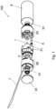
- FIG. 1 A possible embodiment of a stepper motor 100 according to this invention is shown in Figure 1 .
- the figure depicts a schematic exploded view of the motor.
- the embodiment comprised a rotor 4 with a plurality of disc sectors, in the shown example ten disc sectors.
- the regions are magnetized alternatingly with opposing poles, north and south poles.
- the rotor is rotationally fixed to a central shaft 1.
- the central shaft 1 passes along the entire length of the stepper motor 100.
- the central shaft 1 passes axially through a front stator 2A and a rear stator 2B, each comprising a stator yoke 20A, 20B.
- the two stators each accommodate a coil, a front coil, respectively a rear coil.
- the central shaft 1 passes through the core of each coil, such that it can rotate axially inside the coils.
- the stepper motor depicted here comprises a front flexible PCB 6 and a rear flexible PCB 7.
- the stepper motor further comprises stator support members 91, for example bearings.
- the outward faces of the rear 20B and/or the front stator yoke 20A are preferably covered by a covering member 24.
- the covering member may serve as a surface to connect the motor to an external structure.
- the covering member 24 may also function as an interface to gear boxes, adapters, or other units.
- the covering member is preferably disc shaped.
- the covering member may be a supporting flange member, as shown in Figures 1 and 4A .
- the spacer shown here has in central annulus portion and protrusions 51 which are each compatible with area between two adjacent stator teeth.
- the shape of the protrusions 51 is complimentary to the shape of the recesses between the stator teeth 250, such that the spacer 5 matches the shape of both stators. As a result, it fixes the stators in their angular position.
- the spacer 5 is however not limited to the particular shape shown in this figure.
- the number of protrusions of the spacer may for example be less than the number of recesses between the stator teeth. It is also possible to foresee alternative protrusions and recesses in spacer and the stators to fix the angular position of the stators in respect of each other.
- the spacer 5 should be dimensioned such that it creates distance between the stators 2A, 2B, which is sufficiently large to permit layering of the rotor 4 between the stators.
- the spacer 5 should be dimensioned and arranged such that neither of the rotor faces contacts a stator 2A, 2B.
- a gap between the rotor 4 and the stator phases 2A, 2B is important, to avoid that the polarized stator teeth stick to the magnetic rotor and therefore prevent rotation of the motor.
- FIG. 2A shows an exploded view of the rotor, which in this embodiment comprises three discs.
- the two outer discs 41 each comprise magnetised disc sectors 45 of alternating polarities.
- the central disc 42 separated the magnetic discs 41 and is preferably made of magnetic material, such as ferromagnetic material like steel or iron.
- FIG. 2B depicting an assembled rotor 4 fixed on the central shaft 1.
- Disc sectors 45 providing one magnetic pole, for example the north pole, are shown in white, while disc sectors 45 providing the other magnetic pole, for example the south pole, are shown as striped regions.
- the rotor discs may be fixed to the central shaft by means of a rotor support member 47.
- stator coils 3 are electrically connected through flexible PCBs 6, 7, which is a preferred option for providing current to the coils. While the flexible PCBs are used to provide input signals and electrical current to the coils, the flexible PCBs may also be used to receive signals form electric components or sensors positioned in the motor and to output the signals through an external connection.
- the flexible PCBs may for example comprise angular encoders or be connected to angular encoders.
- the flexible PCBs my also comprise or be connected to sensors, for example magnetic field sensors or temperature sensors.
- Figures 3A and 3B show three-dimensional views of a possible embodiment of the front stator 2A with a front flexible PCB 6.
- FIGS. 4A , 4B, and 4C show a possible embodiment of the rear stator.
- the front stator 2A and the rear stator 2B each comprise a stator yoke 20A, 20B.
- the front stator 2A and the rear stator 2B of the shown embodiment furthermore comprise a stator flange with an axial cylindrical flange member 23 around which the electromagnetic coil 3 is placed.
- the stator flanges each also comprise a disc-shaped support member 24 for supporting the mounted the coil.
- the support member 24 acts as a a covering member of the stator.
- cylindrical flange member 23 and the covering member are provided as separate elements, which may optionally be reversibly connected to each other.
- the stator yokes 20A, 20B are substantially cylindrical in shape with a recess 22 along its outer surface for guiding a part a flexible PCB in the assembled motor.
- the stator yokes 20A, 20B each comprise an annular portion 200, which is oriented away from the rotor in the assembled motor, and a plurality of teeth 250, in the shown example 5 teeth for each stator yoke 20A, 20B.
- the teeth of this embodiment have a longitudinal portion 252 extending from the cylindrical lateral surface of the annular portion towards the rotor in the assembled motor.
- the stator teeth 250 further comprise radial portions 251, which each extend perpendicularly from a longitudinal portion 252 towards the geometrical central axis of the stator, respectively toward the central shaft 1 in the assembled motor.
- FIG. 3A and 3B A possible embodiment for a front flexible PCB 6 is also depicted in Figures 3A and 3B .
- the front flexible PCB 6 comprises a first annulus-shaped end portion 61 and a second curved end portion 62. The two end portions are connected by an intermediate longitudinal portion.
- the first end portion 61 is electrically connected to the first face of the electromagnetic coil, which is the face facing the rotor 4 in the assembled motor.
- electrical connections may be established by soldering flexible PCBs to each other or to a coil.
- the end sections may comprise soldering points 99.
- Figure 3B depicts the assembled front stator with the first end of the front flexible PCB soldered onto the first face of the coil.
- the intermediate portion of the front flexible PCB 6 is folded upwardly. This intermediate portion is arranged in longitudinal direction of the stepper motor in direction of the rear stator in the assembled motor.
- the intermediate portion should be dimensioned such that the second end portion 62 of the front flexible PCB can arranged be arranged on the second face of the rear stator, which is the face facing away from the rotor in the assembled motor.
- the rear stator yoke 20B depicted in these Figures 4A , 4B, and 4C is identical to the front stator yoke 20A.
- Both stators 2A, 2B have an axial cylindrical flange member 23, however the outer face of disc-shaped flange member 24 of the rear stator is preferably flat.
- a flat outer face is better suited for arranging of fixing portions of the front and the rear flexible PCB, as is the case in the embodiment depicted in the Figures, in particular Figure 1 .
- the support member 24 of the rear stator yoke also comprises a lateral recess, which may be aligned with the guiding recesses 22 of the stators to guide the longitudinal portions of the flexible PCBs.
- the possible embodiment of the rear flexible PCB 7 shown in Figure 4A to 4C comprises a first annulus-shaped end potion 71, an annulus-shaped intermediate portion 70, and a second end portion 72 for external electrical connection.
- a first longitudinal portion 76 extends between the first end portion 71 and the intermediate portion 70.
- a second longitudinal portion 77 extends between the intermediate portion 70 and the second end portion 72.
- the first end portion 71 is arranged on and electrically connected to the first face of the electromagnetic coil 3 accommodated in the rear stator 2B.
- the first longitudinal portion 76 is folded over the edge of the first face of the coil 3 and guided by a guiding recess 22 along the surface of the rear stator yoke 20B towards its second face, which is oriented away from the rotor in the assembled motor.
- the intermediate portion 70 can then be folded over the edge of the lateral cylindrical surface onto the second face of the rear stator.
- the assembled rear stator 2B with rear flexible PCB 7 is shown in Figure 4C .
- the intermediate portion 70 is arranged on, preferably adhered to, the underside of the stator shown here, which is the second face of the stator 2B.
- the second longitudinal portion 77 and the second end portion 72 are free for further arrangements and connection.
- the second longitudinal portion 77 may provide a required extension to connect the PCB to an external power source.
- the second longitudinal portion 77 may be folded over the edge of the second face of the rear stator to be arranged longitudinally along the cylindrical surface of the assembled motor in direction of the front stator 2A and beyond.
- the so arranged second longitudinal portion 77 may be guided by guide recesses 22 comprised in the outer surfaces of the stator yokes 20A, 20B.
- the motor may be coated by an outer sheath 8.
- the sheath serves to protect the motor from the environment.
- the sheath may be waterproof, or water resistant to protect the electromagnetic components form humidity.
- the outer sheath 8 is preferably of cylindrical shape, matching the shape of the rotor accommodated in it.
- the sheath 8 may comprise covers 95 on either end of its cylindrical shape, such that the stepper motor may be sealed inside the sheath, with only the required wires, cable, or flexible PCB extending outwardly.
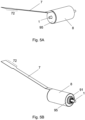
- FIG. 5A and 5B shows a stepper motor contained in a sheath 8 with a cover 95.
- the rear flexible PCB projects outwardly through the sheath to enable electrical connection of the motor.
- a two-phase stepper motor of this invention may be assembled according to the steps set forth in the following.
- the front flexible PCB 6, preferably its first end portion 61, is electrically connected, preferably soldered, a onto a first face of a coil 3.
- the coil 3 is then inserted into the front stator 2A, such that the first face of the coil 3 is adjacent to the radial portions 251 of the stator teeth.
- the coil may be mounted around the hollow cylindrical flange member 23 of a stator yoke 20A, 20B, into which the central shaft 1 is inserted.
- the rear flexible PCB 7 preferably its first end portion 71, is electrically connected, preferably soldered, a onto a first face of the second coil 3.
- the second coil is then inserted into the rear stator, such that the first face of the coil is adjacent to the radial portions of the stator teeth.
- the central shaft 1 is then inserted axially in the stator through the core of the coil accommodated in the front stator.
- the rotor 4 is mounted onto the central shaft 1, such that it is rotationally fixed to the shaft, such that the radial portions of the teeth 251 of the front stator face the rotor, and such that the rotor 4 does not contact said radial portions.
- a spacer member may be temporarily inserted to ensure that a minimal distance between the rotor 4 and the front stator is maintained during their assembly.
- the spacer 5 can then be arranged onto the front stator 2A and around the rotor 4.
- the spacer 5 should be disposed in such a way, that the front flexible PCB 6, in particular its longitudinal portion, protrudes outwardly between the front stator 2A and the spacer 5.
- the rear stator 2B accommodating the other coil 3 onto the shaft, such that the radial portions of the teeth of the rear stator face the rotor, such that the rotor does not contact said radial portions, and such that the rear flexible PCB protrudes outwardly between the rear stator and the spacer.
- the coil may be mounted around the hollow cylindrical flange member 23 of a stator 2A, 2B, into which the central shaft 1 is inserted.
- the flange member 23 should comprise a central opening through which the central shaft 1 may pass.
- the flange member 23 of the rear stator as a support member 24 with a flat disc-shaped outer surface which is suitable for covering the second face of the open cylindrical shape of the rear stator.
- the flat disc-shaped outer surface should be suitable for attaching flexible PCBs.
- the front flexible PCB 6 and the rear flexible PCB 7 are folded towards the second face of the rear stator 2B, which is the face facing away from the rotor 4.
- the second end portion 62 of the front flexible PCB and an intermediate portion 70 of the rear flexible PCB are the arranged on said second face of the rear stator.
- the second face of the rear stator may be the outer surface of the support member 24.
- the intermediate section 70 of the rear flexible PCB is fixed onto the second face of the rear stator, for example by means of an adhesive.
- a portion of the rear flexible PCB extends from the second face of the rear stator 2B, such as to enable electrical connection with an external device.
- the rear flexible PCB 7 may be folded over the edge of the second face of the rear stator 2B, such that the rear flexible PCB 7, preferably the second longitudinal portion of the rear flexible PCB 77, extends longitudinally along the assembled motor beyond the front stator 2A.
- the rear flexible PCB 7 may be guided along the lateral surface of the substantially cylindrical assembled motor by guide recesses 22.
- the so assembled motor may optionally be inserted into the outer sheath 8.
- the portion of the rear flexible PCB 7 which is folded backwards over the rear stator edge to run along the length of the assembled stepper motor is preferably also contained inside the outer sheath 8.
Landscapes
- Engineering & Computer Science (AREA)
- Power Engineering (AREA)
- Windings For Motors And Generators (AREA)
- Insulation, Fastening Of Motor, Generator Windings (AREA)
- Connection Of Motors, Electrical Generators, Mechanical Devices, And The Like (AREA)
- Motor Or Generator Frames (AREA)
Priority Applications (5)
| Application Number | Priority Date | Filing Date | Title |
|---|---|---|---|
| EP22174515.1A EP4280437A1 (de) | 2022-05-20 | 2022-05-20 | Zweiphasiger schrittmotor |
| KR1020247038518A KR20250029779A (ko) | 2022-05-20 | 2023-05-16 | 2상 스테퍼 모터 |
| CN202380041774.6A CN119547313A (zh) | 2022-05-20 | 2023-05-16 | 两相步进马达 |
| JP2024568942A JP2025516897A (ja) | 2022-05-20 | 2023-05-16 | 2相ステッピングモータ |
| PCT/IB2023/055008 WO2023223190A1 (en) | 2022-05-20 | 2023-05-16 | Two-phased stepper motor |
Applications Claiming Priority (1)
| Application Number | Priority Date | Filing Date | Title |
|---|---|---|---|
| EP22174515.1A EP4280437A1 (de) | 2022-05-20 | 2022-05-20 | Zweiphasiger schrittmotor |
Publications (1)
| Publication Number | Publication Date |
|---|---|
| EP4280437A1 true EP4280437A1 (de) | 2023-11-22 |
Family
ID=81750748
Family Applications (1)
| Application Number | Title | Priority Date | Filing Date |
|---|---|---|---|
| EP22174515.1A Pending EP4280437A1 (de) | 2022-05-20 | 2022-05-20 | Zweiphasiger schrittmotor |
Country Status (5)
| Country | Link |
|---|---|
| EP (1) | EP4280437A1 (de) |
| JP (1) | JP2025516897A (de) |
| KR (1) | KR20250029779A (de) |
| CN (1) | CN119547313A (de) |
| WO (1) | WO2023223190A1 (de) |
Citations (10)
| Publication number | Priority date | Publication date | Assignee | Title |
|---|---|---|---|---|
| US4207483A (en) * | 1978-09-01 | 1980-06-10 | Warner Electric Brake & Clutch Co. | Step motor with circumferential stators on opposite sides of disc-like rotor |
| JPS5793088U (de) * | 1980-11-27 | 1982-06-08 | ||
| JPS62185550A (ja) * | 1986-02-07 | 1987-08-13 | Matsushita Electric Works Ltd | ステツプモ−タ |
| US5982058A (en) | 1998-09-02 | 1999-11-09 | Cts Corporation | Two-phase stepper motor |
| EP1482626A1 (de) | 2002-02-14 | 2004-12-01 | Minebea Co., Ltd. | Flachschrittmotor |
| US20050029900A1 (en) * | 2001-12-25 | 2005-02-10 | Keiji Hiramatsu | Generator |
| US20050275295A1 (en) * | 2004-06-14 | 2005-12-15 | Canon Kabushiki Kaisha | Driving device and light amount controller |
| JP2006333610A (ja) * | 2005-05-25 | 2006-12-07 | Canon Inc | 駆動装置及び撮像装置 |
| US20070296312A1 (en) * | 2006-06-26 | 2007-12-27 | Canon Kabushiki Kaisha | Drive apparatus |
| CN212486366U (zh) * | 2020-07-24 | 2021-02-05 | 苏州市优尔特精密机械科技有限公司 | 一种柔性电路音圈电机 |
-
2022
- 2022-05-20 EP EP22174515.1A patent/EP4280437A1/de active Pending
-
2023
- 2023-05-16 JP JP2024568942A patent/JP2025516897A/ja active Pending
- 2023-05-16 KR KR1020247038518A patent/KR20250029779A/ko active Pending
- 2023-05-16 CN CN202380041774.6A patent/CN119547313A/zh active Pending
- 2023-05-16 WO PCT/IB2023/055008 patent/WO2023223190A1/en not_active Ceased
Patent Citations (10)
| Publication number | Priority date | Publication date | Assignee | Title |
|---|---|---|---|---|
| US4207483A (en) * | 1978-09-01 | 1980-06-10 | Warner Electric Brake & Clutch Co. | Step motor with circumferential stators on opposite sides of disc-like rotor |
| JPS5793088U (de) * | 1980-11-27 | 1982-06-08 | ||
| JPS62185550A (ja) * | 1986-02-07 | 1987-08-13 | Matsushita Electric Works Ltd | ステツプモ−タ |
| US5982058A (en) | 1998-09-02 | 1999-11-09 | Cts Corporation | Two-phase stepper motor |
| US20050029900A1 (en) * | 2001-12-25 | 2005-02-10 | Keiji Hiramatsu | Generator |
| EP1482626A1 (de) | 2002-02-14 | 2004-12-01 | Minebea Co., Ltd. | Flachschrittmotor |
| US20050275295A1 (en) * | 2004-06-14 | 2005-12-15 | Canon Kabushiki Kaisha | Driving device and light amount controller |
| JP2006333610A (ja) * | 2005-05-25 | 2006-12-07 | Canon Inc | 駆動装置及び撮像装置 |
| US20070296312A1 (en) * | 2006-06-26 | 2007-12-27 | Canon Kabushiki Kaisha | Drive apparatus |
| CN212486366U (zh) * | 2020-07-24 | 2021-02-05 | 苏州市优尔特精密机械科技有限公司 | 一种柔性电路音圈电机 |
Also Published As
| Publication number | Publication date |
|---|---|
| JP2025516897A (ja) | 2025-05-30 |
| KR20250029779A (ko) | 2025-03-05 |
| WO2023223190A1 (en) | 2023-11-23 |
| CN119547313A (zh) | 2025-02-28 |
Similar Documents
| Publication | Publication Date | Title |
|---|---|---|
| US4306164A (en) | Pulse motor | |
| EP1416619B1 (de) | Hybride elektrische synchronmaschine | |
| US4899072A (en) | Pulse motor | |
| US9991773B2 (en) | Low cost limited rotation rotary actuator | |
| US6940200B2 (en) | Electric drive | |
| AU2002349642A1 (en) | Axial gap type dynamo-electric machine | |
| EP1100188A3 (de) | Elektrische Machine mit Permanentmagnetpolen und steuerbarem Rotorfluss | |
| EP1241771B1 (de) | Bürstenloser Gleichstromvibrationsmotor | |
| KR19990077339A (ko) | 엑시얼 폴 모터 | |
| US6809439B2 (en) | Stepping motor | |
| EP4280437A1 (de) | Zweiphasiger schrittmotor | |
| KR20220024698A (ko) | 로터리 액츄에이터 | |
| CN1905318B (zh) | 驱动装置 | |
| US20220181933A1 (en) | Rotor, motor, and electric power steering device | |
| JP2020162399A (ja) | ブラシレスモータ | |
| EP1858139A2 (de) | Elektrischer Miniaturmotor | |
| JP6798689B2 (ja) | コアレス回転電気機械 | |
| KR101760137B1 (ko) | 스텝핑 모터 | |
| KR20100109693A (ko) | Ipm 타입 모터 | |
| JP3272297B2 (ja) | ステッピングモータ | |
| JP3322910B2 (ja) | ステッピングモータ | |
| SU1538209A1 (ru) | Шаговый двигатель | |
| JP3363786B2 (ja) | マグネットロータ及びpm形ステッピングモータ | |
| RU2093947C1 (ru) | Шаговый электродвигатель | |
| JP2021016217A (ja) | ステッピングモータ |
Legal Events
| Date | Code | Title | Description |
|---|---|---|---|
| PUAI | Public reference made under article 153(3) epc to a published international application that has entered the european phase |
Free format text: ORIGINAL CODE: 0009012 |
|
| STAA | Information on the status of an ep patent application or granted ep patent |
Free format text: STATUS: THE APPLICATION HAS BEEN PUBLISHED |
|
| AK | Designated contracting states |
Kind code of ref document: A1 Designated state(s): AL AT BE BG CH CY CZ DE DK EE ES FI FR GB GR HR HU IE IS IT LI LT LU LV MC MK MT NL NO PL PT RO RS SE SI SK SM TR |
|
| STAA | Information on the status of an ep patent application or granted ep patent |
Free format text: STATUS: REQUEST FOR EXAMINATION WAS MADE |
|
| 17P | Request for examination filed |
Effective date: 20240514 |
|
| RBV | Designated contracting states (corrected) |
Designated state(s): AL AT BE BG CH CY CZ DE DK EE ES FI FR GB GR HR HU IE IS IT LI LT LU LV MC MK MT NL NO PL PT RO RS SE SI SK SM TR |
|
| RAP1 | Party data changed (applicant data changed or rights of an application transferred) |
Owner name: FAULHABER SA |
|
| STAA | Information on the status of an ep patent application or granted ep patent |
Free format text: STATUS: EXAMINATION IS IN PROGRESS |
|
| 17Q | First examination report despatched |
Effective date: 20260224 |