EP4280772A1 - Verfahren zum senden oder empfangen von pusch in einem drahtloskommunikationssystem und vorrichtung dafür - Google Patents
Verfahren zum senden oder empfangen von pusch in einem drahtloskommunikationssystem und vorrichtung dafür Download PDFInfo
- Publication number
- EP4280772A1 EP4280772A1 EP22739706.4A EP22739706A EP4280772A1 EP 4280772 A1 EP4280772 A1 EP 4280772A1 EP 22739706 A EP22739706 A EP 22739706A EP 4280772 A1 EP4280772 A1 EP 4280772A1
- Authority
- EP
- European Patent Office
- Prior art keywords
- information
- rrc
- resource
- multiple beams
- pusch
- Prior art date
- Legal status (The legal status is an assumption and is not a legal conclusion. Google has not performed a legal analysis and makes no representation as to the accuracy of the status listed.)
- Pending
Links
- 238000000034 method Methods 0.000 title claims abstract description 174
- 238000004891 communication Methods 0.000 title claims abstract description 102
- 230000005540 biological transmission Effects 0.000 claims abstract description 86
- 230000015654 memory Effects 0.000 claims description 60
- 238000001514 detection method Methods 0.000 claims description 15
- 238000012545 processing Methods 0.000 claims description 11
- 238000003860 storage Methods 0.000 claims description 7
- 238000005516 engineering process Methods 0.000 description 28
- 230000006870 function Effects 0.000 description 24
- 230000011664 signaling Effects 0.000 description 17
- 238000010295 mobile communication Methods 0.000 description 11
- 229920002635 polyurethane Polymers 0.000 description 11
- 230000003190 augmentative effect Effects 0.000 description 10
- 230000008569 process Effects 0.000 description 10
- 239000010410 layer Substances 0.000 description 8
- 238000013473 artificial intelligence Methods 0.000 description 6
- 230000000694 effects Effects 0.000 description 5
- 230000008054 signal transmission Effects 0.000 description 5
- 230000008901 benefit Effects 0.000 description 4
- 230000000737 periodic effect Effects 0.000 description 4
- 241000700159 Rattus Species 0.000 description 3
- 230000001174 ascending effect Effects 0.000 description 3
- 230000006399 behavior Effects 0.000 description 3
- 230000004044 response Effects 0.000 description 3
- 238000012546 transfer Methods 0.000 description 3
- 238000003491 array Methods 0.000 description 2
- 230000008859 change Effects 0.000 description 2
- 125000004122 cyclic group Chemical group 0.000 description 2
- 238000010586 diagram Methods 0.000 description 2
- 239000002360 explosive Substances 0.000 description 2
- 230000007774 longterm Effects 0.000 description 2
- 238000012423 maintenance Methods 0.000 description 2
- 238000007726 management method Methods 0.000 description 2
- 238000012544 monitoring process Methods 0.000 description 2
- 239000004984 smart glass Substances 0.000 description 2
- 230000001360 synchronised effect Effects 0.000 description 2
- 230000007704 transition Effects 0.000 description 2
- 102100022734 Acyl carrier protein, mitochondrial Human genes 0.000 description 1
- 102100039341 Atrial natriuretic peptide receptor 2 Human genes 0.000 description 1
- 101000678845 Homo sapiens Acyl carrier protein, mitochondrial Proteins 0.000 description 1
- 101000961040 Homo sapiens Atrial natriuretic peptide receptor 2 Proteins 0.000 description 1
- 101000741965 Homo sapiens Inactive tyrosine-protein kinase PRAG1 Proteins 0.000 description 1
- 102100038659 Inactive tyrosine-protein kinase PRAG1 Human genes 0.000 description 1
- 230000004888 barrier function Effects 0.000 description 1
- 230000002457 bidirectional effect Effects 0.000 description 1
- 230000036772 blood pressure Effects 0.000 description 1
- 239000000969 carrier Substances 0.000 description 1
- 230000001413 cellular effect Effects 0.000 description 1
- 230000001684 chronic effect Effects 0.000 description 1
- 238000013461 design Methods 0.000 description 1
- 230000004069 differentiation Effects 0.000 description 1
- 239000003814 drug Substances 0.000 description 1
- 230000009977 dual effect Effects 0.000 description 1
- 230000005611 electricity Effects 0.000 description 1
- 238000009313 farming Methods 0.000 description 1
- 239000000446 fuel Substances 0.000 description 1
- 230000036541 health Effects 0.000 description 1
- 238000010438 heat treatment Methods 0.000 description 1
- 238000009434 installation Methods 0.000 description 1
- 239000002346 layers by function Substances 0.000 description 1
- 238000013507 mapping Methods 0.000 description 1
- 239000011159 matrix material Substances 0.000 description 1
- 238000012986 modification Methods 0.000 description 1
- 230000004048 modification Effects 0.000 description 1
- 230000006855 networking Effects 0.000 description 1
- 238000005457 optimization Methods 0.000 description 1
- 230000001151 other effect Effects 0.000 description 1
- 238000012913 prioritisation Methods 0.000 description 1
- 238000013468 resource allocation Methods 0.000 description 1
- 238000001228 spectrum Methods 0.000 description 1
- 239000013589 supplement Substances 0.000 description 1
- 230000001960 triggered effect Effects 0.000 description 1
- 238000010200 validation analysis Methods 0.000 description 1
- 238000005406 washing Methods 0.000 description 1
Images




Classifications
-
- H—ELECTRICITY
- H04—ELECTRIC COMMUNICATION TECHNIQUE
- H04W—WIRELESS COMMUNICATION NETWORKS
- H04W72/00—Local resource management
- H04W72/04—Wireless resource allocation
- H04W72/044—Wireless resource allocation based on the type of the allocated resource
- H04W72/046—Wireless resource allocation based on the type of the allocated resource the resource being in the space domain, e.g. beams
-
- H—ELECTRICITY
- H04—ELECTRIC COMMUNICATION TECHNIQUE
- H04W—WIRELESS COMMUNICATION NETWORKS
- H04W72/00—Local resource management
- H04W72/12—Wireless traffic scheduling
- H04W72/1263—Mapping of traffic onto schedule, e.g. scheduled allocation or multiplexing of flows
- H04W72/1268—Mapping of traffic onto schedule, e.g. scheduled allocation or multiplexing of flows of uplink data flows
-
- H—ELECTRICITY
- H04—ELECTRIC COMMUNICATION TECHNIQUE
- H04B—TRANSMISSION
- H04B17/00—Monitoring; Testing
- H04B17/30—Monitoring; Testing of propagation channels
- H04B17/309—Measuring or estimating channel quality parameters
- H04B17/318—Received signal strength
- H04B17/328—Reference signal received power [RSRP]; Reference signal received quality [RSRQ]
-
- H—ELECTRICITY
- H04—ELECTRIC COMMUNICATION TECHNIQUE
- H04B—TRANSMISSION
- H04B7/00—Radio transmission systems, i.e. using radiation field
- H04B7/02—Diversity systems; Multi-antenna system, i.e. transmission or reception using multiple antennas
- H04B7/04—Diversity systems; Multi-antenna system, i.e. transmission or reception using multiple antennas using two or more spaced independent antennas
- H04B7/0404—Diversity systems; Multi-antenna system, i.e. transmission or reception using multiple antennas using two or more spaced independent antennas the mobile station comprising multiple antennas, e.g. to provide uplink diversity
-
- H—ELECTRICITY
- H04—ELECTRIC COMMUNICATION TECHNIQUE
- H04B—TRANSMISSION
- H04B7/00—Radio transmission systems, i.e. using radiation field
- H04B7/02—Diversity systems; Multi-antenna system, i.e. transmission or reception using multiple antennas
- H04B7/04—Diversity systems; Multi-antenna system, i.e. transmission or reception using multiple antennas using two or more spaced independent antennas
- H04B7/06—Diversity systems; Multi-antenna system, i.e. transmission or reception using multiple antennas using two or more spaced independent antennas at the transmitting station
- H04B7/0686—Hybrid systems, i.e. switching and simultaneous transmission
- H04B7/0695—Hybrid systems, i.e. switching and simultaneous transmission using beam selection
- H04B7/06952—Selecting one or more beams from a plurality of beams, e.g. beam training, management or sweeping
-
- H—ELECTRICITY
- H04—ELECTRIC COMMUNICATION TECHNIQUE
- H04W—WIRELESS COMMUNICATION NETWORKS
- H04W24/00—Supervisory, monitoring or testing arrangements
- H04W24/08—Testing, supervising or monitoring using real traffic
-
- H—ELECTRICITY
- H04—ELECTRIC COMMUNICATION TECHNIQUE
- H04W—WIRELESS COMMUNICATION NETWORKS
- H04W72/00—Local resource management
- H04W72/20—Control channels or signalling for resource management
- H04W72/23—Control channels or signalling for resource management in the downlink direction of a wireless link, i.e. towards a terminal
-
- H—ELECTRICITY
- H04—ELECTRIC COMMUNICATION TECHNIQUE
- H04L—TRANSMISSION OF DIGITAL INFORMATION, e.g. TELEGRAPHIC COMMUNICATION
- H04L5/00—Arrangements affording multiple use of the transmission path
- H04L5/003—Arrangements for allocating sub-channels of the transmission path
- H04L5/0048—Allocation of pilot signals, i.e. of signals known to the receiver
-
- H—ELECTRICITY
- H04—ELECTRIC COMMUNICATION TECHNIQUE
- H04W—WIRELESS COMMUNICATION NETWORKS
- H04W72/00—Local resource management
- H04W72/50—Allocation or scheduling criteria for wireless resources
- H04W72/54—Allocation or scheduling criteria for wireless resources based on quality criteria
- H04W72/542—Allocation or scheduling criteria for wireless resources based on quality criteria using measured or perceived quality
-
- H—ELECTRICITY
- H04—ELECTRIC COMMUNICATION TECHNIQUE
- H04W—WIRELESS COMMUNICATION NETWORKS
- H04W76/00—Connection management
- H04W76/20—Manipulation of established connections
- H04W76/27—Transitions between radio resource control [RRC] states
Definitions
- the present disclosure relates to a wireless communication system, and particularly, to a method for transmitting or receiving a physical uplink shared channel (PUSCH), and a device therefor.
- PUSCH physical uplink shared channel
- Mobile communication systems have been developed to provide a voice service while ensuring the activity of a user.
- a voice not only a voice, but also a data service is extended.
- a more advanced mobile communication system is required.
- Requirements for a next-generation mobile communication system should be able to support the acceptance of explosive data traffic, a dramatic increase in the per-user data rate, the acceptance of a significant increase in the number of connected devices, very low end-to-end latency, and high-energy efficiency.
- various technologies are researched, which include dual connectivity, massive multiple input multiple output (MIMO), in-band full duplex, non-orthogonal multiple access (NOMA), super wideband support, device networking, and the like.
- RRC radio resource control
- the present disclosure provides a method of transmitting or receiving an uplink channel (or information/data) without transition from an RRC idle state or an RRC inactive state to a connected state, and a device therefor.
- the present disclosure also provides a method of determining an optimal beam for transmitting or receiving an uplink channel (or information/data) in the RRC idle state or RRC inactive state, and a device therefor.
- the present disclosure also provides a method of efficiently transmitting or receiving infrequent small data in the RRC idle state or RRC inactive state, and a device therefor.
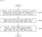
- a method of transmitting a physical uplink shared channel (PUSCH)in a wireless communication system may comprise the steps of: receiving, from a base station, configuration information including information on an uplink resource and information on multiple beams corresponding to the uplink resource; determining an optimal beam among the multiple beams on the basis of an RSRP; and transmitting the PUSCH to the base station on the uplink resource on the basis of a transmission beam corresponding to the optimal beam in an RRC idle state or RRC inactive state.
- configuration information including information on an uplink resource and information on multiple beams corresponding to the uplink resource
- determining an optimal beam among the multiple beams on the basis of an RSRP and transmitting the PUSCH to the base station on the uplink resource on the basis of a transmission beam corresponding to the optimal beam in an RRC idle state or RRC inactive state.
- the information on the multiple beams may include one or more synchronization signal block (SSB) indexes or one or more channel state information-reference signal (CSI-RS) resource indexes.
- SSB synchronization signal block
- CSI-RS channel state information-reference signal
- the method of the present disclosure may further include receiving, from the BS, multiple synchronization signal blocks (SSBs) for determining the optimal beam.
- SSBs synchronization signal blocks
- the method of the present disclosure may further include transmitting, to the BS, a request for the configuration information in an RRC connected state.
- the configuration information may be received in the RRC connected state.
- a UE configured to transmit a physical uplink shared channel (PUSCH) in a wireless communication system, which may include: at least one transceiver; at least one processor; and at least one memory operatively connected to the at least one processor, and storing instructions of performing operations based on being executed based on the at least one processor, in which the operations may include receiving, from a base station (BS), configuration information including information on an uplink resource and information on multiple beams corresponding to the uplink resource, determining an optimal beam among the multiple beams based on a reference signal received power (RSRP), and transmitting, to the BS, the PUSCH on the uplink resource based on a transmission beam corresponding to the optimal beam in an RRC idle state or RRC inactive state.
- BS base station
- RSRP reference signal received power
- the information on the multiple beams may include one or more synchronization signal block (SSB) indexes or one or more channel state information-reference signal (CSI-RS) resource indexes.
- SSB synchronization signal block
- CSI-RS channel state information-reference signal
- the operations may further include receiving, from the BS, multiple synchronization signal blocks (SSBs) for determining the optimal beam.
- SSBs synchronization signal blocks
- the configuration information may be received in the RRC connected state.
- a method of receiving a physical uplink shared channel (PUSCH) in a wireless communication system may include: transmitting, to a UE, configuration information including information on an uplink resource and information on multiple beams corresponding to the uplink resource; performing blind detection based on the multiple beams in a radio resource control (RRC) idle state or an RRC inactive state; and receiving, from the UE, the PUSCH in the uplink resource based on at least one beam among the multiple beams in the RRC idle state or the RRC inactive state.
- RRC radio resource control
- the information on the multiple beams may include one or more synchronization signal block (SSB) indexes or one or more channel state information-reference signal (CSI-RS) resource indexes.
- SSB synchronization signal block
- CSI-RS channel state information-reference signal
- the method of the present disclosure may further include transmitting, to the UE, multiple synchronization signal blocks (SSBs) for determining the optimal beam.
- SSBs synchronization signal blocks
- the method of the present disclosure may further include receiving, from the UE, a request for the configuration information in an RRC connected state.
- the configuration information may be transmitted in the RRC connected state.
- a BS configured to receive a physical uplink shared channel (PUSCH) in a wireless communication system, which may include: at least one transceiver; at least one transceiver; at least one processor; and at least one memory operatively connected to the at least one processor, and storing instructions of performing operations based on being executed based on the at least one processor, in which the operations may include transmitting, to a UE, configuration information including information on an uplink resource and information on multiple beams corresponding to the uplink resource, performing blind detection based on the multiple beams in a radio resource control (RRC) idle state or an RRC inactive state, and receiving, from the UE, the PUSCH in the uplink resource based on at least one beam among the multiple beams in the RRC idle state or the RRC inactive state.
- RRC radio resource control
- the information on the multiple beams may include one or more synchronization signal block (SSB) indexes or one or more channel state information-reference signal (CSI-RS) resource indexes.
- SSB synchronization signal block
- CSI-RS channel state information-reference signal
- the operations may further include transmitting, to the UE, multiple synchronization signal blocks (SSBs) for determining the optimal beam.
- SSBs synchronization signal blocks
- the configuration information may be transmitted in the RRC connected state.
- a processing apparatus configured to control a UE to transmit a physical uplink shared channel (PUSCH) in a wireless communication system, which may include: at least one processor; and at least one memory operatively connected to the at least one processor, and storing instructions of performing operations based on being executed based on the at least one processor, in which the operations may include receiving, from a base station (BS), configuration information including information on an uplink resource and information on multiple beams corresponding to the uplink resource, determining an optimal beam among the multiple beams based on a reference signal received power (RSRP), and transmitting, to the BS, the PUSCH on the uplink resource based on a transmission beam corresponding to the optimal beam in a radio resource control (RRC) idle state or RRC inactive state.
- BS base station
- RSRP reference signal received power
- the operation may include: receiving, from a base station (BS), configuration information including information on an uplink resource and information on multiple beams corresponding to the uplink resource; determining an optimal beam among the multiple beams based on a reference signal received power (RSRP), and transmitting, to the BS, a physical uplink shared channel (PUSCH) on the uplink resource based on a transmission beam corresponding to the optimal beam in a radio resource control (RRC) idle state or RRC inactive state.
- BS base station
- RSRP reference signal received power
- PUSCH physical uplink shared channel
- an uplink channel (or information/data) is transmitted or received without transmission from an RRC idle state or an RRC inactive state to a connected state to improve signaling overhead and UE power consumption.
- an optimal beam for transmitting or receiving an uplink channel is determined in the RRC idle state or RRC inactive state to improve communication reliability.
- infrequent small data can be efficiently transmitted or received in the RRC idle state or RRC inactive state.
- known structures and devices may be omitted or illustrated in a block diagram format based on core functions of each structure and device.
- downlink means communication from the base station to the terminal and uplink (UL) means communication from the terminal to the base station.
- DL downlink
- UL uplink
- a transmitter may be part of the base station, and a receiver may be part of the terminal.
- uplink the transmitter may be part of the terminal and the receiver may be part of the base station.
- the base station may be expressed as a first communication device and the terminal may be expressed as a second communication device.
- a base station may be replaced with terms including a fixed station, a Node B, an evolved-NodeB (eNB), a Next Generation NodeB (gNB), a base transceiver system (BTS), an access point (AP), a network (5G network), an AI system, a road side unit (RSU), a vehicle, a robot, an Unmanned Aerial Vehicle (UAV), an Augmented Reality (AR) device, a Virtual Reality (VR) device, and the like.
- the terminal may be fixed or mobile and may be replaced with terms including a User Equipment (UE), a Mobile Station (MS), a user terminal (UT), a Mobile Subscriber Station (MSS), a Subscriber Station (SS), an Advanced Mobile Station (AMS), a Wireless Terminal (WT), a Machine-Type Communication (MTC) device, a Machine-to-Machine (M2M) device, and a Device-to-Device (D2D) device, the vehicle, the robot, an AI module, the Unmanned Aerial Vehicle (UAV), the Augmented Reality (AR) device, the Virtual Reality (VR) device, and the like.
- UAV Unmanned Aerial Vehicle
- AR Augmented Reality
- VR Virtual Reality
- the following technology may be used in various radio access system including CDMA, FDMA, TDMA, OFDMA, SC-FDMA, and the like.
- the CDMA may be implemented as radio technology such as Universal Terrestrial Radio Access (UTRA) or CDMA2000.
- the TDMA may be implemented as radio technology such as a global system for mobile communications (GSM)/general packet radio service (GPRS)/enhanced data rates for GSM evolution (EDGE).
- GSM global system for mobile communications
- GPRS general packet radio service
- EDGE enhanced data rates for GSM evolution
- the OFDMA may be implemented as radio technology such as Institute of Electrical and Electronics Engineers (IEEE) 802.11 (Wi-Fi), IEEE 802.16 (WiMAX), IEEE 802.20, Evolved UTRA (E-UTRA), or the like.
- the UTRA is a part of Universal Mobile Telecommunications System (UMTS).
- 3rd Generation Partnership Project (3GPP) Long Term Evolution (LTE) is a part of Evolved UMTS (E-UMTS) using the E-UTRA and LTE-Advanced (A)/LTE-A pro is an evolved version of the 3GPP LTE.
- 3GPP NR New Radio or New Radio Access Technology
- 3GPP LTE/LTE-A/LTE-A pro is an evolved version of the 3GPP LTE/LTE-A/LTE-A pro.
- LTE means technology after 3GPP TS 36.xxx Release 8.
- LTE technology after 3GPP TS 36.xxx Release 10 is referred to as the LTE-A
- LTE technology after 3GPP TS 36.xxx Release 13 is referred to as the LTE-A pro.
- the 3GPP NR means technology after TS 38.xxx Release 15.
- the LTE/NR may be referred to as a 3GPP system, "xxx" means a detailed standard document number.
- the LTE/NR may be collectively referred to as the 3GPP system. Matters disclosed in a standard document opened before the disclosure may be referred to for a background art, terms, omissions, etc., used for describing the disclosure. For example, the following documents may be referred to.
- next generation communication As more and more communication devices require larger communication capacity, there is a need for improved mobile broadband communication compared to the existing radio access technology (RAT).
- massive machine type communications MTCs
- MTCs massive machine type communications
- a communication system design considering a service/UE sensitive to reliability and latency is being discussed.
- the introduction of next generation radio access technology considering enhanced mobile broadband communication (eMBB), massive MTC (mMTC), ultra-reliable and low latency communication (URLLC) is discussed, and in the disclosure, the technology is called new RAT for convenience.
- the NR is an expression representing an example of 5G radio access technology (RAT).
- Three major requirement areas of 5G include (1) an enhanced mobile broadband (eMBB) area, (2) a massive machine type communication (mMTC) area and (3) an ultra-reliable and low latency communications (URLLC) area.
- eMBB enhanced mobile broadband
- mMTC massive machine type communication
- URLLC ultra-reliable and low latency communications
- KPI key performance indicator
- eMBB is far above basic mobile Internet access and covers media and entertainment applications in abundant bidirectional tasks, cloud or augmented reality.
- Data is one of key motive powers of 5G, and dedicated voice services may not be first seen in the 5G era.
- voice will be processed as an application program using a data connection simply provided by a communication system.
- Major causes for an increased traffic volume include an increase in the content size and an increase in the number of applications that require a high data transfer rate.
- Streaming service (audio and video), dialogue type video and mobile Internet connections will be used more widely as more devices are connected to the Internet.
- Such many application programs require connectivity always turned on in order to push real-time information and notification to a user.
- cloud storage is a special use case that tows the growth of an uplink data transfer rate.
- 5G is also used for remote business of cloud.
- Entertainment for example, cloud game and video streaming are other key elements which increase a need for the mobile broadband ability. Entertainment is essential in the smartphone and tablet anywhere including high mobility environments, such as a train, a vehicle and an airplane.
- Another use case is augmented reality and information search for entertainment. In this case, augmented reality requires very low latency and an instant amount of data.
- one of the most expected 5G use case relates to a function capable of smoothly connecting embedded sensors in all fields, that is, mMTC.
- mMTC massive machine type
- IoT devices will reach 20.4 billion.
- the industry IoT is one of areas in which 5G performs major roles enabling smart city, asset tracking, smart utility, agriculture and security infra.
- URLLC includes a new service which will change the industry through remote control of major infra and a link having ultra-reliability/low available latency, such as a self-driving vehicle.
- a level of reliability and latency is essential for smart grid control, industry automation, robot engineering, drone control and adjustment.
- 5G may supplement fiber-to-the-home (FTTH) and cable-based broadband (or DOCSIS) as means for providing a stream evaluated from gigabits per second to several hundreds of mega bits per second.
- FTTH fiber-to-the-home
- DOCSIS cable-based broadband
- Such fast speed is necessary to deliver TV with resolution of 4K or more (6K, 8K or more) in addition to virtual reality and augmented reality.
- Virtual reality (VR) and augmented reality (AR) applications include immersive sports games.
- a specific application program may require a special network configuration. For example, in the case of VR game, in order for game companies to minimize latency, a core server may need to be integrated with the edge network server of a network operator.
- An automotive is expected to be an important and new motive power in 5G, along with many use cases for the mobile communication of an automotive. For example, entertainment for a passenger requires a high capacity and a high mobility mobile broadband at the same time. The reason for this is that future users continue to expect a high-quality connection regardless of their location and speed.
- Another use example of the automotive field is an augmented reality dashboard.
- the augmented reality dashboard overlaps and displays information, identifying an object in the dark and notifying a driver of the distance and movement of the object, over a thing seen by the driver through a front window.
- a wireless module enables communication between automotives, information exchange between an automotive and a supported infrastructure, and information exchange between an automotive and other connected devices (e.g., devices accompanied by a pedestrian).
- a safety system guides alternative courses of a behavior so that a driver may drive more safely, thereby reducing a danger of an accident.
- a next step will be a remotely controlled or self-driven vehicle. This requires very reliable, very fast communication between different self-driven vehicles and between an automotive and infra. In the future, a self-driven vehicle may perform all driving activities, and a driver will be focused on things other than traffic, which cannot be identified by an automotive itself.
- Technical requirements of a self-driven vehicle require ultra-low latency and ultra-high speed reliability so that traffic safety is increased up to a level which cannot be achieved by a person.
- a smart city and smart home mentioned as a smart society will be embedded as a high-density radio sensor network.
- the distributed network of intelligent sensors will identify the cost of a city or home and a condition for energy-efficient maintenance.
- a similar configuration may be performed for each home. All of a temperature sensor, a window and heating controller, a burglar alarm and home appliances are wirelessly connected. Many of such sensors are typically a low data transfer rate, low energy and a low cost. However, for example, real-time HD video may be required for a specific type of device for surveillance.
- a smart grid collects information, and interconnects such sensors using digital information and a communication technology so that the sensors operate based on the information.
- the information may include the behaviors of a supplier and consumer, and thus the smart grid may improve the distribution of fuel, such as electricity, in an efficient, reliable, economical, production-sustainable and automated manner.
- the smart grid may be considered to be another sensor network having small latency.
- a health part owns many application programs which reap the benefits of mobile communication.
- a communication system may support remote treatment providing clinical treatment at a distant place. This helps to reduce a barrier for the distance and may improve access to medical services which are not continuously used at remote farming areas. Furthermore, this is used to save life in important treatment and an emergency condition.
- a radio sensor network based on mobile communication may provide remote monitoring and sensors for parameters, such as the heart rate and blood pressure.
- Logistics and freight tracking is an important use case for mobile communication, which enables the tracking inventory and packages anywhere using a location-based information system.
- the logistics and freight tracking use case typically requires a low data speed, but a wide area and reliable location information.
- a new RAT system including NR uses an OFDM transmission scheme or a similar transmission scheme thereto.
- the new RAT system may follow OFDM parameters different from OFDM parameters of LTE.
- the new RAT system may follow numerology of conventional LTE/LTE-A as it is or have a larger system bandwidth (e.g., 100 MHz).
- one cell may support a plurality of numerologies. In other words, UEs that operate with different numerologies may coexist in one cell.
- the numerology corresponds to one subcarrier spacing in a frequency domain.
- Different numerologies may be defined by scaling reference subcarrier spacing to an integer N.
- eLTE eNB The eLTE eNB is the evolution of eNB that supports connectivity to EPC and NGC.
- gNB A node which supports the NR as well as connectivity to NGC.
- New RAN A radio access network which supports either NR or E-UTRA or interfaces with the NGC.
- Network slice is a network created by the operator customized to provide an optimized solution for a specific market scenario which demands specific requirements with end-to-end scope.
- Network function is a logical node within a network infrastructure that has well-defined external interfaces and well-defined functional behavior.
- NG-C A control plane interface used on NG2 reference points between new RAN and NGC.
- NG-U A user plane interface used on NG3 references points between new RAN and NGC.
- Non-standalone NR A deployment configuration where the gNB requires an LTE eNB as an anchor for control plane connectivity to EPC, or requires an eLTE eNB as an anchor for control plane connectivity to NGC.
- Non-standalone E-UTRA A deployment configuration where the eLTE eNB requires a gNB as an anchor for control plane connectivity to NGC.
- User plane gateway A termination point of NG-U interface.
- FIG. 1 illustrates an example of an overall structure of a NR system to which a method proposed in the disclosure is applicable..
- an NG-RAN consists of gNBs that provide an NG-RA user plane (new AS sublayer/PDCP/RLC/MAC/PHY) and control plane (RRC) protocol terminations for a user equipment (UE).
- NG-RA user plane new AS sublayer/PDCP/RLC/MAC/PHY
- RRC control plane
- the gNBs are interconnected with each other by means of an Xn interface.
- the gNBs are also connected to an NGC by means of an NG interface.
- the gNBs are connected to an access and mobility management function (AMF) by means of an N2 interface and to a user plane function (UPF) by means of an N3 interface.
- AMF access and mobility management function
- UPF user plane function
- multiple numerologies may be supported.
- the numerologies may be defined by subcarrier spacing and a CP (Cyclic Prefix) overhead. Spacing between the plurality of subcarriers may be derived by scaling basic subcarrier spacing into an integer N (or ⁇ ).
- N or ⁇
- a numerology to be used may be selected independent of a frequency band.
- OFDM orthogonal frequency division multiplexing
- the NR supports multiple numerologies (or subcarrier spacing (SCS)) for supporting various 5G services. For example, when the SCS is 15 kHz, a wide area in traditional cellular bands is supported and when the SCS is 30 kHz/60 kHz, dense-urban, lower latency, and wider carrier bandwidth are supported, and when the SCS is more than 60 kHz, a bandwidth larger than 24.25 GHz is supported in order to overcome phase noise.
- SCS subcarrier spacing
- NR frequency band is defined as frequency ranges of two types (FR1 and FR2).
- FR1 and FR2 may be configured as shown in Table 2 below. Further, FR2 may mean a millimeter wave (mmW).
- mmW millimeter wave
- ⁇ f max 480 ⁇ 10 3
- N f 4096.
- FIG. 2 illustrates a relation between an uplink frame and a downlink frame in a wireless communication system to which a method proposed in the disclosure is applicable.
- slots are numbered in increasing order of n s ⁇ ⁇ 0 , ... , N subframe slots , ⁇ ⁇ 1 within a subframe and are numbered in increasing order of n s ,f ⁇ ⁇ 0 , ... , N frame slots , ⁇ ⁇ 1 within a radio frame.
- One slot consists of consecutive OFDM symbols of N symb ⁇ , and N symb ⁇ is determined depending on a numerology used and slot configuration.
- the start of slots n s ⁇ in a subframe is aligned in time with the start of OFDM symbols n s ⁇ N symb ⁇ in the same subframe.
- Not all UEs are able to transmit and receive at the same time, and this means that not all OFDM symbols in a downlink slot or an uplink slot are available to be used.
- Table 3 represents the number N symb slot of OFDM symbols per slot, the number N slot frame , ⁇ of slots per radio frame, and the number N slot subframe , ⁇ of slots per subframe in a normal CP.
- Table 4 represents the number of OFDM symbols per slot, the number of slots per radio frame, and the number of slots per subframe in an extended CP. [Table 3] ⁇ N symb slot N slot frame , ⁇ N slot subframe , ⁇ 0 14 10 1 1 14 20 2 2 14 40 4 3 14 80 8 4 14 160 16 [Table 4] ⁇ N symb slot N slot frame , ⁇ N slot subframe , ⁇ 2 12 40 4
- FIG. 3 illustrates an example of a frame structure in a NR system.
- FIG. 3 is merely for convenience of explanation and does not limit the scope of the disclosure.
- a mini-slot may consist of 2, 4, or 7 symbols, or may consist of more symbols or less symbols.
- an antenna port In regard to physical resources in the NR system, an antenna port, a resource grid, a resource element, a resource block, a carrier part, etc. May be considered.
- the antenna port is defined so that a channel over which a symbol on an antenna port is conveyed may be inferred from a channel over which another symbol on the same antenna port is conveyed.
- the two antenna ports may be regarded as being in a quasi co-located or quasi co-location (QC/QCL) relation.
- the large-scale properties may include at least one of delay spread, Doppler spread, frequency shift, average received power, and received timing.
- FIG. 4 illustrates an example of a resource grid supported in a wireless communication system to which a method proposed in the disclosure is applicable.
- a resource grid consists of N RB ⁇ N sc RB subcarriers on a frequency domain, each subframe consisting of 14 ⁇ 2 ⁇ OFDM symbols, but the disclosure is not limited thereto.
- a transmitted signal is described by one or more resource grids, consisting of N RB ⁇ N sc RB subcarriers, and 2 ⁇ N symb ⁇ OFDM symbols, where N RB ⁇ ⁇ N RB max , ⁇ . N RB max , ⁇ denotes a maximum transmission bandwidth and may change not only between numerologies but also between uplink and downlink.
- one resource grid may be configured per numerology ⁇ and antenna port p.
- FIG. 5 illustrates a slot structure of an NR frame to which a method described in the present disclosure is applicable.
- a slot includes a plurality of symbols in a time domain. For example, in a normal CP, one slot includes 7 symbols, and in an extended CP, one slot includes 6 symbols.
- a carrier includes a plurality of subcarriers in a frequency domain.
- a resource block (RB) may be defined as a plurality of consecutive subcarriers (e.g., 12 subcarriers) in the frequency domain.
- a bandwidth part (BWP) may be defined as a plurality of consecutive (physical) RBs ((P)RBs) in the frequency domain, and the BWP may correspond to one numerology (e.g., SCS, CP length, etc.).
- a carrier may include up to N BWPs (e.g., 5 BWPs). Data communication may be performed via an activated BWP, and only one BWP may be activated for one UE.
- Each element in a resource grid may be referred to as a resource element (RE), and one complex symbol may be mapped to each element
- FIG. 6 illustrates examples of a resource grid per antenna port and numerology to which a method described in the present disclosure is applicable.
- the resource element ( k , l ) for the numerology ⁇ and the antenna port p corresponds to a complex value a k , l ⁇ p ⁇ .
- the indices p and ⁇ may be dropped, and as a result, the complex value may be a k , l ⁇ p or a k , l ⁇ .
- Point A serves as a common reference point of a resource block grid and may be obtained as follows.
- - offsetToPointA for PCell downlink represents a frequency offset between the point A and a lowest subcarrier of a lowest resource block that overlaps a SS/PBCH block used by the UE for initial cell selection, and is expressed in units of resource blocks assuming 15 kHz subcarrier spacing for FR1 and 60 kHz subcarrier spacing for FR2;
- - absoluteFrequencyPointA represents frequency-location of the point A expressed as in absolute radio-frequency channel number (ARFCN);
- the common resource blocks are numbered from 0 and upwards in the frequency domain for subcarrier spacing configuration ⁇ .
- n CRB ⁇ ⁇ k N sc RB ⁇
- Physical resource blocks are defined within a bandwidth part (BWP) and are numbered from 0 to N BWP , i size ⁇ 1 , where i is No. Of the BWP.
- BWP bandwidth part
- a relation between the physical resource block n NPRB in BWP i and the common resource block n CRB may be given by the following Equation 2.
- n CRB n PRB + N BWP , i start
- N BWP , i start may be the common resource block where the BWP starts relative to the common resource block 0.
- the NR system may support up to 400 MHz per carrier. If a UE which operates in a wideband carrier operates while continuously turning on a radio frequency (RF) module for all carriers, UE battery consumption may increase. Alternatively, when several use cases (e.g., eMBB, URLLC, Mmtc, V2X, etc.) which operate in one wideband carrier are considered, different numerologies (e.g., sub-carrier spacing) may be supported for each frequency band in the corresponding carrier. Alternatively, a capability for the maximum bandwidth may vary for each UE.
- RF radio frequency
- the BS may instruct the UE to operate only in a partial bandwidth of the wide-band carrier instead of the entire bandwidth, and the corresponding partial bandwidth is referred to as a bandwidth part (BWP).
- BWP bandwidth part
- the BWP is a subset of contiguous common resource blocks defined for a numerology ⁇ i within a bandwidth part i on a carrier, and a numerology (e.g., subcarrier spacing, CP length, slot/mini-slot duration) may be configured.
- the BS may configure one or more BWPs within one carrier configured for the UE.
- some UEs may be moved to other BWPs for load balancing.
- a partial central spectrum of the entire bandwidth may be excluded and both BWPs of the cell may be configured in the same slot by considering frequency domain inter-cell interference cancellation between neighboring cells.
- the BS may configure at least one DL/UL BWP to the UE associated with the wideband carrier, and activate at least one DL/UL BWP among the DL/UL BWP(s) (L1 signaling which is a physical layer control signal, MAC control element (CE) which is an MAC layer control signal, or RRC signaling) and indicate to switch at least one DL/UL BWP to another configured DL/UL BWP (by L1 signaling, MAC CE, or RRC signaling), or configure a timer value, and allow the UE to switch at least one DL/UL BWP to a predetermined DL/UL BWP when the timer expires.
- L1 signaling which is a physical layer control signal
- CE MAC control element
- RRC signaling MAC layer control signal
- the activated DL/UL BWP is specifically referred to as an active DL/UL BWP.
- the UE may not be able to receive a configuration for the DL/UL BWP.
- the DL/UL BWP assumed by the UE is referred to as an initial active DL/UL BWP.
- FIG. 7 illustrates physical channels and general signal transmission used in 3GPP systems.
- the UE receives information from the eNB through Downlink (DL) and the UE transmits information from the eNB through Uplink (UL).
- the information which the eNB and the UE transmit and receive includes data and various control information and there are various physical channels according to a type/use of the information which the eNB and the UE transmit and receive.
- the UE When the UE is powered on or newly enters a cell, the UE performs an initial cell search operation such as synchronizing with the eNB (S701). To this end, the UE may receive a Primary Synchronization Signal (PSS) and a (Secondary Synchronization Signal (SSS) from the eNB and synchronize with the eNB and acquire information such as a cell ID or the like. Thereafter, the UE may receive a Physical Broadcast Channel (PBCH) from the eNB and acquire in-cell broadcast information. Meanwhile, the UE receives a Downlink Reference Signal (DL RS) in an initial cell search step to check a downlink channel status.
- PSS Primary Synchronization Signal
- SSS Secondary Synchronization Signal
- PBCH Physical Broadcast Channel
- DL RS Downlink Reference Signal
- a UE that completes the initial cell search receives a Physical Downlink Control Channel (PDCCH) and a Physical Downlink Control Channel (PDSCH) according to information loaded on the PDCCH to acquire more specific system information (S702).
- PDCCH Physical Downlink Control Channel
- PDSCH Physical Downlink Control Channel
- the UE may perform a Random Access Procedure (RACH) to the eNB (S703 to S706).
- RACH Random Access Procedure
- the UE may transmit a specific sequence to a preamble through a Physical Random Access Channel (PRACH) (S703 and S705) and receive a response message (Random Access Response (RAR) message) for the preamble through the PDCCH and a corresponding PDSCH.
- PRACH Physical Random Access Channel
- RAR Random Access Response
- a Contention Resolution Procedure may be additionally performed (S706).
- the UE that performs the above procedure may then perform PDCCH/PDSCH reception (S707) and Physical Uplink Shared Channel (PUSCH)/Physical Uplink Control Channel (PUCCH) transmission (S708) as a general uplink/downlink signal transmission procedure.
- the UE may receive Downlink Control Information (DCI) through the PDCCH.
- DCI Downlink Control Information
- the DCI may include control information such as resource allocation information for the UE and formats may be differently applied according to a use purpose.
- control information which the UE transmits to the eNB through the uplink or the UE receives from the eNB may include a downlink/uplink ACK/NACK signal, a Channel Quality Indicator (CQI), a Precoding Matrix Index (PMI), a Rank Indicator (RI), and the like.
- the UE may transmit the control information such as the CQI/PMI/RI, etc., through the PUSCH and/or PUCCH.
- New Radio supports the RRC_INACTIVE state in addition to the RRC_IDLE state, and a UE transmitting infrequent (periodic and/or non-periodic) data may be generally instructed by the BS to stay in the RRC_INACTIVE state. Since data transmission in the RRC_INACTIVE state is not supported until Rel-16, the user equipment (UE) must particularly transition the RRC connection to a resume (i.e., the RRC_CONNECTED state) to transmit UL (or Mobile Originated) and/or DL (or Mobile Terminated) data.
- a resume i.e., the RRC_CONNECTED state
- Connection setup for the data transmission and a subsequent return process to the RRC_INACTIVE state are required regardless of the size of data to be transmitted, causing unnecessary power consumption and signaling overhead. This problem becomes particularly serious when the size of the data to be transmitted is small and the transmission frequency is low as follows.
- a method in which the NR UE transmits uplink (UL) data through a preconfigured UL resource (PUR) in the RRC_INACTIVE state may be considered.
- PUR preconfigured UL resource
- a UE supporting UL data transmission in the RRC_INACTIVE state through the PUR may perform PUR transmission in the following order.
- the UE/BS described with reference to FIGS. 9 and 10 may perform at least one of the following operations (1) to (9).
- a method for supporting UL transmission by using PUR resources in the RRC_INACTIVE state in an NR system supporting multi-beams among the overall procedures for the PUR transmission in the RRC_INACTIVE state is proposed. That is, the present disclosure proposes a method of configuring information related to a UL transmission beam of a PUR transmitting UE.
- the present disclosure may include a PUR configuration (i.e., step (1)) of the overall procedure exemplified above, and operations of steps (5) and (6) related thereto.
- the preconfigured UL resource may be mutually replaced with PUR, preconfigured PUSCH resource, configured grant, configured grant type 1, configured grant (CG), CG type 1, CG resource, and the like.
- PUR transmission may mean an operation in which the UE (in the RRC_INACTIVE/RRC_IDLE state) performs UL (e.g., PUSCH) transmission using the PUR, and may include a series of downlink (DL) reception following UL transmission, and UL transmission, and/or may include DL reception accompanying the PUR transmission (PDCCH reception for indicating the availability of a subsequent PUR occasion) or monitoring operation and a subsequent operation accordingly.
- DL downlink
- UL transmission may include a series of downlink (DL) reception following UL transmission, and UL transmission, and/or may include DL reception accompanying the PUR transmission (PDCCH reception for indicating the availability of a subsequent PUR occasion) or monitoring operation and a subsequent operation accordingly.
- the PUR occasion or PUR may be referred to as an uplink resource or a resource for a PUSCH or a resource based on a configured grant.
- performing the PUR transmission may mean transmitting (uplink) channel/signal/data/information through uplink resources (i.e., PUR).
- a PUR UE or a PUR supporting UE may mean a UE that supports UL transmission using the PUR (in the RRC_INACTIVE/RRC_IDLE state), or a PUR supporting UE and instructed and/or configured with the PUR transmission.
- FIG. 8 illustrates a PUR transmission resource configuration
- the PUR may be periodically configured through configuration parameters such as a starting point, a period, and a transmission interval.
- a time/frequency resource capable of periodically repeated PUR transmission is referred to as a PUR occasion in the present disclosure.
- the BS may configure the entire PUR transmission interval in time units (e.g., ms, sec, slot, frame, hyper-frame, etc.) or the number of PUR occasions.
- the setting value may include infinity, and when the setting value is configured to infinity, the UE may continue to perform the PUR transmission unless otherwise instructed by the BS.
- the data transmission in the RRC_INACTIVE state may include data transmission in the RRC_IDLE state or may be replaced with the data transmission in the RRC_IDLE state.
- the UL data transmission method in the RRC_INACTIVE state may include DL reception and/or UL transmission following UL data transmission.
- Method 1 a method (hereinafter, referred to as Method 1) of indicating a UL Tx beam for PUR transmission of the UE by the BS, a method (hereinafter, referred to as Method 2) of allowing the UE to select the UL Tx beam for the PUR transmission, a method (hereinafter, referred to as Method 3) of allowing the UE to select the UL Tx beam for the PUR transmission from among the UL Tx beams indicated by the BS, and a method (hereinafter, referred to as Method 4) of indicating the UL Tx beam only for some PURs by the BS will be described below.
- a slot, a subframe, a frame, etc., mentioned in the embodiments described in the present disclosure may correspond to specific examples of predetermined time units used in the wireless communication system. That is, in applying the methods proposed in the present disclosure, the time unit or the like may be substituted with other time units applied in another wireless communication system, and applied.
- '()' may be interpreted as both excluding the contents in () and including the contents in parentheses. And/or in the present disclosure, '()' may mean a group/emphasis of the element (or content) in parentheses, or mean an abbreviation/full name of the term in front of parentheses, and/or may be English description of the contents in front of parentheses, of course.
- ⁇ /' maybe interpreted as both a case of including the contents distinguished by ⁇ /' (and) and a case of including only some of the distinguished contents (or).
- the PUR supporting UE may request the PUR configuration to the BS in the RRC_CONNECTED state for the PUR transmission in an NR multi-beam situation.
- the BS may configure or reconfigure PUR configuration information (e.g., a form including RRC IE, PUR-Config) requested by the PUR supporting UE through an RRC connection release procedure.
- the RRC connection release procedure may be used to release the PUR configuration including the PUR upon completion of the PUR transmission.
- the PUR configuration may include beam-related information of the PUR.
- the beam-related information of the PUR for the multi-beam operation may be configured in the following methods (Method 1 to Method 4).
- Method 1 - (Method in which the BS indicates the UL Tx beam for the PUR transmission of the UE)
- the method is a method in which the BS indicates a UL transmission (Tx) beam to be used upon the PUR transmission by the PUR supporting UE through the PUR configuration.
- a method of indicating the UL Tx beam by the BS may be a form of configuring or including spatial relation info in an RRC IE (e.g., PUR-Config IE) for the PUR configuration as follows.
- RRC IE e.g., PUR-Config IE
- CSI-RS Resource Indicator CRI
- SSBRI SSB Resource Indicator
- the BS may instruct or recommend to the UE to use a UL Tx beam corresponding to or optimized for the indicated DL beam.
- selection of the final UL beam may be determined by UE implementation.
- the BS configures multiple PURS, and configures the UL Tx beam differently for each PUR to configure the PUR for each beam in the NR multi-beam operation situation.
- SSBRI SSB Resource Indicator
- the UE may perform the PUR transmission through a PUR corresponding to the SSB index selected as the best SSB criterion from the RSRP point of view.
- the BS may receive the UL transmission of the corresponding UE and at the same time, additionally obtain UL Tx beam information used by the corresponding UE by receiving in the SSB beam direction configured for each PUR (s) of the UE to receive or by performing blind detection (BD).
- BD blind detection
- each PUR configuration may include a unique ID.
- the unique ID for distinguishing PUR configurations may be used for prioritization between the PUR configurations. For example, when all or part of the time/frequency domain overlaps between periodically configured PURs, or when the UE cannot simultaneously transmit because different beam directions are indicated, the PUR resource is preferentially selected in order of PUR IDs (e.g., in ascending order of order) to perform the PUR transmission.
- Method 2 - (Method for allowing the UE to select the UL Tx beam for the PUR transmission)
- the method is a method which allows the UE to select the UL Tx beam to be used for the PUR transmission by the PUR supporting UE without instruction by the BS.
- the method is more efficient in terms of using time/frequency resources and has an advantage of having a small signaling overhead, but there may be a disadvantage in that when the PUR transmission should be received in a situation in which the BS may not know the UL Tx beam, a BS BD burden increases.
- the BS may not configure or include spatial relation info in the PUR configuration or in the RRC IE (e.g., PUR-Config IE) for the PUR configuration. That is, when the spatial relation info is not configured or included in the PUR configuration for a specific PUR, the PUR UE may determine the UL Tx beam direction of the corresponding PUR.
- RRC IE e.g., PUR-Config IE
- the BS may instruct the UE to select the UL Tx beam by not configuring the spatial relation info in the PUR configuration.
- the UE may perform the PUR transmission by the UL Tx beam corresponding to the SSB index selected as the best SSB criterion from the RSRP point of view.
- the BS may receive the UL transmission and at the same time, additionally obtain UL Tx beam information by performing the blind detection (BD) on all SSB transmission beam directions for the PUR for which the spatial relation info is not configured.
- BD blind detection
- Method 3 - (Method for allowing the UE to select the UL Tx beam for the PUR transmission among the UL Tx beams indicated by the BS)
- the method is a method which allows the PUR supporting UE to select the UL Tx beam to be used for the PUR transmission among the UL Tx beams indicated by the BS.
- Method 3 has an advantage of being more efficient in terms of time/frequency resource use and smaller signaling overhead than Method 1 in the NR multi-beam operation situation, and may have an advantage of reducing the BS BD burden compared to Method 2.
- the BS may indicate a (candidate) UL Tx beam list or UL Tx beam pool by configuring multiple spatial relation info in the PUR configuration.
- the BS may provide the UE with a (candidate) UL Tx beam list or a pool of UL Tx beams that the UE may select or may be allowed to select by configuring multiple spatial relation info in the PUR configuration corresponding to one PUR. And/or when multiple spatial relation info is configured in one PUR configuration, the UE may perform the PUR transmission by selecting one of UL Tx beams indicated by one of the configured spatial relation info.
- the method may be selecting the UL Tx beam corresponding to the best SSB selected by the UE based on the RSRP.
- the UE may select the best SSB among SSB #1, SSB #2, ..., SSB #M based on SSB RSRP and select the UL Tx beam corresponding thereto, and perform the PUR transmission with a resource indicated by the PUR configuration.
- the base station performs the blind detection (BD) on the SSB beam directions (i.e., SSB #1, SSB #2, ..., SSB #4) included in the PUR configuration of the UE to receive the UL transmission and at the same time, additionally, obtain information on the UL Tx beam selected by the UE in the UL Tx beam list or UL Tx beam pool.
- BD blind detection
- Method 4 - (Method in which the BS indicates the UL Tx beam only for some PURs)
- the method is a method in which the BS configures multiple PURs and indicates the UL Tx beam or UL Tx beam list (or pool) only for some of the multiple PURs. That is, Method 4 may be a method in which the BS selectively configures and applies Methods 1/2/3 for each PUR or for each PUR configuration.
- the BS configures one spatial relation info for a specific PUR or PUR configuration to indicate the UL Tx beam (i.e., Method 1), or does not configure the spatial relation info so that the UE selects the UL Tx beam (i.e., Method 2), or configures multiple spatial relation info so that the UE selects a value from configured values (i.e., Method 3).
- the UE refers to whether the spatial relation info is configure for each PUR or PUR configuration, or the value and number when the spatial relation info is configured, and uses the configured UL Tx beam when one is configured (i.e., Method 1) or the UE selects the UL Tx beam when the spatial relation info is not configured (i.e., Method 2), or selects the UL Tx beam among the configured values when multiple spatial relation info is configured (Method 3) to transmit the PUR.
- the UE may determine the best SSB based on the RSRP among all N SSBs, select a PUR for which the spatial relation info is configured in the corresponding UL Tx beam direction, and perform the PUR transmission.
- the UE may select one of PUR(s) for which L spatial relation info is not configured, and perform the PUR transmission in the UL Tx beam direction corresponding to the best SSB selected by the UE.
- the method for the UE to select one of L PUR(s) for which the spatial relation info is not configured may be either arbitrarily determined by the UE, or determined by a PUR configuration ID (e.g., first selected in ascending order of ID) or by a configured order (e.g., first-configured PUR is preferentially selected).
- the spatial relation info configured in the above example matches the best SSB beam direction determined by the UE
- which resource is to be used may be either arbitrarily determined by the UE, or determined by the PUR configuration ID (e.g., first selected in ascending order of ID) or by the configured order (e.g., first-configured PUR is preferentially selected).
- the UE may first select the PUR in which the spatial relation info is configured. That is, the UE may restrict to (1) preferentially select the UL Tx beam and PUR corresponding to the best SSB based on the SSB RSRP for M SSBs in which the spatial relation info is configured, and (2) select a UL TX beam and PUR corresponding to the best SSB beam among all N SSBs or select one of L PURs in which the spatial relation info is not configured only when even any SSB among M SSBs does not satisfy a specific RSRP threshold the threshold, i.e., only when all qualities of M SSBs are equal to or less than a specific value.
- the UE may have an effect of informing the BS that the quality of the PUR UL Tx beam(s) configured by the BS is equal to or less than a specific threshold.
- the BS may use a procedure of updating an event of receiving the PUR, an event of receiving the PUR (continuously) X times, or the UL TX beam configuration for the UE with the PURs (one of PURs) in which the spatial relation info is not configured for the trigger purpose.
- L PUR(s) in which the spatial relation info is not configured may be used for the purpose of fallback to enable the PUR transmission even when (all) the beam quality of the UL Tx beam direction(s) configured by the BS is equal to or less than a specific threshold.
- a specific threshold there may be advantageous in terms of latency, resource efficiency, etc., against fallback through the RACH procedure.
- FIG. 9 is a flowchart for describing an operation method of a UE proposed in the present disclosure.
- the UE may receive, from the BS, configuration information including information on an uplink resource and information on multiple beams corresponding to the uplink resource.
- the uplink resource may be a resource configured based on a configured grant and/or a resource configured for transmission of small data.
- the uplink resource may be a resource for transmission of the small data based on the configured grant.
- the information on the multiple beams includes one or more synchronization signal block (SSB) indexes (or ids/indicators) and/or one or more channel state information-reference signal (CSI-RS) resource indexes (or ids/indicators).
- SSB synchronization signal block
- CSI-RS channel state information-reference signal
- the information on the multiple beams may include a sequence/bitmap/list/pool constituted by at least one SSB index and/or at least one CSI-RS resource index.
- the information on the multiple beams may include one or more synchronous sounding reference signal (SRS) resource indexes (or ids/indicators).
- the information on the multiple beams may include a sequence/bitmap/list/pool constituted by at least one SRS resource index.
- the information on the multiple beams may include at least one of one or more SSB indexes, one or more CSI-RS resource indexes, and/or one or more SRS resource indexes.
- the information on the multiple beams may include a sequence/bitmap/list/pool constituted by one or more of at least one SSB, at least one CSI-RS resource index, and/or at least one SRS resource index.
- And/or the configuration information may be received in the RRC connected state.
- And/or the UE may transmit a request for the configuration information to the BS in the RRC connected state.
- the UE may receive, from the BS, multiple SSBs and/or multiple CSI-RS resources (or CSI-RSs) for determining an optimal beam.
- the operation of receiving the configuration information in step S901 by the UE in step S901 may be implemented by the apparatuses in FIGS. 11 to 14 .
- one or more processors 102/202 may control one or more memories 104/204 and/or one or more transceivers 106/206 so as to receive the configuration information.
- the UE may determine the optimal beam among the multiple beams based on reference signal received power (RSRP) in step S902. And/or the UE may determine the optimal beam among multiple beams based on a predefined scheme. For example, step S902 may be performed in the RRC idle state or RRC inactive state.
- RSRP reference signal received power
- the operation of determining the optimal beam by the UE in step S901 may be implemented by the apparatuses in FIGS. 11 to 14 .
- one or more processors 102/202 may control one or more memories 104/204 and/or one or more transceivers 106/206 so as to determine the optimal beam.
- the UE may transmit, to the BS, PUSCH (or data/small data/information) in a transmission corresponding to the optimal beam and/or the optimal beam in a radio resource control (RRC) idle state or an RRC inactive state.
- RRC radio resource control
- the UE may transmit the PUSCH in the uplink resource by using the transmission beam corresponding to the optimal beam.
- the transmission beam corresponding to the optimal beam may mean a UL (transmission) beam in the same direction as the optimal beam, and/or a UL (transmission) beam corresponding to the (preconfigured/defined) best beam.
- the UE may transmit the PUSCH in the uplink resource by using the optimal beam.
- UL uplink
- transmission e.g., SRS/SRS resource
- the PUSCH may be replaced with other uplink signals/channels/data/PUSCHs and combinations thereof.
- the PUSCH may be replaced with a physical uplink control channel (PUCCH).
- the PUSCH may be replaced with ⁇ PUCCH and/or PUSCH'.
- the operation of transmitting the PUSCH by the UE in step S903 may be implemented by the apparatuses in FIGS. 11 to 14 .
- one or more processors 102/202 may control one or more memories 104/204 and/or one or more transceivers 106/206 so as to transmit the PUSCH.
- the operation of the UE has been described based on method 3, the UE may operate based on Method 1, Method 2, Method 4, or combinations thereof.
- the operation of the UE described by referring to FIG. 9 is the same as the operations (e.g., Method 1 to Method 4) of the UE described by referring to FIGS. 1 to 8 , so other detailed descriptions will be omitted.
- the signaling and operation may be implemented by the devices (e.g., FIGS. 11 to 14 ) to be described below.
- the signaling and operation may be processed by one or more processors of FIGS. 11 to 14 and the signaling and operation may be stored in memories in the form of an instruction/program (e.g., instruction or executable code) for driving at least one processor of FIGS. 11 to 14 .
- an instruction/program e.g., instruction or executable code
- a processing apparatus configured to control a UE to transmit a physical uplink shared channel (PUSCH) in a wireless communication system may include: at least one processor; and at least one memory operatively connected to the at least one processor, and storing instructions of performing operations based on being executed based on the at least one processor, in which the operations may include receiving, from a base station (BS), configuration information including information on an uplink resource and information on multiple beams corresponding to the uplink resource, determining an optimal beam among the multiple beams based on a reference signal received power (RSRP), and transmitting, to the BS, the PUSCH on the uplink resource based on a transmission beam corresponding to the optimal beam in a radio resource control (RRC) idle state or RRC inactive state.
- BS base station
- RSRP reference signal received power
- the operation may include: receiving, from a base station (BS), configuration information including information on an uplink resource and information on multiple beams corresponding to the uplink resource; determining an optimal beam among the multiple beams based on a reference signal received power (RSRP), and transmitting, to the BS, a physical uplink shared channel (PUSCH) on the uplink resource based on a transmission beam corresponding to the optimal beam in a radio resource control (RRC) idle state or RRC inactive state.
- BS base station
- RSRP reference signal received power
- PUSCH physical uplink shared channel
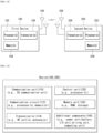
- FIG. 10 is a flowchart for describing an operation method of a base station (BS) proposed by the present disclosure.
- the BS may receive, to the UE, configuration information including information on an uplink resource and information on multiple beams corresponding to the uplink resource.
- the uplink resource may be a resource configured based on a configured grant and/or a resource configured for transmission of small data.
- the uplink resource may be a resource for transmission of the small data based on the configured grant.
- the information on the multiple beams includes one or more synchronization signal block (SSB) indexes (or ids/indicators) and/or one or more channel state information-reference signal (CSI-RS) resource indexes (or ids/indicators).
- SSB synchronization signal block
- CSI-RS channel state information-reference signal
- the information on the multiple beams may include a sequence/bitmap/list/pool constituted by at least one SSB index and/or at least one CSI-RS resource index.
- the information on the multiple beams may include one or more synchronous sounding reference signal (SRS) resource indexes (or ids/indicators).
- the information on the multiple beams may include a sequence/bitmap/list/pool constituted by at least one SRS resource index.
- the information on the multiple beams may include at least one of one or more SSB indexes, one or more CSI-RS resource indexes, and/or one or more SRS resource indexes.
- the information on the multiple beams may include a sequence/bitmap/list/pool constituted by one or more of at least one SSB, at least one CSI-RS resource index, and/or at least one SRS resource index.
- And/or the configuration information may be transmitted in the RRC connected state.
- the BS may receive a request for the configuration information to the BS in the RRC connected state.
- the BS may transmit, toe the UE, multiple SSBs and/or multiple CSI-RS resources (or CSI-RSs) for determining an optimal beam.
- an operation of transmitting the configuration information by the BS in step S1001 may be implemented by the apparatuses in FIGS. 11 to 14 described above.
- one or more processors 102/202 may control one or more memories 104/204 and/or one or more transceivers 106/206 so as to transmit the configuration information.
- the BS may perform blind detection based on multiple beams in a radio resource control (RRC) idle state or an RRC inactive state.
- RRC radio resource control
- the blind detection operation in step S1002 may be performed simultaneously with the PUSCH reception operation in step S1003.
- the BS may receive the PUSCH based on a specific beam by switching multiple beams.
- the operation of performing the blind detection by the BS in step S1002 may be implemented by the apparatuses in FIGS. 11 to 14 described above.
- one or more processors 102/202 may control one or more memories 104/204 and/or one or more transceivers 106/206 so as to perform the blind detection.
- the BS may receive, from the UE, the PUSCH in the uplink resource based on at least one beam among multiple beams in the RRC idle state or RRC inactive state.
- the PUSCH may be replaced with other uplink signals/channels/data/PUSCHs and combinations thereof.
- the PUSCH may be replaced with a physical uplink control channel (PUCCH).
- the PUSCH may be replaced with ⁇ PUCCH and/or PUSCH'.
- the operation of receiving the PUSCH by the BS in step S1003 may be implemented by the apparatuses in FIGS. 11 to 14 described above.
- one or more processors 102/202 may control one or more memories 104/204 and/or one or more transceivers 106/206 so as to receive the PUSCH.
- the BS may operate based on Method 1, Method 2, Method 4, or combinations thereof.
- the operation of the BS described by referring to FIG. 10 is the same as the operations (e.g., Method 1 to Method 4) of the BS described by referring to FIGS. 1 to 9 , so other detailed descriptions will be omitted.
- the signaling and operation may be implemented by the devices (e.g., FIGS. 11 to 14 ) to be described below.
- the signaling and operation may be processed by one or more processors of FIGS. 11 to 14 and the signaling and operation may be stored in memories in the form of an instruction/program (e.g., instruction or executable code) for driving at least one processor of FIGS. 11 to 14 .
- an instruction/program e.g., instruction or executable code
- a processing apparatus configured to control a BS to receive a physical uplink shared channel (PUSCH) in a wireless communication system may include: at least one processor; and at least one memory operatively connected to the at least one processor, and storing instructions of performing operations based on being executed based on the at least one processor, in which the operations may include transmitting, to a UE, configuration information including information on an uplink resource and information on multiple beams corresponding to the uplink resource, performing blind detection based on the multiple beams in a radio resource control (RRC) idle state or RRC inactive state, and receiving, from the UE, the PUSCH in the uplink resource based on at least one beam among the multiple beams in the RRC idle state or RRC inactive state.
- RRC radio resource control
- the operation may include: transmitting, to a UE, configuration information including information on an uplink resource and information on multiple beams corresponding to the uplink resource; performing blind detection based on the multiple beams in a radio resource control (RRC) idle state or RRC inactive state; and receiving, from the UE, the PUSCH in the uplink resource based on at least one beam among the multiple beams in the RRC idle state or RRC inactive state.
- RRC radio resource control
- FIG. 11 illustrates a communication system (1) applied to the disclosure.
- a communication system applied to the disclosure includes wireless devices, Base Stations (BSs), and a network.
- the wireless devices represent devices performing communication using Radio Access Technology (RAT) (e.g., 5G New RAT (NR)) or Long-Term Evolution (LTE)) and may be referred to as communication/radio/SG devices.
- RAT Radio Access Technology
- the wireless devices may include, without being limited to, a robot 100a, vehicles 100b-1 and 100b-2, an extended Reality (XR) device 100c, a hand-held device 100d, a home appliance 100e, an Internet of Things (IoT) device 100f, and an Artificial Intelligence (AI) device/server 400.
- RAT Radio Access Technology
- NR 5G New RAT
- LTE Long-Term Evolution
- the wireless devices may include, without being limited to, a robot 100a, vehicles 100b-1 and 100b-2, an extended Reality (XR) device 100c, a hand-held device 100d, a home appliance 100e, an Internet of Things (I
- the vehicles may include a vehicle having a wireless communication function, an autonomous driving vehicle, and a vehicle capable of performing communication between vehicles.
- the vehicles may include an Unmanned Aerial Vehicle (UAV) (e.g., a drone).
- UAV Unmanned Aerial Vehicle
- the XR device may include an Augmented Reality (AR)/Virtual Reality (VR)/Mixed Reality (MR) device and may be implemented in the form of a Head-Mounted Device (HMD), a Head-Up Display (HUD) mounted in a vehicle, a television, a smartphone, a computer, a wearable device, a home appliance device, a digital signage, a vehicle, a robot, etc.
- the hand-held device may include a smartphone, a smartpad, a wearable device (e.g., a smartwatch or smartglasses), and a computer (e.g., a notebook).
- the home appliance may include a TV, a refrigerator, and a washing machine.
- the IoT device may include a sensor and a smartmeter.
- the BSs and the network may be implemented as wireless devices and a specific wireless device 200a may operate as a BS/network node with respect to other wireless devices.
- the wireless devices 100a to 100f may be connected to the network 300 via the BSs 200.
- An AI technology may be applied to the wireless devices 100a to 100f and the wireless devices 100a to 100f may be connected to the AI server 400 via the network 300.
- the network 300 may be configured using a 3G network, a 4G (e.g., LTE) network, or a 5G (e.g., NR) network.
- the wireless devices 100a to 100f may communicate with each other through the BSs 200/network 300, the wireless devices 100a to 100f may perform direct communication (e.g., sidelink communication) with each other without passing through the BSs/network.
- the vehicles 100b-1 and 100b-2 may perform direct communication (e.g.
- V2V Vehicle-to-Vehicle
- V2X Vehicle-to-everything
- Wireless communication/connections 150a, 150b, or 150c may be established between the wireless devices 100a to 100f/BS 200, or BS 200/BS 200.
- the wireless communication/connections may be established through various RATs (e.g., 5G NR) such as uplink/downlink communication 150a, sidelink communication 150b (or, D2D communication), or inter BS communication (e.g. Relay, Integrated Access Backhaul(IAB)).
- the wireless devices and the BSs/the wireless devices may transmit/receive radio signals to/from each other through the wireless communication/connections 150a and 150b.
- the wireless communication/connections 150a and 150b may transmit/receive signals through various physical channels.
- various configuration information configuring processes various signal processing processes (e.g., channel encoding/decoding, modulation/demodulation, and resource mapping/demapping), and resource allocating processes, for transmitting/receiving radio signals, may be performed based on the various proposals of the disclosure.
- various signal processing processes e.g., channel encoding/decoding, modulation/demodulation, and resource mapping/demapping
- resource allocating processes for transmitting/receiving radio signals
- FIG. 12 illustrates wireless devices applicable to the disclosure.
- a first wireless device 100 and a second wireless device 200 may transmit radio signals through a variety of RATs (e.g., LTE and NR).
- ⁇ the first wireless device 100 and the second wireless device 200 ⁇ may correspond to ⁇ the wireless device 100x and the BS 200 ⁇ and/or ⁇ the wireless device 100x and the wireless device 100x ⁇ of FIG. 11 .
- the first wireless device 100 may include one or more processors 102 and one or more memories 104 and additionally further include one or more transceivers 106 and/or one or more antennas 108.
- the processor(s) 102 may control the memory(s) 104 and/or the transceiver(s) 106 and may be configured to implement the descriptions, functions, procedures, proposals, methods, and/or operational flowcharts disclosed in this document.
- the processor(s) 102 may process information within the memory(s) 104 to generate first information/signals and then transmit radio signals including the first information/signals through the transceiver(s) 106.
- the processor(s) 102 may receive radio signals including second information/signals through the transceiver 106 and then store information obtained by processing the second information/signals in the memory(s) 104.
- the memory(s) 104 may be connected to the processor(s) 102 and may store a variety of information related to operations of the processor(s) 102.
- the memory(s) 104 may store software code including commands for performing a part or the entirety of processes controlled by the processor(s) 102 or for performing the descriptions, functions, procedures, proposals, methods, and/or operational flowcharts disclosed in this document.
- the processor(s) 102 and the memory(s) 104 may be a part of a communication modem/circuit/chip designed to implement RAT (e.g., LTE or NR).
- the transceiver(s) 106 may be connected to the processor(s) 102 and transmit and/or receive radio signals through one or more antennas 108.
- Each of the transceiver(s) 106 may include a transmitter and/or a receiver.
- the transceiver(s) 106 may be interchangeably used with Radio Frequency (RF) unit(s).
- the wireless device may represent a communication modem/circuit/chip.
- the second wireless device 200 may include at least one processor 202 and at least one memory 204 and additionally further include at least one transceiver 206 and/or one or more antennas 208.
- the processor(s) 202 may control the memory(s) 204 and/or the transceiver(s) 206 and may be configured to implement the descriptions, functions, procedures, proposals, methods, and/or operational flowcharts disclosed in this document.
- the processor(s) 202 may process information within the memory(s) 204 to generate third information/signals and then transmit radio signals including the third information/signals through the transceiver(s) 206.
- the processor(s) 202 may receive radio signals including fourth information/signals through the transceiver(s) 206 and then store information obtained by processing the fourth information/signals in the memory(s) 204.
- the memory(s) 204 may be connected to the processor(s) 202 and may store a variety of information related to operations of the processor(s) 202.
- the memory(s) 204 may store software code including commands for performing a part or the entirety of processes controlled by the processor(s) 202 or for performing the descriptions, functions, procedures, proposals, methods, and/or operational flowcharts disclosed in this document.
- the processor(s) 202 and the memory(s) 204 may be a part of a communication modem/circuit/chip designed to implement RAT (e.g., LTE or NR).
- the transceiver(s) 206 may be connected to the processor(s) 202 and transmit and/or receive radio signals through one or more antennas 208.
- Each of the transceiver(s) 206 may include a transmitter and/or a receiver.
- the transceiver(s) 206 may be interchangeably used with RF unit(s).
- the wireless device may represent a communication modem/circuit/chip.
- One or more protocol layers may be implemented by, without being limited to, one or more processors 102 and 202.
- the one or more processors 102 and 202 may implement one or more layers (e.g., functional layers such as PHY, MAC, RLC, PDCP, RRC, and SDAP).
- the one or more processors 102 and 202 may generate one or more Protocol Data Units (PDUs) and/or one or more Service Data Unit (SDUs) according to the descriptions, functions, procedures, proposals, methods, and/or operational flowcharts disclosed in this document.
- PDUs Protocol Data Units
- SDUs Service Data Unit
- the one or more processors 102 and 202 may generate messages, control information, data, or information according to the descriptions, functions, procedures, proposals, methods, and/or operational flowcharts disclosed in this document.
- the one or more processors 102 and 202 may generate signals (e.g., baseband signals) including PDUs, SDUs, messages, control information, data, or information according to the descriptions, functions, procedures, proposals, methods, and/or operational flowcharts disclosed in this document and provide the generated signals to the one or more transceivers 106 and 206.
- the one or more processors 102 and 202 may receive the signals (e.g., baseband signals) from the one or more transceivers 106 and 206 and acquire the PDUs, SDUs, messages, control information, data, or information according to the descriptions, functions, procedures, proposals, methods, and/or operational flowcharts disclosed in this document.
- signals e.g., baseband signals
- the one or more processors 102 and 202 may be referred to as controllers, microcontrollers, microprocessors, or microcomputers.
- the one or more processors 102 and 202 may be implemented by hardware, firmware, software, or a combination thereof.
- ASICs Application Specific Integrated Circuits
- DSPs Digital Signal Processors
- DSPDs Digital Signal Processing Devices
- PLDs Programmable Logic Devices
- FPGAs Field Programmable Gate Arrays
- the descriptions, functions, procedures, proposals, methods, and/or operational flowcharts disclosed in this document may be implemented using firmware or software and the firmware or software may be configured to include the modules, procedures, or functions.
- Firmware or software configured to perform the descriptions, functions, procedures, proposals, methods, and/or operational flowcharts disclosed in this document may be included in the one or more processors 102 and 202 or stored in the one or more memories 104 and 204 so as to be driven by the one or more processors 102 and 202.
- the descriptions, functions, procedures, proposals, methods, and/or operational flowcharts disclosed in this document may be implemented using firmware or software in the form of code, commands, and/or a set of commands.
- the one or more memories 104 and 204 may be connected to the one or more processors 102 and 202 and store various types of data, signals, messages, information, programs, code, instructions, and/or commands.
- the one or more memories 104 and 204 may be configured by Read-Only Memories (ROMs), Random Access Memories (RAMs), Electrically Erasable Programmable Read-Only Memories (EPROMs), flash memories, hard drives, registers, cash memories, computer-readable storage medium, and/or combinations thereof.
- the one or more memories 104 and 204 may be located at the interior and/or exterior of the one or more processors 102 and 202.
- the one or more memories 104 and 204 may be connected to the one or more processors 102 and 202 through various technologies such as wired or wireless connection.
- the one or more transceivers 106 and 206 may transmit user data, control information, and/or radio signals/channels, mentioned in the methods and/or operational flowcharts of this document, to one or more other devices.
- the one or more transceivers 106 and 206 may receive user data, control information, and/or radio signals/channels, mentioned in the descriptions, functions, procedures, proposals, methods, and/or operational flowcharts disclosed in this document, from one or more other devices.
- the one or more transceivers 106 and 206 may be connected to the one or more processors 102 and 202 and transmit and receive radio signals.
- the one or more processors 102 and 202 may perform control so that the one or more transceivers 106 and 206 may transmit user data, control information, or radio signals to one or more other devices.
- the one or more processors 102 and 202 may perform control so that the one or more transceivers 106 and 206 may receive user data, control information, or radio signals from one or more other devices.
- the one or more transceivers 106 and 206 may be connected to the one or more antennas 108 and 208 and the one or more transceivers 106 and 206 may be configured to transmit and receive user data, control information, and/or radio signals/channels, mentioned in the descriptions, functions, procedures, proposals, methods, and/or operational flowcharts disclosed in this document, through the one or more antennas 108 and 208.
- the one or more antennas may be a plurality of physical antennas or a plurality of logical antennas (e.g., antenna ports).
- the one or more transceivers 106 and 206 may convert received radio signals/channels etc.
- the one or more transceivers 106 and 206 may convert the user data, control information, radio signals/channels, etc. Processed using the one or more processors 102 and 202 from the base band signals into the RF band signals. To this end, the one or more transceivers 106 and 206 may include (analog) oscillators and/or filters.
- FIG. 13 illustrates another example of a wireless device applied to the disclosure.
- the wireless device may be implemented in various forms according to a use-case/service.
- wireless devices 100 and 200 may correspond to the wireless devices 100 and 200 of FIG. 12 and may be configured by various elements, components, units/portions, and/or modules.
- each of the wireless devices 100 and 200 may include a communication unit 110, a control unit 120, a memory unit 130, and additional components 140.
- the communication unit may include a communication circuit 112 and transceiver(s) 114.
- the communication circuit 112 may include the one or more processors 102 and 202 and/or the one or more memories 104 and 104 of FIG. 12 .
- the transceiver(s) 114 may include the one or more transceivers 106 and 106 and/or the one or more antennas 108 and 108 of FIG. 12 .
- the control unit 120 is electrically connected to the communication unit 110, the memory 130, and the additional components 140 and controls overall operation of the wireless devices. For example, the control unit 120 may control an electric/mechanical operation of the wireless device based on programs/code/commands/information stored in the memory unit 130.
- the control unit 120 may transmit the information stored in the memory unit 130 to the exterior (e.g., other communication devices) via the communication unit 110 through a wireless/wired interface or store, in the memory unit 130, information received through the wireless/wired interface from the exterior (e.g., other communication devices) via the communication unit 110).
- the additional components 140 may be variously configured according to types of wireless devices.
- the additional components 140 may include at least one of a power unit/battery, input/output (I/O) unit, a driving unit, and a computing unit.
- the wireless device may be implemented in the form of, without being limited to, the robot (100a of FIG. 11 ), the vehicles (100b-1 and 100b-2 of FIG. 11 ), the XR device (100c of FIG. 11 ), the hand-held device (100d of FIG. 11 ), the home appliance (100e of FIG. 11 ), the IoT device (100f of FIG.
- the wireless device may be used in a mobile or fixed place according to a use-example/service.
- the entirety of the various elements, components, units/portions, and/or modules in the wireless devices 100 and 200 may be connected to each other through a wired interface or at least a part thereof may be wirelessly connected through the communication unit 110.
- the control unit 120 and the communication unit 110 may be connected by wire and the control unit 120 and first units (e.g., 130 and 140) may be wirelessly connected through the communication unit 110.
- Each element, component, unit/portion, and/or module within the wireless devices 100 and 200 may further include one or more elements.
- the control unit 120 may be configured by a set of one or more processors.
- control unit 120 may be configured by a set of a communication control processor, an application processor, an Electronic Control Unit (ECU), a graphical processing unit, and a memory control processor.
- memory 130 may be configured by a Random Access Memory (RAM), a Dynamic RAM (DRAM), a Read Only Memory (ROM)), a flash memory, a volatile memory, a non-volatile memory, and/or a combination thereof.
- RAM Random Access Memory
- DRAM Dynamic RAM
- ROM Read Only Memory
- flash memory a volatile memory
- non-volatile memory and/or a combination thereof.
- FIG. 14 illustrates a portable device applied to the disclosure.
- the portable device may include a smart phone, a smart pad, a wearable device (e.g., a smart watch, a smart glass), and a portable computer (e.g., a notebook, etc.).
- the portable device may be referred to as a Mobile Station (MS), a user terminal (UT), a Mobile Subscriber Station (MSS), a Subscriber Station (SS), an Advanced Mobile Station (AMS), or a Wireless terminal (WT).
- MS Mobile Station
- UT user terminal
- MSS Mobile Subscriber Station
- SS Subscriber Station
- AMS Advanced Mobile Station
- WT Wireless terminal
- a portable device 100 may include an antenna unit 108, a communication unit 110, a control unit 120, a memory unit 130, a power supply unit 140a, an interface unit 140b, and an input/output unit 140c.
- the antenna unit 108 may be configured as a part of the communication unit 110.
- the blocks 110 to 130/140a to 140c correspond to the blocks 110 to 130/140 of FIG. 13 , respectively.
- the communication unit 110 may transmit/receive a signal (e.g., data, a control signal, etc.) to/from another wireless device and eNBs.
- the control unit 120 may perform various operations by controlling components of the portable device 100.
- the control unit 120 may include an Application Processor (AP).
- the memory unit 130 may store data/parameters/programs/codes/instructions required for driving the portable device 100. Further, the memory unit 130 may store input/output data/information, etc.
- the power supply unit 140a may supply power to the portable device 1010 and include a wired/wireless charging circuit, a battery, and the like.
- the interface unit 140b may support a connection between the portable device 100 and another external device.
- the interface unit 140b may include various ports (e.g., an audio input/output port, a video input/output port) for the connection with the external device.
- the input/output unit 140c may receive or output a video information/signal, an audio information/signal, data, and/or information input from a user.
- the input/output unit 140c may include a camera, a microphone, a user input unit, a display unit 140d, a speaker, and/or a haptic module.
- the input/output unit 140c may acquire information/signal (e.g., touch, text, voice, image, and video) input from the user and the acquired information/signal may be stored in the memory unit 130.
- the communication unit 110 may transform the information/signal stored in the memory into the radio signal and directly transmit the radio signal to another wireless device or transmit the radio signal to the eNB. Further, the communication unit 110 may receive the radio signal from another wireless device or eNB and then reconstruct the received radio signal into original information/signal.
- the reconstructed information/signal may be stored in the memory unit 130 and then output in various forms (e.g., text, voice, image, video, haptic) through the input/output unit 140c.
- a wireless communication technology implemented in the wireless device 100, 200 of the present disclosure may include Narrowband Internet of Things for low energy communication in addition to LTE, NR and 6G.
- the NB-IoT technology may be an example of a Low Power Wide Area Network (LPWAN) technology, and may be implemented by standards, such as LTE Cat NB1 and/or LTE Cat NB2, and the present disclosure is not limited to the aforementioned names.
- LPWAN Low Power Wide Area Network
- a wireless communication technology implemented in a wireless device (100, 200) of the present disclosure may perform communication based on the LTE-M technology.
- the LTE-M technology may be an example of the LPWAN technology and may be called various names, such as enhanced Machine Type Communication (eMTC).
- eMTC enhanced Machine Type Communication
- the LTE-M technology may be implemented by at least any one of various standards, such as 1) LTE CAT 0, 2) LTE Cat M1, 3) LTE Cat M2, 4) LTE non-BL (non-Bandwidth Limited), 5) LTE-MTC, 6) LTE Machine Type Communication, and/or 7) LTE M, and the present disclosure is not limited to the aforementioned names.
- a wireless communication technology implemented in a wireless device (100, 200) of the present disclosure may include at least any one of ZigBee, Bluetooth and a Low Power Wide Area Network (LPWAN) in which low energy communication is considered, and the present disclosure is not limited to the aforementioned names.
- the ZigBee technology may generate a personal area networks (PAN) related to small/low-power digital communication based on various standards, such as IEEE 802.15.4, and may be called various names.
- PAN personal area networks
- Embodiments of the disclosure may be implemented by various means, for example, hardware, firmware, software, or combinations thereof.
- one embodiment of the disclosure may be implemented by one or more application specific integrated circuits (ASICs), digital signal processors (DSPs), digital signal processing devices (DSPDs), programmable logic devices (PLDs), field programmable gate arrays (FPGAs), processors, controllers, microcontrollers, microprocessors, and the like.
- ASICs application specific integrated circuits
- DSPs digital signal processors
- DSPDs digital signal processing devices
- PLDs programmable logic devices
- FPGAs field programmable gate arrays
- processors controllers, microcontrollers, microprocessors, and the like.
- one embodiment of the disclosure may be implemented by modules, procedures, functions, etc. Performing functions or operations described above.
- Software code may be stored in a memory and may be driven by a processor.
- the memory is provided inside or outside the processor and may exchange data with the processor by various well-known means.
- the method of transmitting and receiving PUSCH in the wireless communication system of the present disclosure has been described in connection with examples in which it applies to 3GPP LTE/LTE-A system and 5G systems (new RAT systems), the method is also applicable to other various wireless communication systems such as Beyond 5G, 6G, and Beyond 6G.
Landscapes
- Engineering & Computer Science (AREA)
- Computer Networks & Wireless Communication (AREA)
- Signal Processing (AREA)
- Quality & Reliability (AREA)
- Physics & Mathematics (AREA)
- Electromagnetism (AREA)
- Mobile Radio Communication Systems (AREA)
Applications Claiming Priority (2)
| Application Number | Priority Date | Filing Date | Title |
|---|---|---|---|
| KR20210005541 | 2021-01-14 | ||
| PCT/KR2022/000631 WO2022154511A1 (ko) | 2021-01-14 | 2022-01-13 | 무선 통신 시스템에서 pusch를 송수신하는 방법 및 이를 위한 장치 |
Publications (2)
| Publication Number | Publication Date |
|---|---|
| EP4280772A1 true EP4280772A1 (de) | 2023-11-22 |
| EP4280772A4 EP4280772A4 (de) | 2024-12-04 |
Family
ID=82447568
Family Applications (1)
| Application Number | Title | Priority Date | Filing Date |
|---|---|---|---|
| EP22739706.4A Pending EP4280772A4 (de) | 2021-01-14 | 2022-01-13 | Verfahren zum senden oder empfangen von pusch in einem drahtloskommunikationssystem und vorrichtung dafür |
Country Status (3)
| Country | Link |
|---|---|
| EP (1) | EP4280772A4 (de) |
| KR (1) | KR20230130612A (de) |
| WO (1) | WO2022154511A1 (de) |
Families Citing this family (3)
| Publication number | Priority date | Publication date | Assignee | Title |
|---|---|---|---|---|
| WO2022154538A1 (ko) * | 2021-01-14 | 2022-07-21 | 엘지전자 주식회사 | 무선 통신 시스템에서 pusch를 송수신하는 방법 및 이를 위한 장치 |
| CN118282592A (zh) * | 2022-12-30 | 2024-07-02 | 北京三星通信技术研究有限公司 | 无线通信系统中的通信装置及其方法 |
| US20260100746A1 (en) * | 2024-10-08 | 2026-04-09 | Qualcomm Incorporated | Beam selection for small data transmission |
Family Cites Families (4)
| Publication number | Priority date | Publication date | Assignee | Title |
|---|---|---|---|---|
| KR102411126B1 (ko) * | 2015-11-12 | 2022-06-21 | 삼성전자주식회사 | 빔 포밍 방식을 지원하는 통신 시스템에서 랜덤 억세스 프로세스 수행 장치 및 방법 |
| US11172519B2 (en) * | 2016-11-02 | 2021-11-09 | Lg Electronics Inc. | Method for transmitting RRC connection request, and terminal therefor |
| US11139880B2 (en) * | 2018-05-04 | 2021-10-05 | Qualcomm Incorporated | Dynamic beam-switching latency for beam refinement procedures |
| US11159956B2 (en) * | 2019-03-28 | 2021-10-26 | Ofinno, Llc | Uplink beam management in wireless communication system |
-
2022
- 2022-01-13 WO PCT/KR2022/000631 patent/WO2022154511A1/ko not_active Ceased
- 2022-01-13 EP EP22739706.4A patent/EP4280772A4/de active Pending
- 2022-01-13 KR KR1020237016529A patent/KR20230130612A/ko active Pending
Also Published As
| Publication number | Publication date |
|---|---|
| EP4280772A4 (de) | 2024-12-04 |
| WO2022154511A1 (ko) | 2022-07-21 |
| KR20230130612A (ko) | 2023-09-12 |
Similar Documents
| Publication | Publication Date | Title |
|---|---|---|
| US12058553B2 (en) | Transmitting and receiving power measurement information related to beam reporting in a wireless communication system | |
| US12101274B2 (en) | Method for transmitting and receiving sounding reference signal in wireless communication system and device therefor | |
| EP4024998B1 (de) | Verfahren zum senden und empfangen eines gemeinsamen physikalischen downlink-steuerkanals in einem drahtloskommunikationssystem und vorrichtung dafür | |
| US12562873B2 (en) | Downlink shared channel in wireless communication system, and device therefor | |
| CN115769539B (zh) | 在支持半双工频分双工的无线通信系统中发送或接收数据的方法及其设备 | |
| US11924128B2 (en) | Method for transmitting reference signal in wireless communication system, and apparatus therefor | |
| US20220295299A1 (en) | Method and device for transmitting/receiving uplink signal in wireless communication system | |
| US11864013B2 (en) | Method and apparatus for transmitting or receiving channel state information in wireless communication system | |
| US20230379904A1 (en) | Method for transmitting and receiving message b in wireless communication system and apparatus therefor | |
| EP4322447A1 (de) | Verfahren zum senden/empfangen von pusch in einem drahtloskommunikationssystem und vorrichtung dafür | |
| EP4280776A1 (de) | Verfahren zum senden und empfangen von pusch in einem drahtloskommunikationssystem und vorrichtung dafür | |
| EP4239899A1 (de) | Verfahren und vorrichtung zum senden oder empfangen von kanalstatusinformationen in einem drahtloskommunikationssystem | |
| KR20230130612A (ko) | 무선 통신 시스템에서 pusch를 송수신하는 방법 및 이를 위한 장치 | |
| EP4280773A1 (de) | Verfahren zum senden/empfangen von pusch in einem drahtloskommunikationssystem und vorrichtung dafür | |
| EP4280774A1 (de) | Verfahren zum senden oder empfangen von pusch in einem drahtloskommunikationssystem und vorrichtung dafür | |
| EP4319021A1 (de) | Verfahren zum senden und empfangen von pusch in einem drahtloskommunikationssystem und vorrichtung dafür | |
| US20250274846A1 (en) | Method for transmitting and receiving sib1 in wireless communication system, and device therefor | |
| EP4351027A1 (de) | Verfahren zum senden/empfangen von pusch in einem drahtloskommunikationssystem und vorrichtung dafür | |
| EP4322415A1 (de) | Verfahren zum senden/empfangen von pdcch in einem drahtloskommunikationssystem und vorrichtung dafür |
Legal Events
| Date | Code | Title | Description |
|---|---|---|---|
| STAA | Information on the status of an ep patent application or granted ep patent |
Free format text: STATUS: THE INTERNATIONAL PUBLICATION HAS BEEN MADE |
|
| PUAI | Public reference made under article 153(3) epc to a published international application that has entered the european phase |
Free format text: ORIGINAL CODE: 0009012 |
|
| STAA | Information on the status of an ep patent application or granted ep patent |
Free format text: STATUS: REQUEST FOR EXAMINATION WAS MADE |
|
| 17P | Request for examination filed |
Effective date: 20230627 |
|
| AK | Designated contracting states |
Kind code of ref document: A1 Designated state(s): AL AT BE BG CH CY CZ DE DK EE ES FI FR GB GR HR HU IE IS IT LI LT LU LV MC MK MT NL NO PL PT RO RS SE SI SK SM TR |
|
| DAV | Request for validation of the european patent (deleted) | ||
| DAX | Request for extension of the european patent (deleted) | ||
| A4 | Supplementary search report drawn up and despatched |
Effective date: 20241031 |
|
| RIC1 | Information provided on ipc code assigned before grant |
Ipc: H04W 72/044 20230101ALI20241025BHEP Ipc: H04L 5/00 20060101ALI20241025BHEP Ipc: H04W 76/27 20180101ALI20241025BHEP Ipc: H04B 7/0404 20170101ALI20241025BHEP Ipc: H04B 7/0408 20170101ALI20241025BHEP Ipc: H04B 7/06 20060101ALI20241025BHEP Ipc: H04W 72/04 20230101ALI20241025BHEP Ipc: H04W 72/12 20230101AFI20241025BHEP |