EP4282802A1 - Dispositif et procédé de vérification automatique pour dispositif de freinage et système d'ascenseur - Google Patents
Dispositif et procédé de vérification automatique pour dispositif de freinage et système d'ascenseur Download PDFInfo
- Publication number
- EP4282802A1 EP4282802A1 EP22209381.7A EP22209381A EP4282802A1 EP 4282802 A1 EP4282802 A1 EP 4282802A1 EP 22209381 A EP22209381 A EP 22209381A EP 4282802 A1 EP4282802 A1 EP 4282802A1
- Authority
- EP
- European Patent Office
- Prior art keywords
- self
- air gap
- inductance
- brake coil
- checking
- Prior art date
- Legal status (The legal status is an assumption and is not a legal conclusion. Google has not performed a legal analysis and makes no representation as to the accuracy of the status listed.)
- Granted
Links
Images


Classifications
-
- B—PERFORMING OPERATIONS; TRANSPORTING
- B66—HOISTING; LIFTING; HAULING
- B66B—ELEVATORS; ESCALATORS OR MOVING WALKWAYS
- B66B5/00—Applications of checking, fault-correcting, or safety devices in elevators
- B66B5/02—Applications of checking, fault-correcting, or safety devices in elevators responsive to abnormal operating conditions
- B66B5/16—Braking or catch devices operating between cars, cages, or skips and fixed guide elements or surfaces in hoistway or well
-
- B—PERFORMING OPERATIONS; TRANSPORTING
- B66—HOISTING; LIFTING; HAULING
- B66B—ELEVATORS; ESCALATORS OR MOVING WALKWAYS
- B66B5/00—Applications of checking, fault-correcting, or safety devices in elevators
- B66B5/0006—Monitoring devices or performance analysers
- B66B5/0018—Devices monitoring the operating condition of the elevator system
- B66B5/0031—Devices monitoring the operating condition of the elevator system for safety reasons
-
- B—PERFORMING OPERATIONS; TRANSPORTING
- B66—HOISTING; LIFTING; HAULING
- B66B—ELEVATORS; ESCALATORS OR MOVING WALKWAYS
- B66B5/00—Applications of checking, fault-correcting, or safety devices in elevators
- B66B5/0006—Monitoring devices or performance analysers
- B66B5/0037—Performance analysers
-
- B—PERFORMING OPERATIONS; TRANSPORTING
- B66—HOISTING; LIFTING; HAULING
- B66B—ELEVATORS; ESCALATORS OR MOVING WALKWAYS
- B66B1/00—Control systems of elevators in general
- B66B1/24—Control systems with regulation, i.e. with retroactive action, for influencing travelling speed, acceleration, or deceleration
- B66B1/28—Control systems with regulation, i.e. with retroactive action, for influencing travelling speed, acceleration, or deceleration electrical
- B66B1/32—Control systems with regulation, i.e. with retroactive action, for influencing travelling speed, acceleration, or deceleration electrical effective on braking devices, e.g. acting on electrically controlled brakes
-
- B—PERFORMING OPERATIONS; TRANSPORTING
- B66—HOISTING; LIFTING; HAULING
- B66B—ELEVATORS; ESCALATORS OR MOVING WALKWAYS
- B66B3/00—Applications of devices for indicating or signalling operating conditions of elevators
- B66B3/002—Indicators
-
- B—PERFORMING OPERATIONS; TRANSPORTING
- B66—HOISTING; LIFTING; HAULING
- B66B—ELEVATORS; ESCALATORS OR MOVING WALKWAYS
- B66B5/00—Applications of checking, fault-correcting, or safety devices in elevators
- B66B5/0006—Monitoring devices or performance analysers
- B66B5/0018—Devices monitoring the operating condition of the elevator system
- B66B5/0025—Devices monitoring the operating condition of the elevator system for maintenance or repair
-
- B—PERFORMING OPERATIONS; TRANSPORTING
- B66—HOISTING; LIFTING; HAULING
- B66B—ELEVATORS; ESCALATORS OR MOVING WALKWAYS
- B66B5/00—Applications of checking, fault-correcting, or safety devices in elevators
- B66B5/02—Applications of checking, fault-correcting, or safety devices in elevators responsive to abnormal operating conditions
-
- F—MECHANICAL ENGINEERING; LIGHTING; HEATING; WEAPONS; BLASTING
- F16—ENGINEERING ELEMENTS AND UNITS; GENERAL MEASURES FOR PRODUCING AND MAINTAINING EFFECTIVE FUNCTIONING OF MACHINES OR INSTALLATIONS; THERMAL INSULATION IN GENERAL
- F16D—COUPLINGS FOR TRANSMITTING ROTATION; CLUTCHES; BRAKES
- F16D66/00—Arrangements for monitoring working conditions, e.g. wear, temperature
- F16D66/02—Apparatus for indicating wear
- F16D66/021—Apparatus for indicating wear using electrical detection or indication means
-
- G—PHYSICS
- G01—MEASURING; TESTING
- G01R—MEASURING ELECTRIC VARIABLES; MEASURING MAGNETIC VARIABLES
- G01R27/00—Arrangements for measuring resistance, reactance, impedance, or electric characteristics derived therefrom
- G01R27/02—Measuring real or complex resistance, reactance, impedance, or other two-pole characteristics derived therefrom, e.g. time constant
- G01R27/26—Measuring inductance or capacitance; Measuring quality factor, e.g. by using the resonance method; Measuring loss factor; Measuring dielectric constants ; Measuring impedance or related variables
- G01R27/2611—Measuring inductance
-
- G—PHYSICS
- G06—COMPUTING OR CALCULATING; COUNTING
- G06F—ELECTRIC DIGITAL DATA PROCESSING
- G06F30/00—Computer-aided design [CAD]
- G06F30/20—Design optimisation, verification or simulation
- G06F30/27—Design optimisation, verification or simulation using machine learning, e.g. artificial intelligence, neural networks, support vector machines [SVM] or training a model
Definitions
- the present invention relates to the field of braking devices, in particular to a self-checking device and method for a braking device.
- Braking devices are widely used in various fields. In the field of elevators, failures of braking devices lead to many fatal accidents every year, and in failures of braking devices, excessive wear of friction linings is an important factor. Excessive wear of friction linings leads to insufficient friction material, making it difficult to stop the elevator in an emergency. It also leads to increased extension of the brake springs and reduced braking force, and leads to reduced braking torque. In order to ensure the safety of the elevator, the safety standard stipulates that the thickness of the friction lining of the braking device of the elevator system needs to be regularly checked. The conventional practice is to estimate the friction lining thickness by measuring the air gap thickness with a feeler gauge on site, for example, every two weeks, by the maintenance personnel.
- the object of the present invention is to solve or at least alleviate the problems existing in the prior art.
- a self-checking device for a braking device comprises a static plate, a movable plate movably connected to the static plate, and a friction lining provided on a side of the movable plate facing away from the static plate and controlling the movement of the movable plate relative to the static plate by an electromagnetic brake coil.
- the self-checking device comprises:
- the processing module is configured to repeatedly execute the checking mode at specific time intervals.
- the processing module is configured to send an alarm message or perform a shutdown operation when the current air gap a 0 monitored is greater than a threshold.
- the mathematical model is also related to the number of turns N of the brake coil and a total magnetic resistance R_IRON of the static plate and the movable plate.
- the at least two sets of data of corresponding air gaps and brake coil inductances are obtained in the testing mode, wherein, the air gap a 1 and the brake coil inductance L 1 are measured in the brake state, and the air gap a 2 and the brake coil inductance L 2 are measured in another brake state entered by lifting the movable plate to insert an object with a specific thickness D between the movable plate and the brake component, and then releasing the movable plate.
- the inductance testing module is a circuit capable of measuring inductance, such as a PWM circuit.
- An elevator system comprising the self-checking device according to the various embodiments is further provided.
- a self-checking method for a braking device which comprises:
- the method further comprises repeatedly executing the checking mode at specific time intervals.
- the method further comprises sending an alarm message or performing a shutdown operation when the current air gap a 0 monitored is greater than a threshold.
- the mathematical model is also related to the number of turns N of the brake coil and a total magnetic resistance R_IRON of the static plate and the movable plate.
- the method further comprises obtaining, in the testing mode, the at least two sets of data of corresponding air gaps and brake coil inductances (a 1 , L 1 , a 2 , L 2 ), wherein, the air gap a 1 and the brake coil inductance L 1 are measured in a brake state, and the air gap a 2 and the brake coil inductance L 2 are measured in another brake state entered by lifting the movable plate to insert an object with a specific thickness D between the movable plate and the brake component, and then releasing the movable plate.
- the method further comprises using a PWM circuit to measure the brake coil inductance.
- a computer-readable medium having a computer program stored thereon is further provided, wherein the computer program, when executed, performs the method according to the various embodiments.
- the device and method according to the embodiments of the present invention can automatically monitor the thickness of the friction lining of a braking device.
- An exemplary braking system is for use in, for example, an elevator system, to brake a traction machine of the elevator.
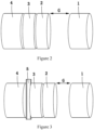
- An exemplary braking system may comprise a static plate 1 that remains stationary; a movable plate 2 that is movably connected to the static plate, for example, the movable plate 2 can move along a guiding element 6; a friction lining 3 on the side of the movable plate 2 facing away from the static plate 1 and a brake component 4.
- the brake component 4 is coupled, for example, to the drive shaft of the elevator traction machine.
- An electromagnetic brake coil 5 is arranged in the static plate 1.
- a spring is also arranged between the static plate 1 and the movable plate 2 to urge the movable plate 2 to be pushed toward the brake component 4, so that the friction lining 3 on the movable plate 2 and the brake component 4 are engaged with each other when the electromagnetic brake coil 5 is not energized, thereby suppressing the rotation of the drive shaft of the traction machine of the elevator.
- This state is also referred to as a brake state.
- the electromagnetic brake coil 5 When the electromagnetic brake coil 5 is energized, a magnetic field 7 is generated, thereby generating an attractive force to the movable plate 2, which overcomes the thrust of the spring to attract the movable plate 2 to be in contact with the static plate 1, thereby releasing the brake component 4 to allow the rotation of the drive shaft of the traction machine.
- the friction lining 3 will be constantly worn, and when the thickness of the friction lining 3 is smaller than a certain threshold, the friction lining 3 needs to be replaced.
- the maintenance personnel regularly measure onsite the air gap a between the static plate 1 and the movable plate 2 in the brake state, for example, using a feeler gauge to measure the gap a. Since the sum of the thicknesses of the air gap a and the friction lining 3 is a fixed value, the thickness of the friction lining 3 can be calculated through the air gap a.
- a self-checking device and method which provide an automatic checking of the wear degree of the friction lining and at least reduce the required frequency of on-site measurement.
- the air gap a can be automatically calculated by measuring the brake coil inductance L in the brake state, thereby realizing the self-checking of the air gap a and the wear degree of the friction lining.
- a self-checking device which comprises: an inductance testing module configured to measure an electromagnetic brake coil inductance L of the braking device; and a processing module electrically connected to the inductance testing module, and storing a mathematical model of an air gap a between the movable plate and the static plate with respect to the brake coil inductance L in the brake state; wherein, the processing module is configured to perform a checking mode in the brake state of the braking device, and in the checking mode, the processing module receives a current inductance L 0 measured by the inductance testing module, calculates a current air gap a 0 based on the mathematical model stored, and determines a wear degree of the friction lining based on the current air gap a 0 calculated.
- the relationship between the air gap a and the brake coil inductance L in the brake state can be preset by the elevator supplier at first, but this relationship is also directly related to the actual on-site condition of the elevator system. Therefore, some data can be obtained by measurement in a testing mode to train the mathematical model, so that it can be more accurate in subsequent use.
- the mathematical model is trained by receiving, in the testing mode of the braking device, at least two sets of data of corresponding air gaps and brake coil inductances (a 1 , L 1 , a 2 , L 2 ).
- R_IRON represents the total magnetic resistance of the magnetic field 7 in the movable plate 2 and the static plate 1. For a specific braking device, the value R_IRON is a fixed value.
- R_air represents the total magnetic resistance of the magnetic field 7 in the air gap a, which is related to the size of the air gap a.
- R _ air a ⁇ 0 ⁇ S
- ⁇ 0 is the magnetoresistance coefficient of the air, which is a fixed value
- S is the cross-sectional area of the magnetic field passing through the air gap, which is a fixed value for a specific braking device.
- formula (6) includes unknown coefficients k 1 and k 2 , and in order to train the model, at least two sets of data of corresponding air gaps and brake coil inductances are required. In some embodiments, as shown in FIGS.
- these data can be obtained during the installation and testing phases of the elevator braking system, for example, by the following method: measuring an air gap a 1 and a brake coil inductance L 1 in the brake state shown in FIG. 2 ; and measuring an air gap a 2 and a brake coil inductance L 2 in another brake state as shown in FIG. 3 which is entered by lifting the movable plate 2 to insert an object 5 of a specific thickness D, such as a feeler gauge, between the movable plate 2 and the brake component 4, and then releasing the movable plate.
- the air gap a 2 at this time can also be calculated by ai-D. As shown in FIG.
- the processor can determine the coefficients k 1 and k 2 in the model.
- objects 5 with different thicknesses can be inserted according to the above method to obtain more sets of data, such as 3 sets, 4 sets, or even 10 sets, etc., and these data are processed using known mathematical methods, thereby making the model more accurate.
- the braking device can be put into daily use. It should be understood that the use procedure and the testing procedure can be performed independently.
- the processor may be configured to execute a checking mode in which the current air gap a 0 may be calculated based on the current measured brake coil inductance L 0 .
- the processing module is configured to repeat the checking mode at specific time intervals, such as every two weeks. In the checking mode, as shown in FIG. 5 , the brake coil inductance L 0 in the brake state is measured, the current air gap a 0 is calculated, and the wear degree of the friction lining is determined based thereupon accordingly.
- the processing module is configured to perform certain operations when the monitored current air gap is greater than a threshold, for example, sending an alarm message to an operator for maintenance, such as replacing the friction lining, or even shutting down the elevator system.
- the aforementioned automatic checking device can replace traditional manual maintenance or at least reduce the frequency of manual maintenance. For example, manual measurements can be performed at longer intervals, such as one month or two months.
- the data of the air gap and the brake coil inductance obtained during the testing mode are the data obtained when the friction lining is not worn, while the data after the actual wear of the friction lining can be obtained during routine maintenance, use of these data for the correction of the mathematical model can make the mathematical model more accurate, especially in the next wear cycle after the friction lining is replaced.
- the model corrected by using the data when the friction lining is worn obtained in the previous cycle can be used to estimate the air gap more accurately.
- the brake coil inductance can be measured in various known ways, for example, a sinusoidal voltage may be input using a PWM circuit (Pulse Width Modulation Circuit) for measurement.
- U is the sinusoidal voltage input through the PWM circuit;
- a PWM circuit already exists, which, for example, is used for modulating the input voltage, so that the control logic of the PWM circuit can be simply adjusted to measure the inductance of the brake coil.
- a PWM circuit can be added to a system that is not configured with such a circuit.
- the PWM circuit may be integrated into the inverter circuit of the elevator traction machine. Therefore, for an elevator system, the addition of the self-checking system according to the embodiments of the present invention will not bring a significant increase in cost, and for the existing elevator systems, the aforementioned functions can be realized only by simple modification.
- the brake coil inductance can be measured by any other suitable means.
- an elevator system comprising the self-checking device according to the various embodiments is further provided.
- a self-checking method for a braking device comprises: establishing a mathematical model of an air gap a between the movable plate and the static plate with respect to a brake coil inductance L in a brake state; executing a checking mode in the brake state of the braking device to measure a current inductance Lo; and calculating a current air gap a 0 based on the mathematical model, and determining a wear degree of the friction lining based on the current air gap a 0 calculated.
- a computer-readable medium with a computer program stored thereon is further provided, wherein the computer program, when executed, performs the method according to the various embodiments.
Landscapes
- Engineering & Computer Science (AREA)
- Physics & Mathematics (AREA)
- General Engineering & Computer Science (AREA)
- Theoretical Computer Science (AREA)
- General Physics & Mathematics (AREA)
- Evolutionary Computation (AREA)
- Mechanical Engineering (AREA)
- Automation & Control Theory (AREA)
- Computer Vision & Pattern Recognition (AREA)
- Geometry (AREA)
- Artificial Intelligence (AREA)
- Computer Hardware Design (AREA)
- Software Systems (AREA)
- Medical Informatics (AREA)
- Cage And Drive Apparatuses For Elevators (AREA)
- Maintenance And Inspection Apparatuses For Elevators (AREA)
- Braking Arrangements (AREA)
- Elevator Control (AREA)
Applications Claiming Priority (1)
| Application Number | Priority Date | Filing Date | Title |
|---|---|---|---|
| CN202210568134.8A CN117142287A (zh) | 2022-05-24 | 2022-05-24 | 用于制动装置的自检测装置和方法及电梯系统 |
Publications (2)
| Publication Number | Publication Date |
|---|---|
| EP4282802A1 true EP4282802A1 (fr) | 2023-11-29 |
| EP4282802B1 EP4282802B1 (fr) | 2025-10-29 |
Family
ID=84361752
Family Applications (1)
| Application Number | Title | Priority Date | Filing Date |
|---|---|---|---|
| EP22209381.7A Active EP4282802B1 (fr) | 2022-05-24 | 2022-11-24 | Dispositif et procédé de vérification automatique pour dispositif de freinage et système d'ascenseur |
Country Status (4)
| Country | Link |
|---|---|
| US (1) | US20230382686A1 (fr) |
| EP (1) | EP4282802B1 (fr) |
| CN (1) | CN117142287A (fr) |
| ES (1) | ES3054736T3 (fr) |
Families Citing this family (1)
| Publication number | Priority date | Publication date | Assignee | Title |
|---|---|---|---|---|
| US20230249942A1 (en) * | 2022-01-26 | 2023-08-10 | Tk Elevator Innovation And Operations Gmbh | Systems and methods for monitoring elevator dual coil electromechanical brakes |
Citations (5)
| Publication number | Priority date | Publication date | Assignee | Title |
|---|---|---|---|---|
| WO2010061049A1 (fr) * | 2008-11-03 | 2010-06-03 | Kone Corporation | Dispositif et procédé pour superviser le fonctionnement d'un frein |
| WO2015193834A1 (fr) * | 2014-06-19 | 2015-12-23 | Kone Corporation | Système, frein de machinerie et procédé de commande du frein de machinerie |
| WO2018202745A1 (fr) * | 2017-05-04 | 2018-11-08 | Thyssenkrupp Elevator Ag | Dispositif de détection pour détecter l'usure d'un patin de frein d'un frein électromagnétique et un ascenseur |
| EP3587325A1 (fr) * | 2018-06-29 | 2020-01-01 | KONE Corporation | Procédé de diagnostic et/ou de maintenance d'un frein d'un système de transport, programme logiciel et appareil de frein |
| EP4056510A1 (fr) * | 2021-03-08 | 2022-09-14 | Otis Elevator Company | Procédé de détection d'usure de frein d'ascenseur, dispositif de détection et frein d'ascenseur |
Family Cites Families (2)
| Publication number | Priority date | Publication date | Assignee | Title |
|---|---|---|---|---|
| CN206943283U (zh) * | 2017-05-04 | 2018-01-30 | 蒂森克虏伯电梯(上海)有限公司 | 用于检测电磁制动器的制动片磨损的检测装置及电梯 |
| EP3556699A1 (fr) * | 2018-04-19 | 2019-10-23 | KONE Corporation | Solution de surveillance pour système de convoyeur |
-
2022
- 2022-05-24 CN CN202210568134.8A patent/CN117142287A/zh active Pending
- 2022-10-13 US US17/965,376 patent/US20230382686A1/en active Pending
- 2022-11-24 EP EP22209381.7A patent/EP4282802B1/fr active Active
- 2022-11-24 ES ES22209381T patent/ES3054736T3/es active Active
Patent Citations (5)
| Publication number | Priority date | Publication date | Assignee | Title |
|---|---|---|---|---|
| WO2010061049A1 (fr) * | 2008-11-03 | 2010-06-03 | Kone Corporation | Dispositif et procédé pour superviser le fonctionnement d'un frein |
| WO2015193834A1 (fr) * | 2014-06-19 | 2015-12-23 | Kone Corporation | Système, frein de machinerie et procédé de commande du frein de machinerie |
| WO2018202745A1 (fr) * | 2017-05-04 | 2018-11-08 | Thyssenkrupp Elevator Ag | Dispositif de détection pour détecter l'usure d'un patin de frein d'un frein électromagnétique et un ascenseur |
| EP3587325A1 (fr) * | 2018-06-29 | 2020-01-01 | KONE Corporation | Procédé de diagnostic et/ou de maintenance d'un frein d'un système de transport, programme logiciel et appareil de frein |
| EP4056510A1 (fr) * | 2021-03-08 | 2022-09-14 | Otis Elevator Company | Procédé de détection d'usure de frein d'ascenseur, dispositif de détection et frein d'ascenseur |
Also Published As
| Publication number | Publication date |
|---|---|
| ES3054736T3 (en) | 2026-02-05 |
| EP4282802B1 (fr) | 2025-10-29 |
| US20230382686A1 (en) | 2023-11-30 |
| CN117142287A (zh) | 2023-12-01 |
Similar Documents
| Publication | Publication Date | Title |
|---|---|---|
| EP3748351B1 (fr) | Dispositif d'inspection de câble métallique, système d'inspection de câble métallique et procédé d'inspection de câble métallique | |
| EP4282802A1 (fr) | Dispositif et procédé de vérification automatique pour dispositif de freinage et système d'ascenseur | |
| US9335380B2 (en) | Device for detecting insulation degradation | |
| CN101109729B (zh) | 钢丝绳的探伤装置 | |
| KR101798689B1 (ko) | 계기용 변류기를 포함하는 전원 장치 및 계기용 변류기의 보상 방법 | |
| CN105005293B (zh) | 用于实时测试控制器的计算机执行的方法和模拟器 | |
| US20130074606A1 (en) | Device and method for indicating if a fastening element has reached a tensile yield limit load | |
| CN104573315B (zh) | 一种基于状态检修的输变电设备故障率的计算方法 | |
| US20180011136A1 (en) | Fault point locating device and method, electric power system monitoring system, and facility planning support system | |
| CN108700627B (zh) | 用于测量电力变压器中的功率损耗的方法和系统 | |
| CN115303905B (zh) | 曳引机监测装置及方法 | |
| EP4056510B1 (fr) | Procédé de détection d'usure de frein d'ascenseur, dispositif de détection et frein d'ascenseur | |
| CN102323168B (zh) | 一种齿轮弯曲疲劳试验锤头加载偏差值的测试方法 | |
| US20200209080A1 (en) | System and method for measuring electromagnetic characteristic on a component | |
| US20190362860A1 (en) | Systems and methods of monitoring operation of control rod mechanisms of nuclear power plants | |
| US20220291303A1 (en) | Process for estimating the residual life of the electromagnet of a vibrating feeder of articles | |
| EP1430297B1 (fr) | Procede et dispositif de controle d'empilements de toles de fer feuilletees de machines electriques a la recherche de courts-circuits entre toles | |
| JP2017198601A (ja) | トップ反の目とび検出装置と検出方法およびトップ反の検査装置 | |
| KR20200122005A (ko) | 무게측정이 가능한 크레인 장치 | |
| JPS63115046A (ja) | 溶接部の損傷検出方法 | |
| CN110346232A (zh) | 一种损坏检测装置及检测方法 | |
| EP4585548A1 (fr) | Procédé de détection d'état de frein, système correspondant, frein d'ascenseur et système d'ascenseur | |
| WO2014129125A1 (fr) | Dispositif, procédé et programme d'assistance à la conception pour la fiabilité | |
| JP2841578B2 (ja) | 鉄損値測定データの校正方法及び校正装置 | |
| WO2021237579A1 (fr) | Procédé de diagnostic de défaut d'adhérence de matière étrangère de stator de moteur linéaire à base d'analyse statistique |
Legal Events
| Date | Code | Title | Description |
|---|---|---|---|
| PUAI | Public reference made under article 153(3) epc to a published international application that has entered the european phase |
Free format text: ORIGINAL CODE: 0009012 |
|
| STAA | Information on the status of an ep patent application or granted ep patent |
Free format text: STATUS: THE APPLICATION HAS BEEN PUBLISHED |
|
| AK | Designated contracting states |
Kind code of ref document: A1 Designated state(s): AL AT BE BG CH CY CZ DE DK EE ES FI FR GB GR HR HU IE IS IT LI LT LU LV MC ME MK MT NL NO PL PT RO RS SE SI SK SM TR |
|
| STAA | Information on the status of an ep patent application or granted ep patent |
Free format text: STATUS: REQUEST FOR EXAMINATION WAS MADE |
|
| 17P | Request for examination filed |
Effective date: 20240522 |
|
| RBV | Designated contracting states (corrected) |
Designated state(s): AL AT BE BG CH CY CZ DE DK EE ES FI FR GB GR HR HU IE IS IT LI LT LU LV MC ME MK MT NL NO PL PT RO RS SE SI SK SM TR |
|
| GRAP | Despatch of communication of intention to grant a patent |
Free format text: ORIGINAL CODE: EPIDOSNIGR1 |
|
| STAA | Information on the status of an ep patent application or granted ep patent |
Free format text: STATUS: GRANT OF PATENT IS INTENDED |
|
| GRAJ | Information related to disapproval of communication of intention to grant by the applicant or resumption of examination proceedings by the epo deleted |
Free format text: ORIGINAL CODE: EPIDOSDIGR1 |
|
| STAA | Information on the status of an ep patent application or granted ep patent |
Free format text: STATUS: REQUEST FOR EXAMINATION WAS MADE |
|
| INTG | Intention to grant announced |
Effective date: 20250422 |
|
| GRAP | Despatch of communication of intention to grant a patent |
Free format text: ORIGINAL CODE: EPIDOSNIGR1 |
|
| STAA | Information on the status of an ep patent application or granted ep patent |
Free format text: STATUS: GRANT OF PATENT IS INTENDED |
|
| INTC | Intention to grant announced (deleted) | ||
| INTG | Intention to grant announced |
Effective date: 20250528 |
|
| RIN1 | Information on inventor provided before grant (corrected) |
Inventor name: LI, GUOSONG |
|
| GRAS | Grant fee paid |
Free format text: ORIGINAL CODE: EPIDOSNIGR3 |
|
| GRAA | (expected) grant |
Free format text: ORIGINAL CODE: 0009210 |
|
| STAA | Information on the status of an ep patent application or granted ep patent |
Free format text: STATUS: THE PATENT HAS BEEN GRANTED |
|
| AK | Designated contracting states |
Kind code of ref document: B1 Designated state(s): AL AT BE BG CH CY CZ DE DK EE ES FI FR GB GR HR HU IE IS IT LI LT LU LV MC ME MK MT NL NO PL PT RO RS SE SI SK SM TR |
|
| REG | Reference to a national code |
Ref country code: CH Ref legal event code: F10 Free format text: ST27 STATUS EVENT CODE: U-0-0-F10-F00 (AS PROVIDED BY THE NATIONAL OFFICE) Effective date: 20251029 Ref country code: GB Ref legal event code: FG4D |
|
| REG | Reference to a national code |
Ref country code: IE Ref legal event code: FG4D |
|
| REG | Reference to a national code |
Ref country code: DE Ref legal event code: R096 Ref document number: 602022023866 Country of ref document: DE |
|
| PGFP | Annual fee paid to national office [announced via postgrant information from national office to epo] |
Ref country code: DE Payment date: 20251126 Year of fee payment: 4 |
|
| PGFP | Annual fee paid to national office [announced via postgrant information from national office to epo] |
Ref country code: AT Payment date: 20260113 Year of fee payment: 4 |
|
| PGFP | Annual fee paid to national office [announced via postgrant information from national office to epo] |
Ref country code: FR Payment date: 20251119 Year of fee payment: 4 |
|
| PGFP | Annual fee paid to national office [announced via postgrant information from national office to epo] |
Ref country code: ES Payment date: 20251204 Year of fee payment: 4 |
|
| REG | Reference to a national code |
Ref country code: ES Ref legal event code: FG2A Ref document number: 3054736 Country of ref document: ES Kind code of ref document: T3 Effective date: 20260205 |
|
| REG | Reference to a national code |
Ref country code: NL Ref legal event code: MP Effective date: 20251029 |
|
| REG | Reference to a national code |
Ref country code: LT Ref legal event code: MG9D |
|
| PG25 | Lapsed in a contracting state [announced via postgrant information from national office to epo] |
Ref country code: NO Free format text: LAPSE BECAUSE OF FAILURE TO SUBMIT A TRANSLATION OF THE DESCRIPTION OR TO PAY THE FEE WITHIN THE PRESCRIBED TIME-LIMIT Effective date: 20260129 |
|
| PG25 | Lapsed in a contracting state [announced via postgrant information from national office to epo] |
Ref country code: HR Free format text: LAPSE BECAUSE OF FAILURE TO SUBMIT A TRANSLATION OF THE DESCRIPTION OR TO PAY THE FEE WITHIN THE PRESCRIBED TIME-LIMIT Effective date: 20251029 Ref country code: AT Free format text: LAPSE BECAUSE OF FAILURE TO SUBMIT A TRANSLATION OF THE DESCRIPTION OR TO PAY THE FEE WITHIN THE PRESCRIBED TIME-LIMIT Effective date: 20251029 Ref country code: FI Free format text: LAPSE BECAUSE OF FAILURE TO SUBMIT A TRANSLATION OF THE DESCRIPTION OR TO PAY THE FEE WITHIN THE PRESCRIBED TIME-LIMIT Effective date: 20251029 |
|
| REG | Reference to a national code |
Ref country code: AT Ref legal event code: MK05 Ref document number: 1851389 Country of ref document: AT Kind code of ref document: T Effective date: 20251029 |
|
| PG25 | Lapsed in a contracting state [announced via postgrant information from national office to epo] |
Ref country code: NL Free format text: LAPSE BECAUSE OF FAILURE TO SUBMIT A TRANSLATION OF THE DESCRIPTION OR TO PAY THE FEE WITHIN THE PRESCRIBED TIME-LIMIT Effective date: 20251029 |
|
| PG25 | Lapsed in a contracting state [announced via postgrant information from national office to epo] |
Ref country code: RS Free format text: LAPSE BECAUSE OF FAILURE TO SUBMIT A TRANSLATION OF THE DESCRIPTION OR TO PAY THE FEE WITHIN THE PRESCRIBED TIME-LIMIT Effective date: 20260129 |
|
| PG25 | Lapsed in a contracting state [announced via postgrant information from national office to epo] |
Ref country code: IS Free format text: LAPSE BECAUSE OF FAILURE TO SUBMIT A TRANSLATION OF THE DESCRIPTION OR TO PAY THE FEE WITHIN THE PRESCRIBED TIME-LIMIT Effective date: 20260228 |
|
| PG25 | Lapsed in a contracting state [announced via postgrant information from national office to epo] |
Ref country code: PT Free format text: LAPSE BECAUSE OF FAILURE TO SUBMIT A TRANSLATION OF THE DESCRIPTION OR TO PAY THE FEE WITHIN THE PRESCRIBED TIME-LIMIT Effective date: 20260302 |
|
| PG25 | Lapsed in a contracting state [announced via postgrant information from national office to epo] |
Ref country code: PL Free format text: LAPSE BECAUSE OF FAILURE TO SUBMIT A TRANSLATION OF THE DESCRIPTION OR TO PAY THE FEE WITHIN THE PRESCRIBED TIME-LIMIT Effective date: 20251029 |
|
| PG25 | Lapsed in a contracting state [announced via postgrant information from national office to epo] |
Ref country code: LV Free format text: LAPSE BECAUSE OF FAILURE TO SUBMIT A TRANSLATION OF THE DESCRIPTION OR TO PAY THE FEE WITHIN THE PRESCRIBED TIME-LIMIT Effective date: 20251029 |