EP4282832A1 - Procédé et système de production de boue granulaire - Google Patents
Procédé et système de production de boue granulaire Download PDFInfo
- Publication number
- EP4282832A1 EP4282832A1 EP22175539.0A EP22175539A EP4282832A1 EP 4282832 A1 EP4282832 A1 EP 4282832A1 EP 22175539 A EP22175539 A EP 22175539A EP 4282832 A1 EP4282832 A1 EP 4282832A1
- Authority
- EP
- European Patent Office
- Prior art keywords
- biomass
- clarification tank
- wastewater
- bsus
- suspended
- Prior art date
- Legal status (The legal status is an assumption and is not a legal conclusion. Google has not performed a legal analysis and makes no representation as to the accuracy of the status listed.)
- Pending
Links
- 239000010802 sludge Substances 0.000 title claims abstract description 110
- 238000000034 method Methods 0.000 title claims description 85
- 239000002028 Biomass Substances 0.000 claims abstract description 158
- 238000005352 clarification Methods 0.000 claims abstract description 102
- 239000002351 wastewater Substances 0.000 claims abstract description 99
- XLYOFNOQVPJJNP-UHFFFAOYSA-N water Substances O XLYOFNOQVPJJNP-UHFFFAOYSA-N 0.000 claims abstract description 25
- 238000010008 shearing Methods 0.000 claims abstract description 19
- 238000002156 mixing Methods 0.000 claims abstract description 16
- 238000004519 manufacturing process Methods 0.000 claims abstract description 7
- 238000005273 aeration Methods 0.000 claims abstract description 4
- 230000008569 process Effects 0.000 claims description 70
- 238000009423 ventilation Methods 0.000 claims description 41
- 238000000926 separation method Methods 0.000 claims description 29
- 238000004140 cleaning Methods 0.000 claims description 18
- 239000000758 substrate Substances 0.000 claims description 7
- 238000003756 stirring Methods 0.000 claims description 3
- 238000004065 wastewater treatment Methods 0.000 claims description 3
- 239000012071 phase Substances 0.000 description 19
- 244000005700 microbiome Species 0.000 description 18
- 239000000725 suspension Substances 0.000 description 14
- 238000006243 chemical reaction Methods 0.000 description 11
- 238000005469 granulation Methods 0.000 description 8
- 230000003179 granulation Effects 0.000 description 8
- 239000007790 solid phase Substances 0.000 description 8
- 239000007791 liquid phase Substances 0.000 description 7
- 239000010865 sewage Substances 0.000 description 7
- QVGXLLKOCUKJST-UHFFFAOYSA-N atomic oxygen Chemical compound [O] QVGXLLKOCUKJST-UHFFFAOYSA-N 0.000 description 6
- 239000008187 granular material Substances 0.000 description 6
- 229910052760 oxygen Inorganic materials 0.000 description 6
- 239000001301 oxygen Substances 0.000 description 6
- 230000015556 catabolic process Effects 0.000 description 5
- 239000003344 environmental pollutant Substances 0.000 description 4
- 231100000719 pollutant Toxicity 0.000 description 4
- 239000007787 solid Substances 0.000 description 4
- 239000000126 substance Substances 0.000 description 4
- 238000010276 construction Methods 0.000 description 3
- 230000000694 effects Effects 0.000 description 3
- 239000000463 material Substances 0.000 description 3
- 239000004753 textile Substances 0.000 description 3
- OKTJSMMVPCPJKN-UHFFFAOYSA-N Carbon Chemical compound [C] OKTJSMMVPCPJKN-UHFFFAOYSA-N 0.000 description 2
- 230000008901 benefit Effects 0.000 description 2
- 229910052799 carbon Inorganic materials 0.000 description 2
- 238000006731 degradation reaction Methods 0.000 description 2
- 238000011161 development Methods 0.000 description 2
- 230000018109 developmental process Effects 0.000 description 2
- 210000004602 germ cell Anatomy 0.000 description 2
- 230000010354 integration Effects 0.000 description 2
- 239000000203 mixture Substances 0.000 description 2
- 230000001546 nitrifying effect Effects 0.000 description 2
- 239000005014 poly(hydroxyalkanoate) Substances 0.000 description 2
- 229920000903 polyhydroxyalkanoate Polymers 0.000 description 2
- 229920000642 polymer Polymers 0.000 description 2
- 238000004062 sedimentation Methods 0.000 description 2
- 238000012163 sequencing technique Methods 0.000 description 2
- 241000894007 species Species 0.000 description 2
- QGZKDVFQNNGYKY-UHFFFAOYSA-O Ammonium Chemical compound [NH4+] QGZKDVFQNNGYKY-UHFFFAOYSA-O 0.000 description 1
- 238000005276 aerator Methods 0.000 description 1
- 230000015572 biosynthetic process Effects 0.000 description 1
- 238000010908 decantation Methods 0.000 description 1
- 230000008021 deposition Effects 0.000 description 1
- 238000009792 diffusion process Methods 0.000 description 1
- 230000007613 environmental effect Effects 0.000 description 1
- 238000005429 filling process Methods 0.000 description 1
- 230000005484 gravity Effects 0.000 description 1
- 239000004615 ingredient Substances 0.000 description 1
- 230000003993 interaction Effects 0.000 description 1
- 239000007788 liquid Substances 0.000 description 1
- 238000001000 micrograph Methods 0.000 description 1
- 235000015097 nutrients Nutrition 0.000 description 1
- 239000002245 particle Substances 0.000 description 1
- 230000035515 penetration Effects 0.000 description 1
- 229920003023 plastic Polymers 0.000 description 1
- 239000004033 plastic Substances 0.000 description 1
- 230000009467 reduction Effects 0.000 description 1
- 238000004904 shortening Methods 0.000 description 1
- 238000003860 storage Methods 0.000 description 1
Images


Classifications
-
- C—CHEMISTRY; METALLURGY
- C02—TREATMENT OF WATER, WASTE WATER, SEWAGE, OR SLUDGE
- C02F—TREATMENT OF WATER, WASTE WATER, SEWAGE, OR SLUDGE
- C02F3/00—Biological treatment of water, waste water, or sewage
- C02F3/02—Aerobic processes
- C02F3/12—Activated sludge processes
- C02F3/1278—Provisions for mixing or aeration of the mixed liquor
- C02F3/1284—Mixing devices
-
- C—CHEMISTRY; METALLURGY
- C02—TREATMENT OF WATER, WASTE WATER, SEWAGE, OR SLUDGE
- C02F—TREATMENT OF WATER, WASTE WATER, SEWAGE, OR SLUDGE
- C02F3/00—Biological treatment of water, waste water, or sewage
- C02F3/006—Regulation methods for biological treatment
-
- C—CHEMISTRY; METALLURGY
- C02—TREATMENT OF WATER, WASTE WATER, SEWAGE, OR SLUDGE
- C02F—TREATMENT OF WATER, WASTE WATER, SEWAGE, OR SLUDGE
- C02F3/00—Biological treatment of water, waste water, or sewage
- C02F3/02—Aerobic processes
- C02F3/08—Aerobic processes using moving contact bodies
- C02F3/085—Fluidized beds
-
- C—CHEMISTRY; METALLURGY
- C02—TREATMENT OF WATER, WASTE WATER, SEWAGE, OR SLUDGE
- C02F—TREATMENT OF WATER, WASTE WATER, SEWAGE, OR SLUDGE
- C02F3/00—Biological treatment of water, waste water, or sewage
- C02F3/02—Aerobic processes
- C02F3/10—Packings; Fillings; Grids
- C02F3/103—Textile-type packing
-
- C—CHEMISTRY; METALLURGY
- C02—TREATMENT OF WATER, WASTE WATER, SEWAGE, OR SLUDGE
- C02F—TREATMENT OF WATER, WASTE WATER, SEWAGE, OR SLUDGE
- C02F2209/00—Controlling or monitoring parameters in water treatment
- C02F2209/38—Gas flow rate
-
- C—CHEMISTRY; METALLURGY
- C02—TREATMENT OF WATER, WASTE WATER, SEWAGE, OR SLUDGE
- C02F—TREATMENT OF WATER, WASTE WATER, SEWAGE, OR SLUDGE
- C02F2301/00—General aspects of water treatment
- C02F2301/02—Fluid flow conditions
- C02F2301/026—Spiral, helicoidal, radial
-
- C—CHEMISTRY; METALLURGY
- C02—TREATMENT OF WATER, WASTE WATER, SEWAGE, OR SLUDGE
- C02F—TREATMENT OF WATER, WASTE WATER, SEWAGE, OR SLUDGE
- C02F3/00—Biological treatment of water, waste water, or sewage
- C02F3/02—Aerobic processes
- C02F3/10—Packings; Fillings; Grids
- C02F3/104—Granular carriers
-
- C—CHEMISTRY; METALLURGY
- C02—TREATMENT OF WATER, WASTE WATER, SEWAGE, OR SLUDGE
- C02F—TREATMENT OF WATER, WASTE WATER, SEWAGE, OR SLUDGE
- C02F3/00—Biological treatment of water, waste water, or sewage
- C02F3/02—Aerobic processes
- C02F3/12—Activated sludge processes
- C02F3/1236—Particular type of activated sludge installations
- C02F3/1263—Sequencing batch reactors [SBR]
-
- C—CHEMISTRY; METALLURGY
- C02—TREATMENT OF WATER, WASTE WATER, SEWAGE, OR SLUDGE
- C02F—TREATMENT OF WATER, WASTE WATER, SEWAGE, OR SLUDGE
- C02F3/00—Biological treatment of water, waste water, or sewage
- C02F3/02—Aerobic processes
- C02F3/12—Activated sludge processes
- C02F3/20—Activated sludge processes using diffusers
- C02F3/201—Perforated, resilient plastic diffusers, e.g. membranes, sheets, foils, tubes, hoses
Definitions
- the invention relates to a method for producing granular sludge, in particular as part of an SBR process, and to a system for producing granular sludge.
- the purified clear water is removed from the sewage treatment plant or the clarification tank in the subsequent withdrawal phase, while part of the settled biomass is usually withdrawn from the system (per cycle/per day) as excess sludge and is therefore not used further in the treatment process.
- the cleaning cycle then begins again.
- the microorganisms that are enriched in the system and the ability of the sludge flakes to settle in the suspension or suspended biomass are crucial for the efficiency of this SBR process.
- the mud flakes in the suspension can be separated from the water phase by solid-liquid separation in the form of sedimentation.
- the sedimentation process is the decisive factor for treatment. Namely, it limits the amount of biomass in the system, the possible exchange ratio and the required processing time. The more clearly the sludge flakes settle in the suspension, the easier it is to separate the solid phase in the form of activated sludge flakes in the suspension and the liquid phase, the treated wastewater or the clear water.
- the disadvantage here is that the settling rate of the suspended biomass is low due to the structure and the resulting density of the sludge flakes, which is only slightly higher than that of water (flakes: 1.038 g/ml flakes; water: 0.997 g/ml). Therefore, in the SBR process, long settling phases are required for the process in order to achieve a clear separation between the solid and liquid phase. This significantly extends the treatment process and in order to increase the treatment capacity, correspondingly larger sewage treatment plants must be provided to treat the wastewater.
- FBBR Fixed Bed Biofilm Reactor
- additional solid support bodies in the clarification tank for example textile fixed beds, past which the wastewater to be cleaned is passed.
- the carrier bodies have a large surface area on which microorganisms from the supplied wastewater or activated sludge settle, so that sessile biomass is formed.
- the suspended biomass and the sessile biomass in the clarification tank feed on pollutants and nutrients in the wastewater and convert them, for example when breaking down ammonium through nitrification.
- the conversion processes of carbon degradation and nitrification require oxygen, which is introduced into the wastewater to be cleaned in the form of air bubbles via ventilation systems within the clarification tank.
- a sewage treatment plant with a fluidized bed can also be provided, in which movable support bodies are inserted into the process on which sessile biomass can settle.
- the sessile biomass Due to the adhesion and growth of biomass on the fixed or movable support bodies, the sessile biomass can remain in the system longer than the suspended biomass. This gives slow-growing microorganisms better growth conditions than in suspension. Nitrifying species usually grow more slowly than microorganisms that break down carbon. Therefore this will be Growth of nitrifying species in the sessile biomass is favored. As a result, a sessile nitrification rate, ie the breakdown of pollutants by the sessile microorganisms, can be increased up to a certain layer thickness of the sessile biomass.
- the object of the present invention is to provide a method and a system which easily enable an optimized and significantly faster treatment of wastewater as part of an SBR process.
- the invention further relates to a system for producing granular sludge, in particular for carrying out the method according to the invention.
- the granular sludge can have biomass in the form of granules or in a form similar to granules, whereby the shape of this biomass can deviate from the ideal spherical shape due to the circumstances during the granulation process. Accordingly, granular or granule-like sludge is produced in the process according to the invention.
- the biofilm sheared off from the carrier bodies has a very fast settling time, this settling time being similar to that of granules. This results in a significantly faster and clear separation of the liquid and solid phases in the SBR process. But the degradation properties in the biological treatment process are also improved, comparable to granular sludge, especially aerobic granular sludge (AGS), which in turn increases the performance of the process.
- AGS aerobic granular sludge
- the granular sludge is not produced, as in conventional granulation processes, from the suspended biomass, which settles very slowly or has poor settling properties, but explicitly from the rapidly settling heavy sludge fraction, in which the biofilm (sessile biomass) which has been sheared off from at least one carrier body ) is located.
- This granulate production or this granulation process from the sheared biofilm is preferably carried out by bringing the wastewater into contact with the sheared biofilm held in the clarification tank in such a way that the biomass is exposed to a high concentration, which leads to better diffusion of the substrate into the different zones of the sheared biofilm, which can be converted under anoxic conditions, whereby the sheared biofilm converts into granular sludge with the participation of other processes.
- the property of sessile biomass or the sheared biofilm is specifically exploited in that slow-growing microorganisms on the surface of the sheared biofilm can only absorb the substrate in the wastewater slowly and thus promote penetration into the sheared biofilm and thereby the rapid conversion into just enable granular mud.
- the shearing of the sessile biomass takes place simultaneously with the ventilation of the sessile and the Suspended biomass takes place in that the air bubbles let into the wastewater by a ventilation system with an intensity shear off the sessile biomass from the respective carrier body, in particular the carrier body of the fixed bed module, in particular by setting a changing intensity of the air bubbles.
- the air bubbles can also be used to shear off the sessile biomass in parallel to the aeration of the biomass, so that in principle no additional device is necessary, which simplifies the process overall and makes it easier to control. Intermittent ventilation in particular can lead to very efficient shearing.
- the sessile biomass can be sheared off instead or in addition by the moving carrier bodies colliding or touching each other in the wastewater, possibly supported by a movement induced by the air bubbles in the carrier bodies, and the sessile biomass thereby also mechanically is sheared off.
- the mixing and/or whirling of suspended biomass that settles on a bottom of the clarification tank is carried out by filling the wastewater on the underside, i.e. in the area of the bottom of the clarification tank, via the at least one inlet pipes into the clarification tank becomes. Accordingly, no additional device for mixing or whirling is necessary.
- the wastewater could also be poured into the clarification tank from the top and the settled suspended biomass could be mixed or whirled up using an agitator.
- contaminated wastewater can be brought into contact with the previously settled suspended biomass, in particular the sheared biofilm in the heavy sludge fraction, in order to subsequently enable the sheared biofilm to be converted into granular sludge.
- the clarification tank is filled with contaminated wastewater via at least one, preferably two inlet pipes in such a way that a spiral flow is generated in order to remove the suspended biomass that settles in a lower area and/or at the bottom of the clarification tank. to mix and/or stir up.
- the wastewater can interact efficiently with the sheared biofilm or the heavy sludge fraction by efficiently whirling up or loosening the wastewater itself by the spirally introduced wastewater. With only one inlet line, the spiral whirling can take place in interaction with the container or the container walls.
- the wastewater can better supply the sheared biofilm, which then results in a faster conversion into granular sludge, and subsequently a more effective biological treatment process or cleaning process through the sheared biofilm or the resulting granular sludge, which makes the treatment process very efficient and quick.
- the device for shearing the sessile biomass from the at least one carrier body is formed by the ventilation system, which can generate air bubbles with such an intensity and let them into the wastewater that the sessile biomass detaches from the at least one carrier body and
- the resulting sheared biomass can pass into the wastewater as suspended biomass.
- the separation system is formed from a pipe structure which is composed of several extended perforated pipes, the pipes and/or the pipe structure being fastened in the upper region of the clarification tank, preferably above on a frame of the fixed bed module.
- the pipe structure or the perforated pipes advantageously covers or surrounds a larger area, so that the suspended sludge flakes with poor settling properties (light sludge fraction) are removed over a large area from the upper area of the clarification tank can be subtracted, which makes the separation of the phases faster.
- the means for mixing and / or whirling up the suspended biomass, which settles on a bottom of the clarification tank, is or are formed by the at least one inlet line itself, for example by arranging the at least one inlet line on the underside Clarification tank can ensure that the suspended biomass deposited on the ground is automatically mixed or whirled up by the waste water introduced.
- At least one, preferably two inlet pipes are provided in the lower region of the clarifier, which are arranged in the container or relative to one another in such a way that the wastewater flows through the at least one, preferably at least two inlet pipes in a spiral flow into the clarifier can be let in to mix and/or stir up the suspended biomass that settles at the bottom of the clarifier. This enables effective contact between the wastewater to be cleaned and the heavy sludge fraction.
- a system 100 for producing granular sludge Fgran is shown with a clarification tank 1, wherein in the clarification tank 1 there is a fixed bed module 2 with an integrated (sludge fraction) separation system 3, which is located in an upper area 1b of the clarification tank 1 above the fixed bed module 2, is arranged.
- the fixed bed module 2 has, as a support body 2a, for example several cords fastened to a frame in the form of synthetic, wastewater-resistant textiles.
- the fixed bed module 2 is also placed above a ventilation system 4 consisting of a main air line 4a and several ventilation elements 4b, for example pipe aerators with holes 4c or perforations.
- a fluidized bed 6 (in Fig. 1 not shown), the support body 6a of which can move freely in the wastewater A filled into the clarification tank 1.
- an inlet line 5 is arranged below the ventilation elements 4b.
- wastewater A activated sludge
- SBR Sequencing Batch Reactor
- sessile biomass Bsess from the microorganisms present in the wastewater A settle on the solid support bodies 2a of the fixed bed module 2 (or alternatively on the movable support bodies 6a of the fluidized bed 6).
- the wastewater A is therefore in the clarification tank 1 on the carrier bodies 2a; 6a passed or are the carrier bodies 2a; 6a is completely immersed in the clarification tank 1 with the filled wastewater A, with sessile microorganisms already settled in the sessile biomass Bsess feeding on the pollutants in the contaminated wastewater A and thereby multiplying.
- the sessile biomass Bsess continues to grow, and depending on the depth in the biofilm there are also sessile microorganisms with different levels of activity, which can also break down different harmful substances in the wastewater A depending on the depth.
- the sessile microorganisms ensure a specific cleaning effect in the wastewater A, for example through so-called nitrification with a specific sessile nitrification rate and/or through the breakdown of organic substances.
- the sessile microorganisms in the sessile biomass Bsess are supplied with oxygen via the ventilation system 4 via the holes 4c in the ventilation elements 4b, since the treatment or cleaning process has a high oxygen requirement.
- Air bubbles L of a certain intensity can therefore be admitted into the wastewater A through the holes 4c, with these air bubbles L also being attached to the support bodies 2a due to the positioning of the ventilation system 4; 6a are passed so that the sessile microorganisms can also be supplied with oxygen for the treatment or cleaning process. This allows the growth of the sessile biomass Bsess on the respective carrier body 2a; 6a are favored.
- the clarification tank 1 As a further biologically active component of the system 100, there are suspended microorganisms in the clarification tank 1, which are in the suspension, ie the sludge-like wastewater A, even away from the carrier body 2a; 6a swim or float, for example as suspended biomass Bsus in the form of suspended mud flakes Fsus. These suspended microorganisms are also carried by the air bubbles L of the ventilation system 4 Oxygen is supplied in order to be able to contribute to the treatment or cleaning process. The suspended microorganisms also contribute to the breakdown of pollutants in the wastewater A, so that the treatment or cleaning process is influenced by both the suspended biomass Bsus and the sessile biomass Bsess.
- the treatment or cleaning process of the wastewater A can be optimized by additionally producing granular sludge Fgran as follows:
- the aim of the direct arrangement of the ventilation system 4 under the fixed bed module 2 or the fluidized bed 6 is that the air bubbles L directly onto the sessile biomass Bsess on the respective carrier body 2a; 6a and can therefore detach or shear off depending on intensity I.
- a higher level of stress in the form of shear stress can be specifically generated on the sessile biomass Bsess due to constantly changing conditions.
- the sessile biomass Bsess can be efficiently removed from the respective carrier body 2a; 6a will be replaced.
- a device with the same effect for shearing off the sessile biomass Bsess for example a mechanical device (not shown), could also be provided.
- mechanical shearing or detachment can also occur due to collisions or contact between the moving carrier bodies 6a.
- the detached sessile biomass Bsess passes into the wastewater A or into the suspension in the form of a sheared biofilm Fshear and also ensures treatment or cleaning of the wastewater A in this.
- the sheared biofilm Fshear has thereby a comparatively high density compared to the suspended sludge flakes Fsus present in the suspension from the outset, so that the sheared biofilm Fshear can settle at a high settling rate in the direction of the bottom 1c of the clarification tank 1.
- the light sludge fraction SI is regularly separated using the separation system 3 removed or withdrawn from the clarifier 1.
- the heavy sludge fraction Sh then remains in the clarification tank 1, which quickly settles on the bottom 1c of the clarification tank 1 and is thereby separated from the clear water K.
- the separation system 3 is made up of a pipe construction 3a with pipes 3b, which runs on the top side of the frame 2b of the fixed bed module 2, and is preferably attached to it.
- the separation system 3 is preferably located in a central region of the clarifier 1, ie essentially below of the fluidized bed 6.
- the pipes 3b of the pipe structure 3a have a perforation 3c through which wastewater A with sludge particles can be drained into the pipes 3b and into at least one drain line 3d.
- the wastewater A discharged in this way can be removed from the process in a targeted or controlled manner, for example via a valve 3e and gravity via the drain line 3d.
- the pipe construction 3a covers or surrounds a large area or level above the fixed bed module 2 or alternatively below the fluidized bed 6, a large part of the light sludge fraction SI, which due to the poor settling properties, continues to be in the upper area 1b of the clarification tank 1 floats, can be efficiently removed or removed via the perforated pipes 3b by opening the valve 3e.
- the solid phase in the suspension is then essentially only formed from the quickly settling, sheared biofilm Fshear, so that the separation system 3 promotes rapid separation of the solid phase (Fshear) and the liquid phase (clear water K). This results in an already efficient enrichment of the heavy sludge fraction Sh on the bottom 1c or in the lower area 1a of the clarification tank 1.
- the further development of the sheared biofilm Fshear in the heavy sludge fraction Sh plays a crucial role in the production of the granular sludge Fgran, which is achieved by specifically bringing the sheared biofilm Fshear into contact with the wastewater A filled in. This is optimized by the fact that the contaminated wastewater A below the ventilation system 4 via the inlet line 5 directly into the already on the ground 1c settled heavy sludge fraction Sh or the sheared off biofilm Fshear is fed.
- the slowly growing microorganisms cultivate by converting the easily degradable COD (chemical oxygen demand) into storage polymers such as polyhydroxyalkanoates (PHA) and/or by providing cores or germ cells (nuclei) in the sheared biofilm Fshear. These form in the sessile biomass Bsess during the growth process on the at least one carrier body 2a, 6a and are therefore also sheared off. Biomass, especially the slowly growing microorganisms, can be cultivated or settled on these nuclei or germ cells.
- COD chemical oxygen demand
- PHA polyhydroxyalkanoates
- the granulation process according to the invention takes advantage of the fact that the sessile biomass Bsess has special properties due to its longer stay on the at least one carrier body 2a, 6a, which can ensure a complete supply of substrate from the wastewater A.
- the sheared biofilm Fshear is converted into granular sludge Fgran, ie granules or granule-like biomass, in a very short time.
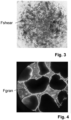
- An example is this granular mud Fgran in Fig. 4 shown, this being as described from the sheared biomass Fshear, as exemplified in Fig. 3 is shown has been converted.
- This produced granular sludge Fgran is subsequently kept in the treatment or cleaning process as a component of the (rapidly settling) suspended biomass Bsus or the heavy sludge fraction Sh and is used specifically for the biological treatment of the contaminated wastewater A.
- granular sludge Fgran can be produced from the sheared-off biofilm Fshear as described by at least halving the conversion time from conventional granulation processes that take place under the same environmental conditions (temperature, load, etc.).
- one or more feed lines 5 in the lower area 1a of the clarification tank 1 can be done in this way be arranged so that a spiral flow of the contaminated wastewater A results in the lower area 1a of the clarification tank 1.
- the settled, sheared biofilm Fshear at the bottom 1c of the clarification tank is effectively whirled up and the wastewater A can interact with it on a large scale in order to then achieve an efficient or rapid conversion into granular sludge Fgran.
- an agitator 7 in Fig. 1 not shown
- a supplementary ventilation system (not shown), which preferably implements a coarse-bubble or intermittent ventilation, is/are provided as a means for mixing and/or whirling up the suspended biomass Bsus together with the sheared-off biofilm Fshear, which is/are intended for whirling up the settled, sheared biofilm Fshear can ensure.
- At least one carrier body 2a, 6a (e.g. a fixed bed module 2 or a fluidized bed 6) is specifically used in an SBR reactor in order to provide a quickly settling, sheared biofilm Fshear in the suspension and this, after it has settled on the bottom 1c of the clarification tank 1, it is converted into granular sludge Fgran in the shortest possible time by conversion processes that take place under the special supply of the wastewater A or by bringing it into contact with the wastewater A. This can then be used for a very efficient treatment of wastewater A, so that in actual fact The overall treatment process allows faster cleaning cycles to be achieved.
- a carrier body 2a, 6a e.g. a fixed bed module 2 or a fluidized bed 6
- the production of granular sludge Fgran as part of an SBR process is then carried out cyclically and is divided into several Fig. 2 Phases shown as examples, filling (ST1), aeration (ST2), settling (ST3) and subsequent decantation (ST4).
- ST1 filling
- ST2 aeration
- ST3 settling
- ST4 subsequent decantation
- the production of the granular sludge Fgran takes place parallel to the treatment or cleaning process: At the beginning (ST0) of a (cleaning) cycle or at the end of the previous cycle, the SBR zone in which the wastewater A is treated according to the SBR process within the clarification tank 1 is partially (approx.
- the cycle starts in a first step ST1 with the filling of the clarification tank 1 with (raw) wastewater A via the at least one below (see. Fig. 1 ) of the ventilation system 4 located inlet line(s) 5, for example in the manner described above by generating a spiral flow.
- this type of filling results in mixing or swirling of the settled heavy sludge fraction Sh or the sheared biofilm Fshear and, at the same time, uniform contact of this suspended biomass Bsus with the wastewater A under anoxic conditions.
- the sheared biofilm Fshear is converted into granular sludge through interlocking processes over a very short period of time Fgran instead, which is subsequently kept specifically as a component of the suspended biomass Bsus in the treatment process and used for the biological treatment of the contaminated wastewater A.
- the settled heavy sludge fraction Sh can be mixed or swirled using an agitator 7.
- the ventilation phase follows, in particular intermittent ventilation or a combination of continuous ventilation periods and subsequent time windows with pulse-like ventilation, with the aim of facilitating the shearing or detachment of the sessile biomass Bsess. Due to the arrangement of the ventilation system 4 directly under the fixed bed module 2, an effective shearing of the sessile biomass Bsess takes place at the same time as ventilation, as described above.
- a third step ST3 by the settling phase, in which the suspended biomass Bsus, i.e. the suspended sludge flakes Fsus and the sheared biofilm Fshear (and possibly already present granular sludge Fgran), settles in the clarification tank 1 at the respective settling speed.
- the suspended biomass Bsus in particular the suspended sludge flakes Fsus or the light sludge fraction SI, which has a low settling rate and is therefore still in suspension, is spread over a large area via the separation system 3 above the fixed bed module 2 removed from the SBR process (as described above).
- the separation step STS can also take place during filling or parallel to filling in the first step ST1. If the water level in the clarification tank 1 is above the perforated pipes 3b, the separation system 3 can be operated via the valve 3e or the like be taken. The light sludge fraction SI of the suspended biomass Bsus, which is already whirled up during filling, is then removed from the clarification tank 1 to the SBR process.
- this clear water phase is removed from the SBR reactor in a fourth step ST4 using a decanter Product of the SBR process deducted. After the treated clear water K has been removed, the cycle begins again.
Landscapes
- Life Sciences & Earth Sciences (AREA)
- Biodiversity & Conservation Biology (AREA)
- Microbiology (AREA)
- Hydrology & Water Resources (AREA)
- Engineering & Computer Science (AREA)
- Environmental & Geological Engineering (AREA)
- Water Supply & Treatment (AREA)
- Chemical & Material Sciences (AREA)
- Organic Chemistry (AREA)
- Health & Medical Sciences (AREA)
- Molecular Biology (AREA)
- Biological Treatment Of Waste Water (AREA)
Priority Applications (1)
| Application Number | Priority Date | Filing Date | Title |
|---|---|---|---|
| EP22175539.0A EP4282832A1 (fr) | 2022-05-25 | 2022-05-25 | Procédé et système de production de boue granulaire |
Applications Claiming Priority (1)
| Application Number | Priority Date | Filing Date | Title |
|---|---|---|---|
| EP22175539.0A EP4282832A1 (fr) | 2022-05-25 | 2022-05-25 | Procédé et système de production de boue granulaire |
Publications (1)
| Publication Number | Publication Date |
|---|---|
| EP4282832A1 true EP4282832A1 (fr) | 2023-11-29 |
Family
ID=81850584
Family Applications (1)
| Application Number | Title | Priority Date | Filing Date |
|---|---|---|---|
| EP22175539.0A Pending EP4282832A1 (fr) | 2022-05-25 | 2022-05-25 | Procédé et système de production de boue granulaire |
Country Status (1)
| Country | Link |
|---|---|
| EP (1) | EP4282832A1 (fr) |
Citations (12)
| Publication number | Priority date | Publication date | Assignee | Title |
|---|---|---|---|---|
| DE2235470A1 (de) | 1972-07-20 | 1974-01-31 | Geiger Maschf Helmut | Verfahren zum betreiben eines tropfkoerpers, bei welchem hauptsaechlich flaechige elemente zum bewuchs durch die biomasse dienen sowie vorrichtungen zur durchfuehrung des verfahrens |
| EP0201924A2 (fr) | 1985-05-15 | 1986-11-20 | Water Engineering and Plant Construction GtA reg.Trust | Procédé et dispositif pour la purification d'eau usée |
| WO1990010602A1 (fr) * | 1989-03-13 | 1990-09-20 | Envirotech Corporation | Bioreacteur de traitement de boues contenant des mineraux, de sols et de bourbes |
| NL1009892C2 (nl) * | 1998-08-18 | 2000-02-21 | Watec B V | Inrichting voor het biologisch zuiveren van verontreinigd water. |
| EP1088793A1 (fr) | 1999-10-01 | 2001-04-04 | NORDDEUTSCHE SEEKABELWERKE GMBH & CO. KG | Dispositif de traitement des fluides et procédé de fabrication dudit dispositif |
| WO2003076350A1 (fr) | 2002-03-14 | 2003-09-18 | Norddeutsche Seekabelwerke Gmbh & Co. Kg | Dispositif pour traiter des liquides et dispositif pour eliminer au moins partiellement les salissures sur un materiau de garnissage |
| WO2015088353A1 (fr) * | 2013-12-09 | 2015-06-18 | Biowater Technology AS | Méthode de purification biologique d'eau |
| EP2897912A1 (fr) * | 2012-09-21 | 2015-07-29 | D.C. Water & Sewer Authority | Procédé et appareil utilisant des tamis pour le traitement de l'eau |
| WO2020104944A1 (fr) * | 2018-11-20 | 2020-05-28 | King Abdullah University Of Science And Technology | Système de traitement d'eaux usées utilisant un système à membranes gravitaires à boues granulaires aérobie entraînées par gravité |
| DE102019109328A1 (de) | 2019-04-09 | 2020-10-15 | Arnold Jäger Holding GmbH | Verfahren zum Behandeln von Abwasser in einer Kläranlage, sowie Kläranlage |
| WO2020263786A1 (fr) * | 2019-06-27 | 2020-12-30 | Veolia Water Solutions & Technologies Support | Système et procédé d'élimination d'ammonium d'un courant d'eaux usées |
| EP3971144A1 (fr) * | 2020-09-21 | 2022-03-23 | Ovivo Inc. | Sélection et commande de biomasse pour des procédés de boues activées granulaires /floculantes à écoulement continu |
-
2022
- 2022-05-25 EP EP22175539.0A patent/EP4282832A1/fr active Pending
Patent Citations (12)
| Publication number | Priority date | Publication date | Assignee | Title |
|---|---|---|---|---|
| DE2235470A1 (de) | 1972-07-20 | 1974-01-31 | Geiger Maschf Helmut | Verfahren zum betreiben eines tropfkoerpers, bei welchem hauptsaechlich flaechige elemente zum bewuchs durch die biomasse dienen sowie vorrichtungen zur durchfuehrung des verfahrens |
| EP0201924A2 (fr) | 1985-05-15 | 1986-11-20 | Water Engineering and Plant Construction GtA reg.Trust | Procédé et dispositif pour la purification d'eau usée |
| WO1990010602A1 (fr) * | 1989-03-13 | 1990-09-20 | Envirotech Corporation | Bioreacteur de traitement de boues contenant des mineraux, de sols et de bourbes |
| NL1009892C2 (nl) * | 1998-08-18 | 2000-02-21 | Watec B V | Inrichting voor het biologisch zuiveren van verontreinigd water. |
| EP1088793A1 (fr) | 1999-10-01 | 2001-04-04 | NORDDEUTSCHE SEEKABELWERKE GMBH & CO. KG | Dispositif de traitement des fluides et procédé de fabrication dudit dispositif |
| WO2003076350A1 (fr) | 2002-03-14 | 2003-09-18 | Norddeutsche Seekabelwerke Gmbh & Co. Kg | Dispositif pour traiter des liquides et dispositif pour eliminer au moins partiellement les salissures sur un materiau de garnissage |
| EP2897912A1 (fr) * | 2012-09-21 | 2015-07-29 | D.C. Water & Sewer Authority | Procédé et appareil utilisant des tamis pour le traitement de l'eau |
| WO2015088353A1 (fr) * | 2013-12-09 | 2015-06-18 | Biowater Technology AS | Méthode de purification biologique d'eau |
| WO2020104944A1 (fr) * | 2018-11-20 | 2020-05-28 | King Abdullah University Of Science And Technology | Système de traitement d'eaux usées utilisant un système à membranes gravitaires à boues granulaires aérobie entraînées par gravité |
| DE102019109328A1 (de) | 2019-04-09 | 2020-10-15 | Arnold Jäger Holding GmbH | Verfahren zum Behandeln von Abwasser in einer Kläranlage, sowie Kläranlage |
| WO2020263786A1 (fr) * | 2019-06-27 | 2020-12-30 | Veolia Water Solutions & Technologies Support | Système et procédé d'élimination d'ammonium d'un courant d'eaux usées |
| EP3971144A1 (fr) * | 2020-09-21 | 2022-03-23 | Ovivo Inc. | Sélection et commande de biomasse pour des procédés de boues activées granulaires /floculantes à écoulement continu |
Similar Documents
| Publication | Publication Date | Title |
|---|---|---|
| DE68904598T2 (de) | Abwasserbehandlungsverfahren. | |
| DE2905371A1 (de) | Verfahren zur biologischen behandlung von abwasser sowie eine vorrichtung zur durchfuehrung eines solchen verfahrens | |
| DE2942112A1 (de) | Verfahren zur abwasserbehandlung mit belebtschlamm | |
| CH621752A5 (fr) | ||
| WO2003095077A1 (fr) | Dispositif de filtration a membranes sous forme de fibres creuses et son utilisation pour la purification d'eaux usees, ainsi que bioreacteur a membranes | |
| AT515878B1 (de) | Verfahren zur Abwasserklärung | |
| EP1531123A2 (fr) | Méthode et installation pour traiter des eaux de déchet de bateaux | |
| DE3833185C2 (fr) | ||
| DE2257348A1 (de) | Verfahren und vorrichtung zum behandeln einer biologisch abbaubare abfallstoffe enthaltenden fluessigkeit | |
| DE69219870T2 (de) | Verfahren zur biologischen Reinigung von mit Verunreinigungen belasteten Flüssigkeiten | |
| EP1307409A1 (fr) | Procede aux boues activees et dispositif de traitement des eaux usees avec elimination du phosphore et de l'azote | |
| DE2239205A1 (de) | Verfahren und vorrichtung zur abwasserreinigung | |
| EP0157317A2 (fr) | Procédé et dispositif pour la purification biologique aérobie d'eau résiduaire | |
| EP0265442A1 (fr) | Procede et installation de purification des eaux usees | |
| DE69313852T2 (de) | Verfahren für die behandlung von wasser | |
| DE19932903A1 (de) | Verfahren zur biologischen Abwasserreinigung unter Verwendung eines Wirbelbettes in einem Bioreaktor | |
| WO1982002874A1 (fr) | Procede, dispositif et moyen pour l'epuration des eaux usees | |
| DE102019109328B4 (de) | Verfahren zum Behandeln von Abwasser in einer Kläranlage, sowie Kläranlage | |
| DE3729239C2 (fr) | ||
| EP3140257B1 (fr) | Procédé et installation pour l'épuration biologique des eaux usées | |
| DE19543694A1 (de) | Verfahren zur mikrobiologischen Behandlung von Wässern | |
| AT526134B1 (de) | Diskontinuierliches abwasserreinigungsverfahren | |
| EP0812807A2 (fr) | Procédé et réacteur pour le traitement microbiologique continue des eaux usées fortement polluées | |
| EP0899241A1 (fr) | Procédé et dispositif pour élimination biologique de phosphore | |
| DE4239184C1 (de) | Anlage zur biologischen Eliminierung von Phosphat aus Abwasser |
Legal Events
| Date | Code | Title | Description |
|---|---|---|---|
| PUAI | Public reference made under article 153(3) epc to a published international application that has entered the european phase |
Free format text: ORIGINAL CODE: 0009012 |
|
| STAA | Information on the status of an ep patent application or granted ep patent |
Free format text: STATUS: REQUEST FOR EXAMINATION WAS MADE |
|
| 17P | Request for examination filed |
Effective date: 20230314 |
|
| AK | Designated contracting states |
Kind code of ref document: A1 Designated state(s): AL AT BE BG CH CY CZ DE DK EE ES FI FR GB GR HR HU IE IS IT LI LT LU LV MC MK MT NL NO PL PT RO RS SE SI SK SM TR |
|
| RBV | Designated contracting states (corrected) |
Designated state(s): AL AT BE BG CH CY CZ DE DK EE ES FI FR GB GR HR HU IE IS IT LI LT LU LV MC MK MT NL NO PL PT RO RS SE SI SK SM TR |
|
| STAA | Information on the status of an ep patent application or granted ep patent |
Free format text: STATUS: EXAMINATION IS IN PROGRESS |
|
| 17Q | First examination report despatched |
Effective date: 20240704 |
|
| RIN1 | Information on inventor provided before grant (corrected) |
Inventor name: VON CONSBRUCH, HANS-CHRISTIAN Inventor name: KAHLE, JANNA Inventor name: MOHAMMAD-PAJOOH, EHSAN |