EP4283086A1 - Structure de cadre comme élément de panneau pour une lame de porte sectionnelle - Google Patents
Structure de cadre comme élément de panneau pour une lame de porte sectionnelle Download PDFInfo
- Publication number
- EP4283086A1 EP4283086A1 EP23175695.8A EP23175695A EP4283086A1 EP 4283086 A1 EP4283086 A1 EP 4283086A1 EP 23175695 A EP23175695 A EP 23175695A EP 4283086 A1 EP4283086 A1 EP 4283086A1
- Authority
- EP
- European Patent Office
- Prior art keywords
- leg
- frame
- elements
- frame formation
- composite
- Prior art date
- Legal status (The legal status is an assumption and is not a legal conclusion. Google has not performed a legal analysis and makes no representation as to the accuracy of the status listed.)
- Granted
Links
Images



Classifications
-
- E—FIXED CONSTRUCTIONS
- E06—DOORS, WINDOWS, SHUTTERS, OR ROLLER BLINDS IN GENERAL; LADDERS
- E06B—FIXED OR MOVABLE CLOSURES FOR OPENINGS IN BUILDINGS, VEHICLES, FENCES OR LIKE ENCLOSURES IN GENERAL, e.g. DOORS, WINDOWS, BLINDS, GATES
- E06B3/00—Window sashes, door leaves, or like elements for closing wall or like openings; Layout of fixed or moving closures, e.g. windows in wall or like openings; Features of rigidly-mounted outer frames relating to the mounting of wing frames
- E06B3/32—Arrangements of wings characterised by the manner of movement; Arrangements of movable wings in openings; Features of wings or frames relating solely to the manner of movement of the wing
- E06B3/48—Wings connected at their edges, e.g. foldable wings
- E06B3/485—Sectional doors
-
- E—FIXED CONSTRUCTIONS
- E06—DOORS, WINDOWS, SHUTTERS, OR ROLLER BLINDS IN GENERAL; LADDERS
- E06B—FIXED OR MOVABLE CLOSURES FOR OPENINGS IN BUILDINGS, VEHICLES, FENCES OR LIKE ENCLOSURES IN GENERAL, e.g. DOORS, WINDOWS, BLINDS, GATES
- E06B3/00—Window sashes, door leaves, or like elements for closing wall or like openings; Layout of fixed or moving closures, e.g. windows in wall or like openings; Features of rigidly-mounted outer frames relating to the mounting of wing frames
- E06B3/04—Wing frames not characterised by the manner of movement
- E06B3/263—Frames with special provision for insulation
- E06B3/26301—Frames with special provision for insulation with prefabricated insulating strips between two metal section members
- E06B3/26303—Frames with special provision for insulation with prefabricated insulating strips between two metal section members with thin strips, e.g. defining a hollow space between the metal section members
-
- E—FIXED CONSTRUCTIONS
- E06—DOORS, WINDOWS, SHUTTERS, OR ROLLER BLINDS IN GENERAL; LADDERS
- E06B—FIXED OR MOVABLE CLOSURES FOR OPENINGS IN BUILDINGS, VEHICLES, FENCES OR LIKE ENCLOSURES IN GENERAL, e.g. DOORS, WINDOWS, BLINDS, GATES
- E06B3/00—Window sashes, door leaves, or like elements for closing wall or like openings; Layout of fixed or moving closures, e.g. windows in wall or like openings; Features of rigidly-mounted outer frames relating to the mounting of wing frames
- E06B3/54—Fixing of glass panes or like plates
- E06B3/58—Fixing of glass panes or like plates by means of borders, cleats, or the like
- E06B3/5807—Fixing of glass panes or like plates by means of borders, cleats, or the like not adjustable
- E06B3/5821—Fixing of glass panes or like plates by means of borders, cleats, or the like not adjustable hooked on or in the frame member, fixed by clips or otherwise elastically fixed
-
- E—FIXED CONSTRUCTIONS
- E06—DOORS, WINDOWS, SHUTTERS, OR ROLLER BLINDS IN GENERAL; LADDERS
- E06B—FIXED OR MOVABLE CLOSURES FOR OPENINGS IN BUILDINGS, VEHICLES, FENCES OR LIKE ENCLOSURES IN GENERAL, e.g. DOORS, WINDOWS, BLINDS, GATES
- E06B3/00—Window sashes, door leaves, or like elements for closing wall or like openings; Layout of fixed or moving closures, e.g. windows in wall or like openings; Features of rigidly-mounted outer frames relating to the mounting of wing frames
- E06B3/66—Units comprising two or more parallel glass or like panes permanently secured together
-
- E—FIXED CONSTRUCTIONS
- E06—DOORS, WINDOWS, SHUTTERS, OR ROLLER BLINDS IN GENERAL; LADDERS
- E06B—FIXED OR MOVABLE CLOSURES FOR OPENINGS IN BUILDINGS, VEHICLES, FENCES OR LIKE ENCLOSURES IN GENERAL, e.g. DOORS, WINDOWS, BLINDS, GATES
- E06B3/00—Window sashes, door leaves, or like elements for closing wall or like openings; Layout of fixed or moving closures, e.g. windows in wall or like openings; Features of rigidly-mounted outer frames relating to the mounting of wing frames
- E06B3/04—Wing frames not characterised by the manner of movement
- E06B3/263—Frames with special provision for insulation
- E06B2003/26349—Details of insulating strips
- E06B2003/2635—Specific form characteristics
- E06B2003/26352—Specific form characteristics hollow
-
- E—FIXED CONSTRUCTIONS
- E06—DOORS, WINDOWS, SHUTTERS, OR ROLLER BLINDS IN GENERAL; LADDERS
- E06B—FIXED OR MOVABLE CLOSURES FOR OPENINGS IN BUILDINGS, VEHICLES, FENCES OR LIKE ENCLOSURES IN GENERAL, e.g. DOORS, WINDOWS, BLINDS, GATES
- E06B3/00—Window sashes, door leaves, or like elements for closing wall or like openings; Layout of fixed or moving closures, e.g. windows in wall or like openings; Features of rigidly-mounted outer frames relating to the mounting of wing frames
- E06B3/04—Wing frames not characterised by the manner of movement
- E06B3/263—Frames with special provision for insulation
- E06B2003/26349—Details of insulating strips
- E06B2003/2635—Specific form characteristics
- E06B2003/26358—Specific form characteristics stepped or undulated
-
- E—FIXED CONSTRUCTIONS
- E06—DOORS, WINDOWS, SHUTTERS, OR ROLLER BLINDS IN GENERAL; LADDERS
- E06B—FIXED OR MOVABLE CLOSURES FOR OPENINGS IN BUILDINGS, VEHICLES, FENCES OR LIKE ENCLOSURES IN GENERAL, e.g. DOORS, WINDOWS, BLINDS, GATES
- E06B3/00—Window sashes, door leaves, or like elements for closing wall or like openings; Layout of fixed or moving closures, e.g. windows in wall or like openings; Features of rigidly-mounted outer frames relating to the mounting of wing frames
- E06B3/04—Wing frames not characterised by the manner of movement
- E06B3/263—Frames with special provision for insulation
- E06B2003/26349—Details of insulating strips
- E06B2003/26369—Specific material characteristics
- E06B2003/2637—Specific material characteristics reinforced
-
- E—FIXED CONSTRUCTIONS
- E06—DOORS, WINDOWS, SHUTTERS, OR ROLLER BLINDS IN GENERAL; LADDERS
- E06B—FIXED OR MOVABLE CLOSURES FOR OPENINGS IN BUILDINGS, VEHICLES, FENCES OR LIKE ENCLOSURES IN GENERAL, e.g. DOORS, WINDOWS, BLINDS, GATES
- E06B3/00—Window sashes, door leaves, or like elements for closing wall or like openings; Layout of fixed or moving closures, e.g. windows in wall or like openings; Features of rigidly-mounted outer frames relating to the mounting of wing frames
- E06B3/04—Wing frames not characterised by the manner of movement
- E06B3/263—Frames with special provision for insulation
- E06B2003/26349—Details of insulating strips
- E06B2003/26387—Performing extra functions
Definitions
- the invention relates to a frame formation as a panel element for a sectional door leaf, which is guided in a movable manner in side guides.
- the frame formation consists of aluminum profile elements which are spaced apart by insulating webs, the insulating webs being connected to the aluminum profile elements in a force-fitting and positive manner, and that the frame formation has replaceable ones plate-shaped insert elements are filled, the insert elements being held by mounting strips.
- a sectional door with a liftable door leaf has become known, which consists of plate sections arranged one above the other and articulated to one another, the hinge axes being perpendicular to the direction of movement of the door leaf, which is determined by the side rail guides, and at least one of the door leaf sections in the form of a square frame , which are formed by profiles, with plate filling, which consists of hollow beams, where the upper beam of the frame has a convex edge at the top and the lower beam of the frame has a concave edge at the bottom, and the convex and concave contours of the edges of both beams fit each other and each this beam consists of two closed, parallel and spaced profiles, which are connected to each other by transverse thermal insulation bridges, the cavity, which is delimited by the side walls of the profiles and the bridges connecting them, forming an intermediate chamber in each of these beams and the lower beam of the frame consists of profiles that have at least one chamber, and the upper beam consists of
- a profile bar made of a plastic from the Poliofine group with glass fibers mixed in is produced by extrusion using an extruder DE 295 17 469 U1 described.
- a frame arrangement for a sectional door panel with a filling is from the EP 2 666 948 A1 refer to.
- the profiles being spaced apart from one another in a direction preferably extending perpendicular to the outside or inside and via a connecting device formed at least partially from a thermally insulating material at least one boundary surface assigned to the filling are connected to one another, with a coupling device serving to produce a positive connection with a holding device designed to hold the filling being present on the boundary surface of the connecting device facing the filling.
- the insulating profile is made from an insulating web made from a first polymer material, which comprises a profile body and a first functional element, both of which extend in the longitudinal direction of the insulating profile, the first functional element being cohesively connected to the insulating web in a contact area.
- a building product such as a window or door after the US 2008282627 A1 contains a multifunctional thermal break.
- the thermal Separation serves to contact and support elements of the frame of the building product.
- the thermal break also provides one or more additional structural functions to the building product.
- the WO2021/209536A1 relates to a sectional door system having a sectional door leaf with a plurality of horizontal sections movable between a vertical closed position and a horizontal, open or overhead position within a guide rail system, the sectional door leaf having an inner and outer door surface which form vertical planes in the vertical closed position of the sectional door leaf .
- the sectional door leaf includes a floor profile with an insulating arrangement.
- Gates that are designed as sectional gates are used to close building openings. Sectional doors are guided in side guide rails in order to be able to change location, ie from a closed position to an open position and back. Since such building closures are increasingly being used with so-called thermally insulated profiles, it is necessary to ensure that, in addition to sufficient stability, the legal requirements for thermal insulation are also met.
- the use of panel elements with a frame design is also increasingly desired. When designing a frame, it is necessary that the frame, which consists of individual profile elements, also meets the legal requirements with regard to thermal insulation. Since the sectional doors have a large opening width, the frame designs are divided into several fields.
- plate-shaped insert elements There are also plate-shaped insert elements transparent materials can also be used with opaque materials. Mounting strips are used to hold these plate-shaped materials in order to be able to carry out quick assembly and, if necessary, easy disassembly. Particular care should be taken to ensure that no adhesives are used to close the areas between the mounting strip and the plate-shaped elements.
- the object of the invention is to create a frame design for panel elements that can be used in sectional doors, in which the weight of the aluminum profile elements can be reduced, while at the same time sufficient longitudinal shear strength and thermal insulation must be ensured when using composite profiles.
- profile elements are used to form the frame, which provide a veneer from substantially inside and outside straight shell elements with simultaneous closure of an interior to the outside. Due to the ever-increasing opening widths of the sectional door leaves, a very large weight reduction is achieved by using shell elements in this way, which are free of additional struts and chambers on the inside.
- end fastening sections are formed on the inside of the shell elements. These fastening sections make it possible to carry out a permanent fastening with composite moldings of a wide variety of shapes in a manufacturing process, in order to achieve this to realize a heat-insulating profile element with an interior space enclosed on all sides.
- the composite moldings preferably have approximately trapezoidal clamping sections at the end, which are permanently connected to the shell elements in the manufacturing process via the inside, opposing fastening sections by pressing, even against shear forces.
- polymers are used as a material.
- Polymers are ideally suited to forming such composite moldings in different shapes, because the polymers are a tough material with high strength and rigidity, which can also be used in a high temperature range, from approximately minus 30 ° C to over plus 100 ° C. This is particularly important for building closures with a frame design for panel elements, as very high temperatures can arise when sunlight hits the outer shell elements of the aluminum profile element.
- the family of linear polymers with amide compounds is particularly suitable for the polymers in order to be able to use a thermal, plastically processable material.
- additives can be added to the polyamides.
- Elongated, glass fiber reinforced polyamides have proven to be particularly useful in the design and execution of composite moldings.
- the material polyamide also achieves a weight reduction and at the same time can be used for efficient production in rod materials for composite moldings. In this way, a wide variety of composite moldings can be made cost-effectively.
- the composite molded body complex geometries with and without fiber-reinforced polyamides have enormous rigidity and at the same time great elasticity. Also The water absorption, which cannot be avoided in principle, can be described as minimal and does not affect the dimensional stability of the composite moldings in any way.
- the outer shell elements can also be designed as a hybrid element on the inside of the cavity using a heat-insulating material.
- a profile design of a mounting strip made of plastic or light metal is used.
- a mounting strip has a cavity enclosed by walls, which makes the mounting strip torsionally rigid.
- Two approaches, which are not connected to one another, are formed on the outside of this cavity and are directed towards a plate-shaped insert element to be fastened.
- One of these approaches is in the upper area of the cavity and a second approach is formed in the lower area of its structure. These two areas at the top and bottom of the cavity are of particular importance.
- a cantilevered extension which, sloping over a radius towards a lower extension, contains a contact leg.
- a contact leg In the upper area, ie in continuation of the top of the cavity, there is a cantilevered extension which, sloping over a radius towards a lower extension, contains a contact leg.
- Such a construction creates a free space between the contact leg and the intermediate wall to the cavity. This free space is necessary so that the contact leg is essentially designed to be resilient, that is, when used against the plate-shaped insert element, this creates a pressure.
- This pressure creates such adhesion forces on the surface of the insert element that a tight connection between the contact leg and the plate-shaped, straight insert element.
- the investment leg has a certain flexibility.
- Such an assembly design means that sufficient pressure is generated against the plate-shaped insert element via the contact leg. Due to this pressure and the adhesion forces that arise at the same time, no water can penetrate between the contact leg of the mounting strip and the plate-shaped insert element.
- the lower part of the mounting strip, on which the second approach is located, which is essentially opposite the contact leg, is formed by a cantilevered clamping leg.
- This clamping leg has the task of getting caught within a composite molding that is fastened between the outer shell elements. This ensures a secure fit of the mounting strip with the composite molding and the shell element.
- the clamping leg protrudes over a radius in continuation of an intermediate wall into a substantially straight section. At the end of the clamping leg there is a shoulder that is directed at an angle towards the contact leg.
- a counter bearing for the clamping leg of the mounting profile.
- a counter bearing is formed, for example, by a support which is located at the end on an outer wall of the cavity between the profile elements, repelling from the cavity.
- a further projecting holding leg with a lateral extension is formed between the support and the projecting clamping leg. This holding leg clings into a correspondingly open profile depression, so that the support inevitably generates the counter pressure through the attachment on the clamping leg, whereby a secure torque formation is exerted on the contact leg.
- Such torque formation also allows a secure and sealing contact with the plate-shaped insert element to be carried out without further additional elements.
- Such a mounting strip as described above is preferably made of plastic, for example a polyamide.
- a mounting strip designed in this way can also consist of light metal or a composite material.
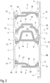
- FIG. 1 An embodiment of a profile design, such as this can be used, for example, as a panel element in a frame design for sectional door leaves, is shown.
- shell elements 1, 48 made of aluminum profile elements are shown on the side in the vertical area, which have a straight course on the inside and outside.
- the cavity is closed on the bottom by the composite molded body 2 and on the top by the composite body 5.
- the composite moldings 2 and 5 are provided at their lateral ends with clamping sections 3, which were connected to the shell elements 1 in a non-positive and positive manner in a manufacturing process.
- Such a manufacturing process creates a statically determined, stable frame design for the sectional door leaves, in which essentially the same profile designs are used in the vertical and horizontal sections.
- the underside composite molded body 2 has an open connection area 18, which can be used, for example, for a sealing element.
- the top-side composite molded body 5 can at the same time be designed in such a way that, for example, a mounting strip 27 can be received in an incision 19 of the composite molded body 5 on the right side.
- the mounting strip 27 rests with a contact leg 26 on a side surface of a plate-shaped insert element 45.
- Such an insert element 45 can consist, for example, of an insulating unit of Plexiglas panes or the like.
- the opposite surface of the insert element 45 rests against a sealing element 25 which is inserted into a fastening section 13.
- the sealing element 25 is inserted within a sealing receptacle 4 of the fastening section 13, which lies in the shell element 1, 48 outside the cavity.
- the cavity formed by the shell elements 1, 48 and the composite moldings 2, 5 is completely free. This means that the weight that is generated in a frame formation by the combination of shell elements 1 and composite moldings 2 and 5 is significantly reduced compared to known frames for a frame formation made from these for a panel element of a sectional door.
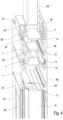
- FIG. 2 A possible combination of differently designed frame structures for panel elements of a sectional door leaf can be Figure 2 be removed.
- An upper panel element with another lower panel element is shown schematically there. These two panel elements are connected to one another, for example, via hinged connections (not shown).
- Both frame designs of the panel elements are constructed using shell elements 1.
- the shell elements 1 and 48 each have lateral fastening sections 13, via which the clamping sections 3 of the composite moldings 5, 7 are connected in a force-fitting and positive manner.
- the lower frame formation shown under the upper frame formation has the composite molding 7, which projects into a recess of the upper panel element.
- This composite molded body 7 has a cavity 15 that is closed on all sides and has an approximately trapezoidal, protruding design.
- a connecting wall 14 forms the lower end of the trapezoidal shape around the cavity 15. At the end, the connecting wall 14 merges into offsets 8 on each side, which are then followed by the clamping sections 3.
- the lower end between the side shell elements 1, 48 is completed by the composite molding 5, which also via offsets 8 into the clamping sections 3 in order to enter into a force-fitting and positive connection via the connecting sections 13 with the shell elements 1.
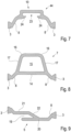
- the shape of the composite moldings 2, 5, 7, 44 already shown as examples is unlimited.
- the different shape designs have the task of making it possible to create a functional connection between two frame designs or a frame design and a known panel element.
- the composite molded body 44 has a cross section Figure 7 a substantially straight intermediate region 10, which merges laterally into the offsets 8. Following the offsets 8, the clamping sections 3 are shown.
- Below the intermediate area 10 is an opening area 23, which represents a partial opening of this composite molded body 44 through lateral projections 24. A seal can be inserted into the opening area 23 in order to be able to create a sealing transition compared to the trapezoidal shape of the composite molding 7, for example.
- the composite molding 7, which is exemplary in the Figure 8 is reproduced shows the enclosed cavity 15 with the essentially outer trapezoidal shape.
- the lateral, angled offsets 8 with the adjoining clamping sections 3 are formed.
- a side wall 17 leads up on each side, which forms the trapezoidal shape via lateral, rounded sections 16 and a straight section in between.
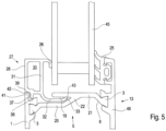
- FIG. 4 An example is given in the Figure 4 an embodiment of two frame designs for panel elements arranged one above the other is shown in a sectional view.
- the plate-shaped insert element 45 is held on the left side by the mounting strip 27 and on the opposite side by the sealing element 25 with the shell element 1, 48.
- a further panel element is indicated in a frame formation, which can also contain insert elements 45 in a plate-shaped design in its infill. As with the upper frame design, these can be mounted and dismantled using the mounting strips 27.
- the mounting strip 27 has, for example, a substantially rectangular cavity 30, which has an upper wall 29 on the top and an outer wall 28 on the bottom and an intermediate wall 31 on the inside.
- the lower end of the cavity 30 is formed by an unspecified connection between the outer wall 28 and the intermediate wall 31.
- An outwardly directed holding leg 36 is formed on the intermediate wall 31.
- a shoulder 37 is present on the holding leg 36.
- the lower end of the outer wall 28 forms a support 39, which is provided with an outwardly directed free cut 40 opposite the connection between the outer wall 28 and the intermediate wall 31.
- the projecting clamping leg 32 is formed underneath, which extends from the intermediate wall 31 over a radius into a substantially the leg area that has just been executed.
- the clamping leg 32 has an extension 33 which is slightly angled towards the free end of the contact leg 26.
- the contact leg 26 Continuing the upper wall 29 is the contact leg 26, which projects over a radius 34. This creates a free space 35 between the contact leg 26 and the intermediate wall 31, which is necessary in order to generate sufficient pressure against the surface of the insert element 45.
- the use of the in the Figure 6 Mounting strip 27 shown in a separate illustration.
- the clamping leg 32 of the mounting strip 27 engages in the incision 19 with its extension 33.
- the approach 33 is supported with a support point 43 against the cantilevered leg 20.
- the contact leg 26 rests against the insert element 45. So that the corresponding pressure of the contact leg 26 against the surface of the plate-shaped insert element 45 is maintained, the mounting strip 27 has the support 39, which is supported against a support point 42 of the shell element 1.
- the shell element 1 has a small projection 41, which is followed by a free space.
- the holding leg 36 of the mounting strip 27 is immersed in the free space, with the extension 37 at the same time being placed behind the projection 41 of the shell element 1.
Landscapes
- Engineering & Computer Science (AREA)
- Civil Engineering (AREA)
- Structural Engineering (AREA)
- Wing Frames And Configurations (AREA)
Applications Claiming Priority (1)
| Application Number | Priority Date | Filing Date | Title |
|---|---|---|---|
| DE102022113448 | 2022-05-27 |
Publications (2)
| Publication Number | Publication Date |
|---|---|
| EP4283086A1 true EP4283086A1 (fr) | 2023-11-29 |
| EP4283086B1 EP4283086B1 (fr) | 2024-10-30 |
Family
ID=86605249
Family Applications (1)
| Application Number | Title | Priority Date | Filing Date |
|---|---|---|---|
| EP23175695.8A Active EP4283086B1 (fr) | 2022-05-27 | 2023-05-26 | Structure de cadre comme élément de panneau pour une lame de porte sectionnelle |
Country Status (6)
| Country | Link |
|---|---|
| EP (1) | EP4283086B1 (fr) |
| DE (1) | DE102023113973A1 (fr) |
| DK (1) | DK4283086T3 (fr) |
| ES (1) | ES3007990T3 (fr) |
| FI (1) | FI4283086T3 (fr) |
| PL (1) | PL4283086T3 (fr) |
Cited By (1)
| Publication number | Priority date | Publication date | Assignee | Title |
|---|---|---|---|---|
| EP4640985A1 (fr) * | 2024-04-24 | 2025-10-29 | Alpha Deuren International BV | Vantail de porte sectionnelle |
Citations (9)
| Publication number | Priority date | Publication date | Assignee | Title |
|---|---|---|---|---|
| DE29517469U1 (de) | 1995-05-27 | 1996-01-11 | Technoform Caprano + Brunnhofer KG, 34277 Fuldabrück | Durch Strangpressen mit Hilfe eines Extruders hergestellter Profilstab aus einem thermoplastischen Kunststoff der Gruppe Polyolefine |
| EP0787882A2 (fr) * | 1995-08-17 | 1997-08-06 | Lindpointner Tore Gesellschaft M.B.H. | Vantail de porte sectionnelle |
| US20080282627A1 (en) | 2007-05-16 | 2008-11-20 | Three Rivers Aluminum Company D/B/A Traco | Construction product having a frame with multi-functional thermal break |
| EP2666948A1 (fr) | 2012-05-21 | 2013-11-27 | Hörmann KG Brockhagen | Agencement de cadre pour un panneau de porte sectionnelle |
| DE202018103416U1 (de) | 2018-05-22 | 2019-08-23 | Krispol Sp.z.o.o. | Sektionaltor mit anhubbarem Torblatt |
| DE202019105111U1 (de) * | 2019-05-21 | 2020-08-24 | Krispol Sp.z.o.o. | Sektionaltor mit Hubflügel |
| EP3751086A1 (fr) * | 2019-06-11 | 2020-12-16 | Hörmann KG Brockhagen | Porte sectionelle |
| WO2021209536A1 (fr) | 2020-04-16 | 2021-10-21 | Assa Abloy Entrance Systems Ab | Système d'entrée |
| EP3636870B1 (fr) | 2018-10-08 | 2021-12-08 | Ensinger GmbH | Procédé de fabrication d'un profilé isolant |
-
2023
- 2023-05-26 EP EP23175695.8A patent/EP4283086B1/fr active Active
- 2023-05-26 PL PL23175695.8T patent/PL4283086T3/pl unknown
- 2023-05-26 DE DE102023113973.8A patent/DE102023113973A1/de not_active Ceased
- 2023-05-26 ES ES23175695T patent/ES3007990T3/es active Active
- 2023-05-26 DK DK23175695.8T patent/DK4283086T3/da active
- 2023-05-26 FI FIEP23175695.8T patent/FI4283086T3/fi active
Patent Citations (9)
| Publication number | Priority date | Publication date | Assignee | Title |
|---|---|---|---|---|
| DE29517469U1 (de) | 1995-05-27 | 1996-01-11 | Technoform Caprano + Brunnhofer KG, 34277 Fuldabrück | Durch Strangpressen mit Hilfe eines Extruders hergestellter Profilstab aus einem thermoplastischen Kunststoff der Gruppe Polyolefine |
| EP0787882A2 (fr) * | 1995-08-17 | 1997-08-06 | Lindpointner Tore Gesellschaft M.B.H. | Vantail de porte sectionnelle |
| US20080282627A1 (en) | 2007-05-16 | 2008-11-20 | Three Rivers Aluminum Company D/B/A Traco | Construction product having a frame with multi-functional thermal break |
| EP2666948A1 (fr) | 2012-05-21 | 2013-11-27 | Hörmann KG Brockhagen | Agencement de cadre pour un panneau de porte sectionnelle |
| DE202018103416U1 (de) | 2018-05-22 | 2019-08-23 | Krispol Sp.z.o.o. | Sektionaltor mit anhubbarem Torblatt |
| EP3636870B1 (fr) | 2018-10-08 | 2021-12-08 | Ensinger GmbH | Procédé de fabrication d'un profilé isolant |
| DE202019105111U1 (de) * | 2019-05-21 | 2020-08-24 | Krispol Sp.z.o.o. | Sektionaltor mit Hubflügel |
| EP3751086A1 (fr) * | 2019-06-11 | 2020-12-16 | Hörmann KG Brockhagen | Porte sectionelle |
| WO2021209536A1 (fr) | 2020-04-16 | 2021-10-21 | Assa Abloy Entrance Systems Ab | Système d'entrée |
Cited By (1)
| Publication number | Priority date | Publication date | Assignee | Title |
|---|---|---|---|---|
| EP4640985A1 (fr) * | 2024-04-24 | 2025-10-29 | Alpha Deuren International BV | Vantail de porte sectionnelle |
Also Published As
| Publication number | Publication date |
|---|---|
| FI4283086T3 (fi) | 2025-01-10 |
| ES3007990T3 (en) | 2025-03-21 |
| DK4283086T3 (da) | 2025-01-02 |
| PL4283086T3 (pl) | 2025-05-19 |
| DE102023113973A1 (de) | 2023-11-30 |
| EP4283086B1 (fr) | 2024-10-30 |
Similar Documents
| Publication | Publication Date | Title |
|---|---|---|
| EP0153758A2 (fr) | Barre composée, en particulier pour châssis de fenêtre, châssis de porte et volets à rouleau | |
| DE69530150T2 (de) | Aus einer Verglasung und einem Längsträger oder einem auf der Verglasung aufgeklebten Beschlag bestehendes Konstruktionselement | |
| WO2001007745A9 (fr) | Porte coupe-feu pourvue d'un chassis de porte l'entourant | |
| DE102004011717A1 (de) | Haustür-Türblatt, damit versehene Haustür und Herstellverfahren dafür | |
| EP2666948A1 (fr) | Agencement de cadre pour un panneau de porte sectionnelle | |
| EP4283086B1 (fr) | Structure de cadre comme élément de panneau pour une lame de porte sectionnelle | |
| DE19963233A1 (de) | Rahmen für Fenster oder Türe | |
| EP2754842B1 (fr) | Profil d'étanchéité pour un profil de cadre et profil de cadre | |
| DE69509450T2 (de) | Seitenscheibe mit hohenverstellbarer Position für Kraftfahrzeuge | |
| EP1070820B1 (fr) | Fenêtre | |
| EP3553268A1 (fr) | Battant de porte, porte et procédé de fabrication de battant de porte | |
| EP4299871B1 (fr) | Structure de cadre faisant partie d'un élément de panneau pour une lame de porte sectionnelle | |
| AT390473B (de) | Profilrahmen fuer schiebetueren oder -fenster | |
| AT501873A1 (de) | Profil und verfahren zu dessen herstellung | |
| DE202004000817U1 (de) | Rahmenkörper aus einem hohlen, stranggepreßten Kunststoffprofil für Fenster und Türen | |
| EP0477544B1 (fr) | Pièce de remplissage pour parcloses | |
| DE4004698C1 (en) | Building window-frame construction - includes glass-strip weather bar fitting on frame bars or glass wall | |
| EP0869252B1 (fr) | Dispositif de fixage par engagement de force et/ou de forme de profilés sur un cadre ou vantail de porte ou fenêtre | |
| DE2030746A1 (de) | Fensterrahmen aus Kunststoff mit einer Verstärkungseinlage, welche zugleich Zentralverschluß ist | |
| EP3336296B1 (fr) | Cale de vitrage ainsi que battant de fenêtre ou de porte comportant une telle cale | |
| DE102008047642A1 (de) | Tür | |
| EP4283085A1 (fr) | Corps moulé composite pour éléments profilés en aluminium d'un élément de panneau d'une lame de porte sectionnelle | |
| DE202005007514U1 (de) | Rahmen für ein Fenster oder eine Tür | |
| EP0480290A1 (fr) | Vantail pour porte sectionnelle ou repliante, en particulier pour garages ou hangars, avec profilés de renfort | |
| EP4640985A1 (fr) | Vantail de porte sectionnelle |
Legal Events
| Date | Code | Title | Description |
|---|---|---|---|
| PUAI | Public reference made under article 153(3) epc to a published international application that has entered the european phase |
Free format text: ORIGINAL CODE: 0009012 |
|
| STAA | Information on the status of an ep patent application or granted ep patent |
Free format text: STATUS: THE APPLICATION HAS BEEN PUBLISHED |
|
| AK | Designated contracting states |
Kind code of ref document: A1 Designated state(s): AL AT BE BG CH CY CZ DE DK EE ES FI FR GB GR HR HU IE IS IT LI LT LU LV MC ME MK MT NL NO PL PT RO RS SE SI SK SM TR |
|
| STAA | Information on the status of an ep patent application or granted ep patent |
Free format text: STATUS: REQUEST FOR EXAMINATION WAS MADE |
|
| 17P | Request for examination filed |
Effective date: 20240527 |
|
| RBV | Designated contracting states (corrected) |
Designated state(s): AL AT BE BG CH CY CZ DE DK EE ES FI FR GB GR HR HU IE IS IT LI LT LU LV MC ME MK MT NL NO PL PT RO RS SE SI SK SM TR |
|
| GRAP | Despatch of communication of intention to grant a patent |
Free format text: ORIGINAL CODE: EPIDOSNIGR1 |
|
| STAA | Information on the status of an ep patent application or granted ep patent |
Free format text: STATUS: GRANT OF PATENT IS INTENDED |
|
| RIC1 | Information provided on ipc code assigned before grant |
Ipc: E06B 3/263 20060101ALI20240614BHEP Ipc: E06B 3/48 20060101AFI20240614BHEP |
|
| INTG | Intention to grant announced |
Effective date: 20240718 |
|
| GRAS | Grant fee paid |
Free format text: ORIGINAL CODE: EPIDOSNIGR3 |
|
| GRAA | (expected) grant |
Free format text: ORIGINAL CODE: 0009210 |
|
| STAA | Information on the status of an ep patent application or granted ep patent |
Free format text: STATUS: THE PATENT HAS BEEN GRANTED |
|
| RIN1 | Information on inventor provided before grant (corrected) |
Inventor name: PANNEKOEK, DENNIS |
|
| AK | Designated contracting states |
Kind code of ref document: B1 Designated state(s): AL AT BE BG CH CY CZ DE DK EE ES FI FR GB GR HR HU IE IS IT LI LT LU LV MC ME MK MT NL NO PL PT RO RS SE SI SK SM TR |
|
| REG | Reference to a national code |
Ref country code: GB Ref legal event code: FG4D Free format text: NOT ENGLISH |
|
| REG | Reference to a national code |
Ref country code: CH Ref legal event code: EP |
|
| REG | Reference to a national code |
Ref country code: IE Ref legal event code: FG4D Free format text: LANGUAGE OF EP DOCUMENT: GERMAN |
|
| REG | Reference to a national code |
Ref country code: DE Ref legal event code: R096 Ref document number: 502023000242 Country of ref document: DE |
|
| REG | Reference to a national code |
Ref country code: DK Ref legal event code: T3 Effective date: 20241220 Ref country code: SE Ref legal event code: TRGR |
|
| REG | Reference to a national code |
Ref country code: FI Ref legal event code: FGE |
|
| REG | Reference to a national code |
Ref country code: NL Ref legal event code: FP |
|
| REG | Reference to a national code |
Ref country code: LT Ref legal event code: MG9D |
|
| REG | Reference to a national code |
Ref country code: ES Ref legal event code: FG2A Ref document number: 3007990 Country of ref document: ES Kind code of ref document: T3 Effective date: 20250321 |
|
| PG25 | Lapsed in a contracting state [announced via postgrant information from national office to epo] |
Ref country code: HR Free format text: LAPSE BECAUSE OF FAILURE TO SUBMIT A TRANSLATION OF THE DESCRIPTION OR TO PAY THE FEE WITHIN THE PRESCRIBED TIME-LIMIT Effective date: 20241030 Ref country code: IS Free format text: LAPSE BECAUSE OF FAILURE TO SUBMIT A TRANSLATION OF THE DESCRIPTION OR TO PAY THE FEE WITHIN THE PRESCRIBED TIME-LIMIT Effective date: 20250228 Ref country code: PT Free format text: LAPSE BECAUSE OF FAILURE TO SUBMIT A TRANSLATION OF THE DESCRIPTION OR TO PAY THE FEE WITHIN THE PRESCRIBED TIME-LIMIT Effective date: 20250228 |
|
| PG25 | Lapsed in a contracting state [announced via postgrant information from national office to epo] |
Ref country code: BG Free format text: LAPSE BECAUSE OF FAILURE TO SUBMIT A TRANSLATION OF THE DESCRIPTION OR TO PAY THE FEE WITHIN THE PRESCRIBED TIME-LIMIT Effective date: 20241030 |
|
| PG25 | Lapsed in a contracting state [announced via postgrant information from national office to epo] |
Ref country code: GR Free format text: LAPSE BECAUSE OF FAILURE TO SUBMIT A TRANSLATION OF THE DESCRIPTION OR TO PAY THE FEE WITHIN THE PRESCRIBED TIME-LIMIT Effective date: 20250131 Ref country code: LV Free format text: LAPSE BECAUSE OF FAILURE TO SUBMIT A TRANSLATION OF THE DESCRIPTION OR TO PAY THE FEE WITHIN THE PRESCRIBED TIME-LIMIT Effective date: 20241030 |
|
| PG25 | Lapsed in a contracting state [announced via postgrant information from national office to epo] |
Ref country code: RS Free format text: LAPSE BECAUSE OF FAILURE TO SUBMIT A TRANSLATION OF THE DESCRIPTION OR TO PAY THE FEE WITHIN THE PRESCRIBED TIME-LIMIT Effective date: 20250130 |
|
| PG25 | Lapsed in a contracting state [announced via postgrant information from national office to epo] |
Ref country code: SM Free format text: LAPSE BECAUSE OF FAILURE TO SUBMIT A TRANSLATION OF THE DESCRIPTION OR TO PAY THE FEE WITHIN THE PRESCRIBED TIME-LIMIT Effective date: 20241030 |
|
| PGFP | Annual fee paid to national office [announced via postgrant information from national office to epo] |
Ref country code: DE Payment date: 20250521 Year of fee payment: 3 Ref country code: PL Payment date: 20250515 Year of fee payment: 3 |
|
| PGFP | Annual fee paid to national office [announced via postgrant information from national office to epo] |
Ref country code: DK Payment date: 20250526 Year of fee payment: 3 |
|
| PGFP | Annual fee paid to national office [announced via postgrant information from national office to epo] |
Ref country code: NO Payment date: 20250523 Year of fee payment: 3 |
|
| PGFP | Annual fee paid to national office [announced via postgrant information from national office to epo] |
Ref country code: BE Payment date: 20250521 Year of fee payment: 3 |
|
| PG25 | Lapsed in a contracting state [announced via postgrant information from national office to epo] |
Ref country code: EE Free format text: LAPSE BECAUSE OF FAILURE TO SUBMIT A TRANSLATION OF THE DESCRIPTION OR TO PAY THE FEE WITHIN THE PRESCRIBED TIME-LIMIT Effective date: 20241030 |
|
| PGFP | Annual fee paid to national office [announced via postgrant information from national office to epo] |
Ref country code: FR Payment date: 20250528 Year of fee payment: 3 |
|
| PG25 | Lapsed in a contracting state [announced via postgrant information from national office to epo] |
Ref country code: RO Free format text: LAPSE BECAUSE OF FAILURE TO SUBMIT A TRANSLATION OF THE DESCRIPTION OR TO PAY THE FEE WITHIN THE PRESCRIBED TIME-LIMIT Effective date: 20241030 |
|
| PGFP | Annual fee paid to national office [announced via postgrant information from national office to epo] |
Ref country code: AT Payment date: 20250721 Year of fee payment: 3 |
|
| PG25 | Lapsed in a contracting state [announced via postgrant information from national office to epo] |
Ref country code: SK Free format text: LAPSE BECAUSE OF FAILURE TO SUBMIT A TRANSLATION OF THE DESCRIPTION OR TO PAY THE FEE WITHIN THE PRESCRIBED TIME-LIMIT Effective date: 20241030 |
|
| PGFP | Annual fee paid to national office [announced via postgrant information from national office to epo] |
Ref country code: CZ Payment date: 20250520 Year of fee payment: 3 |
|
| PG25 | Lapsed in a contracting state [announced via postgrant information from national office to epo] |
Ref country code: IT Free format text: LAPSE BECAUSE OF FAILURE TO SUBMIT A TRANSLATION OF THE DESCRIPTION OR TO PAY THE FEE WITHIN THE PRESCRIBED TIME-LIMIT Effective date: 20241030 |
|
| PGFP | Annual fee paid to national office [announced via postgrant information from national office to epo] |
Ref country code: SE Payment date: 20250521 Year of fee payment: 3 |
|
| REG | Reference to a national code |
Ref country code: DE Ref legal event code: R097 Ref document number: 502023000242 Country of ref document: DE |
|
| PLBE | No opposition filed within time limit |
Free format text: ORIGINAL CODE: 0009261 |
|
| STAA | Information on the status of an ep patent application or granted ep patent |
Free format text: STATUS: NO OPPOSITION FILED WITHIN TIME LIMIT |
|
| 26N | No opposition filed |
Effective date: 20250731 |
|
| PGFP | Annual fee paid to national office [announced via postgrant information from national office to epo] |
Ref country code: ES Payment date: 20250630 Year of fee payment: 3 |
|
| PG25 | Lapsed in a contracting state [announced via postgrant information from national office to epo] |
Ref country code: FI Free format text: LAPSE BECAUSE OF NON-PAYMENT OF DUE FEES Effective date: 20250526 |
|
| PG25 | Lapsed in a contracting state [announced via postgrant information from national office to epo] |
Ref country code: LU Free format text: LAPSE BECAUSE OF NON-PAYMENT OF DUE FEES Effective date: 20250526 |
|
| PG25 | Lapsed in a contracting state [announced via postgrant information from national office to epo] |
Ref country code: MC Free format text: LAPSE BECAUSE OF FAILURE TO SUBMIT A TRANSLATION OF THE DESCRIPTION OR TO PAY THE FEE WITHIN THE PRESCRIBED TIME-LIMIT Effective date: 20241030 |
|
| PG25 | Lapsed in a contracting state [announced via postgrant information from national office to epo] |
Ref country code: IE Free format text: LAPSE BECAUSE OF NON-PAYMENT OF DUE FEES Effective date: 20250526 |