EP4283127A1 - Integrierte pumpen - Google Patents
Integrierte pumpen Download PDFInfo
- Publication number
- EP4283127A1 EP4283127A1 EP23174641.3A EP23174641A EP4283127A1 EP 4283127 A1 EP4283127 A1 EP 4283127A1 EP 23174641 A EP23174641 A EP 23174641A EP 4283127 A1 EP4283127 A1 EP 4283127A1
- Authority
- EP
- European Patent Office
- Prior art keywords
- fluid
- pump
- housing
- cylinder
- housing portion
- Prior art date
- Legal status (The legal status is an assumption and is not a legal conclusion. Google has not performed a legal analysis and makes no representation as to the accuracy of the status listed.)
- Pending
Links
Images



Classifications
-
- F—MECHANICAL ENGINEERING; LIGHTING; HEATING; WEAPONS; BLASTING
- F04—POSITIVE - DISPLACEMENT MACHINES FOR LIQUIDS; PUMPS FOR LIQUIDS OR ELASTIC FLUIDS
- F04D—NON-POSITIVE-DISPLACEMENT PUMPS
- F04D13/00—Pumping installations or systems
- F04D13/02—Units comprising pumps and their driving means
- F04D13/06—Units comprising pumps and their driving means the pump being electrically driven
- F04D13/0653—Units comprising pumps and their driving means the pump being electrically driven the motor being flooded
-
- F—MECHANICAL ENGINEERING; LIGHTING; HEATING; WEAPONS; BLASTING
- F04—POSITIVE - DISPLACEMENT MACHINES FOR LIQUIDS; PUMPS FOR LIQUIDS OR ELASTIC FLUIDS
- F04D—NON-POSITIVE-DISPLACEMENT PUMPS
- F04D5/00—Pumps with circumferential or transverse flow
- F04D5/002—Regenerative pumps
- F04D5/003—Regenerative pumps of multistage type
- F04D5/006—Regenerative pumps of multistage type the stages being axially offset
-
- F—MECHANICAL ENGINEERING; LIGHTING; HEATING; WEAPONS; BLASTING
- F04—POSITIVE - DISPLACEMENT MACHINES FOR LIQUIDS; PUMPS FOR LIQUIDS OR ELASTIC FLUIDS
- F04D—NON-POSITIVE-DISPLACEMENT PUMPS
- F04D13/00—Pumping installations or systems
- F04D13/02—Units comprising pumps and their driving means
- F04D13/06—Units comprising pumps and their driving means the pump being electrically driven
- F04D13/0606—Canned motor pumps
-
- F—MECHANICAL ENGINEERING; LIGHTING; HEATING; WEAPONS; BLASTING
- F04—POSITIVE - DISPLACEMENT MACHINES FOR LIQUIDS; PUMPS FOR LIQUIDS OR ELASTIC FLUIDS
- F04D—NON-POSITIVE-DISPLACEMENT PUMPS
- F04D29/00—Details, component parts, or accessories
- F04D29/40—Casings; Connections of working fluid
- F04D29/406—Casings; Connections of working fluid especially adapted for liquid pumps
-
- F—MECHANICAL ENGINEERING; LIGHTING; HEATING; WEAPONS; BLASTING
- F04—POSITIVE - DISPLACEMENT MACHINES FOR LIQUIDS; PUMPS FOR LIQUIDS OR ELASTIC FLUIDS
- F04D—NON-POSITIVE-DISPLACEMENT PUMPS
- F04D5/00—Pumps with circumferential or transverse flow
- F04D5/002—Regenerative pumps
-
- H—ELECTRICITY
- H02—GENERATION; CONVERSION OR DISTRIBUTION OF ELECTRIC POWER
- H02K—DYNAMO-ELECTRIC MACHINES
- H02K9/00—Arrangements for cooling or ventilating
- H02K9/02—Arrangements for cooling or ventilating by ambient air flowing through the machine
- H02K9/04—Arrangements for cooling or ventilating by ambient air flowing through the machine having means for generating a flow of cooling medium
Definitions
- the present disclosure relates to pumps, and more particularly to integrated pumps, e.g., for use in an aircraft fuel system.
- Certain pumps may include an electric motor coupled thereto.
- electric motors can be very heavy, therefore it is necessary to consider the weight tradeoff between a gearbox used to drive a pump with rotational power from an engine, for example, and the electric motor.
- improvements to pump systems such as in the aerospace industry, that allow for integration of electric motors into existing pumps but that address weight, cost, space considerations more efficiently than conventional electrically driven pumps. This disclosure provides a solution for this need.
- a pump in accordance with at least one aspect of this disclosure, includes a housing having one or more fluid inlets and one or more fluid outlets.
- the housing is configured to act as a pump housing for passing a fluid from the one or more fluid inlets to the one or more fluid outlets and configured to act as a stator for a motor.
- the pump also includes a cylinder encased within the housing and mounted on a shaft for rotation within the housing.
- the cylinder is configured to act as an impeller to drive fluid from the one or more fluid inlets through the housing to the one or more fluid outlets and configured to act as a rotor for the motor.
- the one or more fluid inlets and one or more fluid outlets can be spaced from one another along an outer diameter of the housing in a circumferential direction to form one or more circumferential passes within the housing.
- a first housing portion can include one or more field windings configured to generate a magnetic field to drive rotation of the cylinder.
- the first housing portion can be configured to act as the stator for the motor.
- only the first housing portion includes electrical components for the housing to act as a stator.
- the first housing portion and a second housing portion together can be configured to act as the pump housing to pass the fluid from the fluid inlet to the fluid outlet.
- the one or more fluid inlets can include two fluid inlets and the one or more fluid outlets can include two fluid outlets.
- One fluid inlet and one fluid outlet can be positioned on first side of the second housing portion. Additionally, one fluid inlet and one fluid outlet can be positioned on a second side of the second housing portion, opposite the first side and across the first housing portion.
- a fluid channel formed by the fluid inlet and the fluid outlet on the first side of the second housing portion can be in fluid communication with a fluid channel formed by the fluid inlet and the fluid outlet on the second side of the second housing portion via a clearance.
- the fluid passing though the housing and the clearance can be configured to act as coolant for the motor.
- the clearance can be formed radially between an outer diameter of the first cylinder portion and an inner diameter of the first housing portion. In certain embodiments, only the second housing portion can form the pump housing.
- the cylinder can include a first cylinder portion and a second cylinder portion.
- the first cylinder portion can be bound by the second cylinder portion along the rotational axis of the cylinder such that the first cylinder portion and the second cylinder portion are configured to rotate together.
- the pump and the motor are configured to act in parallel and simultaneously, where the motor drives the pump.
- the first cylinder portion can include one or more rotor poles configured to be driven by a magnetic field generated by the first housing portion such that the first cylinder portion is configured to act as the rotor for the electrical machine. In certain embodiments, only the first cylinder portion includes the electrical components needed for cylinder to act as the rotor.
- the second cylinder portion can include one or more blades configured to induce turbulence in a fluid passing from the one or more fluid inlets to the one or more fluid outlets, for example the second cylinder portion can include an impeller.
- the cylinder can include a rotor portion sandwiched between two impeller portions.
- the impeller portions can be configured to induce one or more radial vortex passes in a fluid passing though the one or more circumferential passes to increase a pressure of the fluid at the fluid outlet.
- the first cylinder portion, the rotor portion, and the first housing portion, the stator portion can have the same axial length.
- the second cylinder portion, the impeller portion(s) can extend axially beyond the first housing portion, the stator portion.
- One or more bearings can be disposed on the shaft configured to interface between the shaft and the second housing portion to reduce rotational friction between the shaft and the second housing portion.
- the pump can be or include a regenerative pump.
- at least a portion of the cylinder can be or include a regenerative impeller wheel.
- the motor can include a switched reluctance motor.
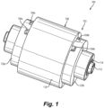
- FIG. 1 an illustrative view of an embodiment of a pump in accordance with the disclosure is shown in Fig. 1 and is designated generally by reference character 100.
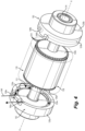
- FIG. 2-5 Other embodiments and/or aspects of this disclosure are shown in Figs. 2-5 .
- a pump 100 can include a housing 102 having one or more fluid inlets 104 and one or more fluid outlets 106.
- the housing 102 can be configured to act as both a pump housing for passing a fluid from the one or more fluid inlets 104 to the one or more fluid outlets 106 and configured to act as a stator for a motor 108 (e.g., a switched reluctance motor).
- the pump 100 can also include a cylinder 110 encased within the housing 102 and mounted on a shaft 112 for rotation within the housing.
- the cylinder 110 can be configured to act as both an impeller to drive fluid from the one or more fluid inlets 104 through the housing 102 to the one or more fluid outlets 106 and configured to act as a rotor for the motor 108.
- One or more bearings 114 can be disposed on the shaft 112 configured to interface between the shaft 112 and the housing to reduce rotational friction between the shaft 112 and the housing 102.
- the housing 102 can include a first housing portion 118 and a second housing portion 120.
- the first housing portion 118 is shown in phantom.
- the one or more fluid inlets 104 can include two fluid inlets 104a, 104b and the one or more fluid outlets 106 can include two fluid outlets 106a, 106b.
- One fluid inlet 104a and one fluid outlet 106a can be positioned on first side 120a of the second housing portion 120.
- one fluid inlet 104b and one fluid outlet 106b can be positioned on a second side 120b of the second housing portion 120, opposite the first side 120a and across the first housing portion 118.
- the first housing portion 118 can be configured to act as the stator of the motor 108 and can include one or more field windings 122 configured to generate a magnetic field to drive rotation of the cylinder 110. In certain embodiments, only the first housing portion 118 includes electrical components needed for the housing 102 as a whole to act as a stator.
- the second housing portion 120 can include one or more fluid channels 124 configured to form one or more plena 126 when coupled to the second housing portion 118. Because the plena 124 are formed by the coming together of the two housing portions 118, 120, the first housing portion 118 and the second housing portion 120 together can be configured to act as the pump housing 102 to pass the fluid from the fluid inlet 104 to the fluid outlet 106.
- first housing portion 118 can be bookended by first and second sides 120a, 120b of the second housing portion 120.
- One or more additional housing portions can be included as needed, for example an outer housing portion configured to enclose both first and second housing portions 118, 120, though the additional housing portions are not shown.
- the cylinder 110 can include a first cylinder portion 128 and a second cylinder portion 130.
- the first cylinder portion 128 can be bound on either or both sides by the second cylinder portion 130a, 130b along the rotational axis A of the cylinder 110 such that the first cylinder portion 128 and the second cylinder portion 130 are configured to rotate together.
- the cylinder 110 can include a rotor portion 128 sandwiched between two impeller portions 130a, 130b so that the pump 100 and the motor 108 are driven in parallel and simultaneously.
- the first cylinder portion e.g., the rotor portion
- the first cylinder portion can include one or more rotor poles 132 configured to be driven by the magnetic field generated by the first housing portion 118 such that the first cylinder portion 128 is configured to act as the rotor for the motor 108.
- only the first cylinder portion 128 can include the electrical components needed for cylinder 110 to act as the rotor.
- the second cylinder portion 130 can include one or more blades 134 configured to induce turbulence in a fluid passing from the one or more fluid inlets 104 to the one or more fluid outlets 106.
- at least a portion of the second cylinder portion 130 can be or include a regenerative impeller wheel.
- the first cylinder portion 128 e.g., the rotor portion
- the first housing portion 118 e.g., the stator portion
- the second cylinder portion 130, the impeller portion(s) can extend axially beyond the first housing portion 118.
- the fluid channel 124a, and/or the plena 126a formed by the fluid inlet 104a and the fluid outlet 106a on the first side 120a of the second housing portion 120 can be in fluid communication with a fluid channel 124b and/or a plena 126b formed by the fluid inlet 104b and the fluid outlet 106b on the second side 120b of the second housing portion 120 via a clearance 136.
- the clearance can 136 be formed radially between an outer diameter 138 of the first cylinder portion 128 and an inner diameter 140 of the first housing portion 118.
- the motor 108 can be a wet rotor motor where fluid passing though the housing 102 and the clearance 136 can be configured to act as coolant for the motor 108.
- the one or more fluid inlets 104 and one or more fluid outlets 106 can be spaced from one another along an outer diameter 142 of the housing in a circumferential direction to form one or more circumferential passes 144 within the housing 102.
- the impeller portions 130 of the cylinder 110 can be configured to induce one or more radial vortex passes 146 in the fluid passing though the one or more circumferential passes 144 to increase a pressure of the fluid at the fluid outlet 106. With each pass, kinetic energy is added to the fluid stream by the blades 134, which translates to an increase of the pump discharge pressure.
- the radial vortex passes 144 can occur within the plena 126 formed by the the coming together of the two housing portions 118, 120, as shown.
- Embodiments can include a regenerative pump wheel having vanes which closely resemble the rotor teeth of a switched reluctance rotor.
- Certain design variations to the pump allow for the integration of an electric motor rotor where the pump wheel becomes an electric motor coupling device in a stator field. These design variations and integration of the electric motor rotor do not impact pump performance.
- integration of the pump wheel and the motor rotor can provide a significant weight, cost, and envelop reduction. Therefore, embodiments of the pump provided herein can be favorably than a standalone pump/motor combination.
- the impeller portion is split into two mirror image pumping elements, the resulting two regen pumping elements produce the same pumping action, which can further increase pressure at the discharge outlet.
- any suitable pump and motor design can be used.
- other vane pumps, motors having an open loop commutation, or a permanent magnet rotor may be used or included. It should be appreciated by those skilled in the art that variations in design may occur if integrating certain pump types with certain motors, however the principle as described herein should remain the same.
- any numerical values disclosed herein can be exact values or can be values within a range. Further, any terms of approximation (e.g., “about”, “approximately”, “around”) used in this disclosure can mean the stated value within a range. For example, in certain embodiments, the range can be within (plus or minus) 20%, or within 10%, or within 5%, or within 2%, or within any other suitable percentage or number as appreciated by those having ordinary skill in the art (e.g., for known tolerance limits or error ranges).
- a reference to "A and/or B", when used in conjunction with open-ended language such as “comprising” can refer, in one embodiment, to A only (optionally including elements other than B); in another embodiment, to B only (optionally including elements other than A); in yet another embodiment, to both A and B (optionally including other elements); etc.
Landscapes
- Engineering & Computer Science (AREA)
- Mechanical Engineering (AREA)
- General Engineering & Computer Science (AREA)
- Structures Of Non-Positive Displacement Pumps (AREA)
Applications Claiming Priority (1)
| Application Number | Priority Date | Filing Date | Title |
|---|---|---|---|
| US17/750,377 US11946471B2 (en) | 2022-05-22 | 2022-05-22 | Integrated pumps |
Publications (1)
| Publication Number | Publication Date |
|---|---|
| EP4283127A1 true EP4283127A1 (de) | 2023-11-29 |
Family
ID=86497666
Family Applications (1)
| Application Number | Title | Priority Date | Filing Date |
|---|---|---|---|
| EP23174641.3A Pending EP4283127A1 (de) | 2022-05-22 | 2023-05-22 | Integrierte pumpen |
Country Status (2)
| Country | Link |
|---|---|
| US (1) | US11946471B2 (de) |
| EP (1) | EP4283127A1 (de) |
Citations (5)
| Publication number | Priority date | Publication date | Assignee | Title |
|---|---|---|---|---|
| US3347168A (en) * | 1966-02-16 | 1967-10-17 | Westinghouse Electric Corp | Motor pump unit |
| US3500755A (en) * | 1968-05-17 | 1970-03-17 | Crane Co | Combined drag pump and electric motor |
| JPS60150498A (ja) * | 1984-01-18 | 1985-08-08 | Nippon Radiator Co Ltd | ブラシレスモ−タ式ポンプ |
| DE19752884A1 (de) * | 1997-11-28 | 1999-06-10 | Bosch Gmbh Robert | Förderaggregat für Kraftstoff |
| DE19937012A1 (de) * | 1999-08-05 | 2001-02-08 | Bosch Gmbh Robert | Förderaggregat für Kraftstoff |
Family Cites Families (28)
| Publication number | Priority date | Publication date | Assignee | Title |
|---|---|---|---|---|
| US1794649A (en) * | 1929-01-31 | 1931-03-03 | Fairbanks Morse & Co | Protecting and cooling means for dynamo-electric machines |
| US1961387A (en) * | 1930-08-19 | 1934-06-05 | U S Electrical Mfg Company | Ventilated motor |
| US2074067A (en) * | 1935-10-14 | 1937-03-16 | Master Electric Co | Ventilated splashproof motor housing |
| US2193408A (en) * | 1937-03-10 | 1940-03-12 | Allis Chalmers Mfg Co | Dynamo-electric machine |
| US2429903A (en) * | 1943-10-19 | 1947-10-28 | Singer Mfg Co | Ventilation of small electric motors |
| US2528154A (en) * | 1947-03-13 | 1950-10-31 | Westinghouse Electric Corp | Shrunk rotor for squirrel-cage motors |
| US2515973A (en) * | 1948-12-17 | 1950-07-18 | Westinghouse Electric Corp | Totally enclosed motor |
| US2842062A (en) * | 1951-10-31 | 1958-07-08 | Pratt & Whitney Co Inc | Vortex pump |
| US2685658A (en) * | 1952-11-05 | 1954-08-03 | Gen Electric | Dynamoelectric machine |
| US2777079A (en) * | 1953-09-23 | 1957-01-08 | Westinghouse Electric Corp | Outdoor motor |
| US2825827A (en) * | 1955-02-14 | 1958-03-04 | Us Electrical Motors Inc | Ventilated electric motor |
| US3075106A (en) * | 1961-03-09 | 1963-01-22 | Gen Electric | Dynamoelectric machine |
| US3356111A (en) * | 1961-10-31 | 1967-12-05 | Rockwell Mfg Co | Power tool improvements |
| US3143897A (en) * | 1962-05-29 | 1964-08-11 | Gen Electric | Gear mechanisms and method of making the same |
| US3243617A (en) * | 1963-01-02 | 1966-03-29 | Gen Electric | Dynamoelectric machine |
| US3250926A (en) * | 1963-04-11 | 1966-05-10 | Emerson Electric Co | Ventilated motor |
| FR1492181A (fr) * | 1966-06-20 | 1967-08-18 | Materiel Telephonique | Bloc pompe-moteur |
| US3518467A (en) * | 1968-11-04 | 1970-06-30 | Emerson Electric Co | Totally enclosed fan-cooled electric motor |
| US3518468A (en) * | 1968-11-14 | 1970-06-30 | Emerson Electric Co | Electric motor cooling construction |
| GB2036870A (en) * | 1978-12-15 | 1980-07-02 | Utile Eng Co Ltd | Regenerative Turbo Machine |
| DE4128150A1 (de) * | 1991-08-24 | 1993-02-25 | Duerr Dental Gmbh Co Kg | Saugmaschine, insbesondere fuer dentalen einsatz |
| DE4336090C2 (de) * | 1993-10-22 | 2001-10-04 | Bosch Gmbh Robert | Aggregat zum Fördern von Kraftstoff aus einem Vorratsbehälter zur Brennkraftmaschine eines Kraftfahrzeuges |
| US6280157B1 (en) * | 1999-06-29 | 2001-08-28 | Flowserve Management Company | Sealless integral-motor pump with regenerative impeller disk |
| ITPN20010005A1 (it) | 2001-01-25 | 2002-07-25 | Sole Spa | Motopompa |
| US7232292B2 (en) | 2001-08-21 | 2007-06-19 | Rotys Inc. | Integrated motorized pump |
| JP2003232289A (ja) | 2002-02-12 | 2003-08-22 | Nidec Shibaura Corp | ポンプ及びそのポンプを用いたタンク |
| DE10317010A1 (de) * | 2003-04-11 | 2004-11-04 | Schmitt-Kreiselpumpen Gmbh & Co. Kg | Wirbelpumpe |
| US9162019B2 (en) * | 2006-04-26 | 2015-10-20 | The Cleveland Clinic Foundation | Two-stage rotodynamic blood pump |
-
2022
- 2022-05-22 US US17/750,377 patent/US11946471B2/en active Active
-
2023
- 2023-05-22 EP EP23174641.3A patent/EP4283127A1/de active Pending
Patent Citations (5)
| Publication number | Priority date | Publication date | Assignee | Title |
|---|---|---|---|---|
| US3347168A (en) * | 1966-02-16 | 1967-10-17 | Westinghouse Electric Corp | Motor pump unit |
| US3500755A (en) * | 1968-05-17 | 1970-03-17 | Crane Co | Combined drag pump and electric motor |
| JPS60150498A (ja) * | 1984-01-18 | 1985-08-08 | Nippon Radiator Co Ltd | ブラシレスモ−タ式ポンプ |
| DE19752884A1 (de) * | 1997-11-28 | 1999-06-10 | Bosch Gmbh Robert | Förderaggregat für Kraftstoff |
| DE19937012A1 (de) * | 1999-08-05 | 2001-02-08 | Bosch Gmbh Robert | Förderaggregat für Kraftstoff |
Also Published As
| Publication number | Publication date |
|---|---|
| US20230374991A1 (en) | 2023-11-23 |
| US11946471B2 (en) | 2024-04-02 |
Similar Documents
| Publication | Publication Date | Title |
|---|---|---|
| US8749105B2 (en) | Magnetic inductor rotary machine and fluid transfer apparatus that uses the same | |
| EP3387741B1 (de) | Ein elektromotor | |
| KR101164576B1 (ko) | 전동 과급기 | |
| EP3759794B1 (de) | Bürstenloser motor | |
| CN101715624B (zh) | 用于发电机的两级冷却风扇 | |
| EP0169682A2 (de) | Fluidmaschine | |
| CN104303397B (zh) | 真空泵用ipm马达 | |
| WO2014038202A1 (ja) | 輸送機械用の電動圧縮機 | |
| KR102631485B1 (ko) | 유체를 통과시키기 위한 회전자 및 고정자를 포함하는 회전식 전기 기계 | |
| EP3713051A1 (de) | Rotoranordnung und kühlverfahren | |
| NO347974B1 (en) | Improved arrangement for pressurizing of fluid | |
| CN114825827A (zh) | 电机、驱动系统以及该驱动系统的用途 | |
| CN100431242C (zh) | 电机转子通风装置 | |
| CN111628589A (zh) | 旋转电机 | |
| WO2021100292A1 (ja) | スロットレス型電動機、電動送風機および電気掃除機 | |
| GB2542247A (en) | Axial-flux induction motor pump | |
| EP4283127A1 (de) | Integrierte pumpen | |
| US20240396403A1 (en) | Hollow shaft for a rotor of electric motor | |
| EP4328454A1 (de) | Rotorintegrierter axialflusselektromotor | |
| EP4328453A1 (de) | Rotorintegrierter axialflusselektromotor | |
| CN110383649B (zh) | 电机的冷却 | |
| US20230299643A1 (en) | Rotating machine with cooling fan | |
| CN110556973B (zh) | 用于冷却电机的系统 | |
| JP7137543B2 (ja) | 回転電機 | |
| CN114374305B (zh) | 自启动三相同步磁阻电动机转子 |
Legal Events
| Date | Code | Title | Description |
|---|---|---|---|
| PUAI | Public reference made under article 153(3) epc to a published international application that has entered the european phase |
Free format text: ORIGINAL CODE: 0009012 |
|
| STAA | Information on the status of an ep patent application or granted ep patent |
Free format text: STATUS: THE APPLICATION HAS BEEN PUBLISHED |
|
| AK | Designated contracting states |
Kind code of ref document: A1 Designated state(s): AL AT BE BG CH CY CZ DE DK EE ES FI FR GB GR HR HU IE IS IT LI LT LU LV MC ME MK MT NL NO PL PT RO RS SE SI SK SM TR |
|
| STAA | Information on the status of an ep patent application or granted ep patent |
Free format text: STATUS: REQUEST FOR EXAMINATION WAS MADE |
|
| 17P | Request for examination filed |
Effective date: 20240529 |
|
| RBV | Designated contracting states (corrected) |
Designated state(s): AL AT BE BG CH CY CZ DE DK EE ES FI FR GB GR HR HU IE IS IT LI LT LU LV MC ME MK MT NL NO PL PT RO RS SE SI SK SM TR |
|
| STAA | Information on the status of an ep patent application or granted ep patent |
Free format text: STATUS: EXAMINATION IS IN PROGRESS |
|
| 17Q | First examination report despatched |
Effective date: 20250918 |