EP4283190A1 - Accessoire de connecteur et générateur de vapeur le comprenant - Google Patents
Accessoire de connecteur et générateur de vapeur le comprenant Download PDFInfo
- Publication number
- EP4283190A1 EP4283190A1 EP22175073.0A EP22175073A EP4283190A1 EP 4283190 A1 EP4283190 A1 EP 4283190A1 EP 22175073 A EP22175073 A EP 22175073A EP 4283190 A1 EP4283190 A1 EP 4283190A1
- Authority
- EP
- European Patent Office
- Prior art keywords
- steam
- water
- steam generator
- housing
- hose
- Prior art date
- Legal status (The legal status is an assumption and is not a legal conclusion. Google has not performed a legal analysis and makes no representation as to the accuracy of the status listed.)
- Withdrawn
Links
- XLYOFNOQVPJJNP-UHFFFAOYSA-N water Substances O XLYOFNOQVPJJNP-UHFFFAOYSA-N 0.000 claims abstract description 191
- 239000000463 material Substances 0.000 claims description 34
- 238000010025 steaming Methods 0.000 claims description 27
- 239000004033 plastic Substances 0.000 claims description 20
- 239000004811 fluoropolymer Substances 0.000 claims description 14
- 229920002313 fluoropolymer Polymers 0.000 claims description 14
- 239000012530 fluid Substances 0.000 claims description 8
- 238000004891 communication Methods 0.000 claims description 7
- 230000014759 maintenance of location Effects 0.000 claims description 6
- 238000009825 accumulation Methods 0.000 description 7
- 238000000034 method Methods 0.000 description 7
- 238000012360 testing method Methods 0.000 description 6
- 239000004677 Nylon Substances 0.000 description 5
- 239000011521 glass Substances 0.000 description 5
- 229920001778 nylon Polymers 0.000 description 5
- 238000013461 design Methods 0.000 description 4
- 239000004952 Polyamide Substances 0.000 description 3
- 239000013536 elastomeric material Substances 0.000 description 3
- 230000005484 gravity Effects 0.000 description 3
- 238000004519 manufacturing process Methods 0.000 description 3
- 229920002647 polyamide Polymers 0.000 description 3
- 239000004411 aluminium Substances 0.000 description 2
- 229910052782 aluminium Inorganic materials 0.000 description 2
- XAGFODPZIPBFFR-UHFFFAOYSA-N aluminium Chemical compound [Al] XAGFODPZIPBFFR-UHFFFAOYSA-N 0.000 description 2
- 238000013459 approach Methods 0.000 description 2
- 238000005266 casting Methods 0.000 description 2
- 230000001351 cycling effect Effects 0.000 description 2
- 230000008021 deposition Effects 0.000 description 2
- 238000004512 die casting Methods 0.000 description 2
- 238000010409 ironing Methods 0.000 description 2
- 238000000465 moulding Methods 0.000 description 2
- 239000002245 particle Substances 0.000 description 2
- 238000011144 upstream manufacturing Methods 0.000 description 2
- 230000008016 vaporization Effects 0.000 description 2
- 238000009834 vaporization Methods 0.000 description 2
- 230000000903 blocking effect Effects 0.000 description 1
- 230000001010 compromised effect Effects 0.000 description 1
- 230000001419 dependent effect Effects 0.000 description 1
- 238000010438 heat treatment Methods 0.000 description 1
- 238000010832 independent-sample T-test Methods 0.000 description 1
- 238000003780 insertion Methods 0.000 description 1
- 230000037431 insertion Effects 0.000 description 1
- 238000005304 joining Methods 0.000 description 1
- 239000007769 metal material Substances 0.000 description 1
- 230000001681 protective effect Effects 0.000 description 1
- 238000007789 sealing Methods 0.000 description 1
- 229920002379 silicone rubber Polymers 0.000 description 1
- 239000004945 silicone rubber Substances 0.000 description 1
- 238000012546 transfer Methods 0.000 description 1
Images




Classifications
-
- F—MECHANICAL ENGINEERING; LIGHTING; HEATING; WEAPONS; BLASTING
- F22—STEAM GENERATION
- F22B—METHODS OF STEAM GENERATION; STEAM BOILERS
- F22B1/00—Methods of steam generation characterised by form of heating method
- F22B1/28—Methods of steam generation characterised by form of heating method in boilers heated electrically
- F22B1/284—Methods of steam generation characterised by form of heating method in boilers heated electrically with water in reservoirs
-
- D—TEXTILES; PAPER
- D06—TREATMENT OF TEXTILES OR THE LIKE; LAUNDERING; FLEXIBLE MATERIALS NOT OTHERWISE PROVIDED FOR
- D06F—LAUNDERING, DRYING, IRONING, PRESSING OR FOLDING TEXTILE ARTICLES
- D06F75/00—Hand irons
- D06F75/08—Hand irons internally heated by electricity
- D06F75/10—Hand irons internally heated by electricity with means for supplying steam to the article being ironed
- D06F75/12—Hand irons internally heated by electricity with means for supplying steam to the article being ironed the steam being produced from water supplied to the iron from an external source
Definitions
- the invention relates to a connector attachment for attaching to a housing of a steam generator, which connector attachment comprises a water inlet and a steam outlet.
- the invention further relates to a steam generator comprising such a connector attachment, and a garment care device comprising the steam generator.
- the invention may be used in the field of garment care.
- Steam generators vaporise water to generate steam.
- a water inlet is provided for dosing water into the steam generator, and a steam outlet permits steam to exit the steam generator.
- Such stand steamers typically include a base unit, a hand unit having at least one steam vent, and a steam hose cord connecting the steam generator in the base unit to the hand unit.
- the water inlet and steam outlet in conventional steam generators are spatially removed from each other.
- the water inlet is located at the top side of the steam generator, and the steam outlet is positioned at the bottom side of the steam generator.
- the steam generator according to the invention comprises
- the protrusion of the tubular element into the steam chamber may assist to minimise or prevent blockage of the steam outlet with scale.
- manufacture can be facilitated.
- the water inlet and the steam outlet can be regarded as being adjacent to each other, due to the water inlet and the steam outlet both being included in the connector attachment.
- This adjacent arrangement of the water inlet and the steam outlet may assist in providing a more compact design.
- the linear flow path for the steam defined between the first and second ends of the steam outlet can provide various benefits.
- the linear flow path may assist to reduce scale accumulation and/or may allow more efficient scale flaking from the steam outlet back into the steam chamber.
- the linear flow path may assist any water condensed in the steam outlet to flow back to the steam chamber, thereby minimising the risk of spitting of the water onto garments.
- the tubular element protrudes into the steam chamber such that a distance from the first end of the tubular element to an interior surface of the housing adjacent the tubular element is in the range of [1; 10] mm.
- the tubular element is made of a plastic material. This can assist to alleviate scale choking of the steam outlet. Plastic materials tend to be relatively thermally insulating, hence less likely to provide a surface on which water is vaporised and scale deposited. Alternatively or additionally, the scale may only weakly adhere to the plastic material.
- the water inlet and the steam outlet are integrally formed into a single piece of plastic material.
- any suitable plastic material can be used to form part, or the entirety, of the connector attachment, such as a polyamide, e.g. glass-filled nylon, and/or a fluoropolymer.
- the water inlet and the steam outlet are integrated or moulded in the connector attachment to form the single piece of plastic material.
- the connector attachment is attached to an upper part of the housing, with the housing and the connector attachment being arranged such that, when the steam generator is orientated for use, the hose connector and the tubular element extend substantially vertically.
- This vertical arrangement of the hose connector and the tubular element in combination with the above-mentioned linear steam path can facilitate backflow of water condensate to the steam chamber. This can assist to reduce water entrapment within a steam hose attached to the hose connector, and thus minimise the risk of spitting of the water onto garments.
- the water inlet comprises a water hose connector protruding outside the housing for receiving water from the water supply, with the water hose connector being fluidly connected to a water conduit being in fluid communication with the steam chamber.
- the water hose connector preferably extends substantially horizontally, with the water conduit extending substantially vertically when the steam generator is orientated for use. This arrangement of the water inlet may assist to reduce unintended water dosing or dripping into the steam chamber.
- Such a perpendicular arrangement of the water conduit relative to the water hose connector is, for example, implemented via an elbow at the junction between the water hose connector and the water conduit.
- the steam generator comprises a steaming surface arranged to vaporise water thereon to generate the steam, with the steaming surface sloping at an oblique angle relative to the substantially vertically extending water conduit.
- This arrangement of the steaming surface relative to the water conduit may promote vaporization of water on the steaming surface, and thereby assist to minimise accumulation of water at a base of the steam chamber.
- the steaming surface preferably slopes at an oblique angle in the range [15;45] degrees relative to the substantially vertically extending water conduit.
- the steaming surface may be at an angle in a range of [45;75] degrees relative to the horizontal.
- This range of angles has been found to be optimal for minimising accumulation of water at the base of the steam chamber, even at relatively high water flow rates. Such angles may also permit more efficient flaking and dropping of the scale from the steaming surface to enable scale to accumulate in a scale deposition area at the base of the steam chamber. This, in turn, may assist to prolong the instantaneous steam generation capability of the steam generator, since less scale adhered to the steaming surface may mean that heat is more efficiently transferred to the water dosed thereon.
- the steam generator comprises an anti-scale adhesion conduit fluidly connected to the water conduit, with the anti-scale adhesion conduit protruding into the steam chamber for supplying water into the steam chamber.
- the anti-scale adhesion conduit extends from via a water inlet aperture arranged in the housing.
- the anti-scale adhesion conduit may assist to minimise or prevent scale obstructing delivery of water into the steam chamber.
- the anti-scale adhesion conduit is in the form of a tubular insert formed from a fluoropolymer material.
- a fluoropolymer material With its relatively low adhesion to scale, such a fluoropolymer material can assist to reduce scale build-up and promote scale flaking.
- the fluoropolymer material may assist to prevent scale choking water delivery into the steam chamber.
- the steam generator comprises a seal member arranged between the connector attachment and the housing.
- the seal member preferably delimits
- the second hole may permit the anti-scale adhesion conduit to pass through the wall of the housing and to enter into the steam chamber.
- first hole and the second hole are separated from each other by a part of the seal member.
- the seal member comprises a surface portion extending around the anti-scale adhesion conduit, and a nose portion extending substantially perpendicularly to the surface portion at the extremity of the anti-scale adhesion conduit.
- This arrangement of the anti-scale adhesion conduit and the seal member may further promote scale flaking during temperature cycling of the steam generator. This may be due to the mismatch in coefficient of thermal expansion between the material, for example elastomeric material, of the seal member and the anti-scale adhesion, for example fluoropolymer, material of the anti-scale adhesion conduit.
- the water inlet comprises a hose retaining portion for assisting retention of a water hose.
- the hose retaining portion is included in the above-described water hose connector.
- the steam outlet can comprise a further hose retaining portion for assisting retention of a steam hose.
- the further hose retaining portion is included in the hose connector.
- the hose retaining portion and/or the further hose retaining portion can be relatively straightforwardly provided, for example via a moulding process used to fabricate the connector attachment.
- a garment care device comprising
- the hand unit further comprises a steam heater arranged to re-heat the steam received from the steam generator, prior to the steam exiting the hand unit via the at least one steam vent.
- the steam heater may assist to minimise the risk of spitting of water onto garments.
- a connector attachment for attaching to a housing of a steam generator, which housing encloses a steam chamber, the connector attachment comprising:
- the water inlet and the steam outlet are integrally formed into a single piece of plastic material.
- a kit of parts may comprise the connector attachment according to embodiments described herein, together with the above-described seal member and/or the above-described anti-scale adhesion conduit.
- kit of parts may be used to replace an existing connector attachment of a steam generator.
- embodiments described herein in relation to the steam generator may be applicable to the connector attachment per se and/or the kit of parts, and embodiments described herein in relation to the connector attachment and/or kit of parts may be applicable to the steam generator.
- Figs.1A and 1B depict a garment care device 100 according to an example.
- the garment care device 100 comprises a base unit 102 comprising a steam generator (not visible in Figs.1A and 1B ).
- the design of the steam generator which can assist to make to the base unit 102 more compact, will be described in more detail herein below.
- the garment care device 100 also comprises a hand unit 104. At least one steam vent (not visible in the Figures) is provided in the hand unit 104 for releasing steam to a garment to be treated.
- a steam hose cord 106 connects the steam generator to the hand unit 104.
- the steam generated by the steam generator exits the device via the at least one steam vent.
- the garment care device 100 shown in Figs.1A and 1B can be regarded as a stand steamer.
- the garment care device 100 comprises an ironing board 108 which is tiltable between a vertical orientation, as shown in Fig.1A and represented by the dotted lines 110 in Fig.1B , and a horizontal orientation, as shown in Fig.1B .
- the hand unit 104 further comprises a steam heater (not visible in the Figures) arranged to re-heat the steam received from the steam generator, prior to the steam exiting the hand unit 104 via the at least one steam vent.
- the steam heater may assist to minimise the risk of spitting of water onto the garment being treated.
- the garment care device 100 includes a holder 112 for supporting the hand unit 104 while the hand unit 104 is not being held by the user.
- a holder 112 can be mounted on the ironing board 108, as shown.
- Figs.2 to 4C provide various views of a steam generator 120 according to an example.
- the steam generator 120 can, for example, be included in the above-described base unit 102 of the garment care device 100 shown in Figs.1A and 1B .
- the steam generator 120 comprises a housing 122A, 122B enclosing a steam chamber 124, as best shown in Fig.4B .
- the housing 122A, 122B can be formed from any suitable material capable of withstanding steam generation in the steam chamber 124.
- the housing 122A, 122B is formed from a metal material, such as aluminium.
- the housing 122A, 122B is formed, at least in part, via a casting, for example die-casting, process.
- the housing 122A, 122B is formed from die-cast aluminium.
- the housing 122A, 122B comprises an upper part 122A and a lower part 122B.
- the upper part 122A and the lower part 122B can be joined to each other in order to enclose the steam chamber 124.
- Such joining of the upper part 122A and the lower part 122B can be achieved in any suitable manner, such as using one or more screws 125.
- the terms “upper” and “lower” in the context of the parts of the housing 122A, 122B are used with reference to the in-use orientation of the steam generator 120, for example the in-use orientation of the steam generator 120 when the steam generator 120 is mounted in the base unit 102 of the garment care device 100, with the base unit 102 itself being orientated for use. Further reference to the in-use orientation of the steam generator 120 is made in relation to embodiments described herein below.
- a connector attachment 126 is attachable to the housing 122A, 122B. As best shown in Fig.3 , the connector attachment 126 comprises a water inlet 128 for receiving water from a water supply and dosing the water into the steam chamber 124.
- the water inlet 128 comprises a water hose connector 128A for receiving water from the water supply.
- Such a water hose connector 128A preferably enables connection of a water hose 130 to the connector attachment 126.
- Such a water hose 130 can, for example, deliver water from a water reservoir (not visible in the Figures) to the water inlet 128. This water delivery is represented in Fig.3 by the arrow 131.
- a water reservoir is, for example, included in the base unit 102 of the garment care device 100.
- the connector attachment 126 further comprises a steam outlet 132 for delivering outside the steam chamber 124 steam generated in the steam chamber 124.
- This steam delivery is represented in Fig.3 by the arrow 133.
- the steam outlet 132 includes a hose connector 132A which extends away from the housing 122A, 122B.
- the hose connector 132A preferably enables connection of a steam hose 134 to the connector attachment 126.
- Such a steam hose 134 is, for example, included in, or defines, the steam hose cord 106 of the garment care device 100.
- the water inlet 128 and the steam outlet 132 can be regarded as being adjacent to each other, due to the water inlet 128 and the steam outlet 132 both being included in the connector attachment 126.
- This adjacent arrangement of the water inlet 128 and the steam outlet 132 may assist in providing a more compact design.
- adjacent arrangement of the water inlet 128 and the steam outlet 132 can mean that the above-described base unit 102 incorporating the steam generator 120 is made more compact.
- the steam outlet 132 comprises a tubular element 132B protruding into the steam chamber 124 and in fluid communication with the hose connector 132A.
- the protrusion of the tubular element 132B into the steam chamber 124 may assist to minimise or prevent blockage of the steam outlet 132 with scale.
- tubular element 132B being included in the connector attachment 126, rather than in the housing 122A, 122B enclosing the steam chamber 124, manufacture can be facilitated.
- such a tubular element 132B may not be straightforward or feasible to attain via the above-mentioned casting, for instance, die-casting process for manufacturing the housing 122A, 122B.
- tubular element 132B terminates at a first end 136 inside the steam chamber 124, and the hose connector terminates at a second end 138 outside the housing 122A, 122B.
- a linear flow path for the steam is defined between the first end 136 and the second end 138.
- Such a linear flow path can be provided by the hose connector 132A and the tubular element 132B extending along a common axis CA passing through the (axially aligned) centres of the hose connector 132A and the tubular element 132B.
- the linear flow path for the steam defined between the first end 136 and the second end 138 of the steam outlet 132 can provide various benefits.
- the linear flow path may assist to reduce scale accumulation and/or may allow more efficient scale flaking from the steam outlet 132 back into the steam chamber 124.
- the linear flow path may assist any water condensed in the steam outlet 132 to flow back to the steam chamber 124, thereby minimising the risk of spitting of the water onto garments.
- the tubular element 132B protrudes into the steam chamber 124 such that a distance D from the first end 136 of the tubular element 132B to an interior surface 139 of the housing 122A, 122B adjacent the tubular element 132B is in the range of [1; 10] mm.
- the tubular element 132B is made of a plastic material.
- Any suitable plastic material can be used for this purpose, for example a polyamide and/or a fluoropolymer.
- the tubular element 132B is made of glass-filled nylon.
- tubular element 132B being made of a plastic material
- scale choking of the steam outlet 132 can be further alleviated.
- Plastic materials tend to be relatively thermally insulating, hence less likely to provide a surface on which water is vaporised and scale deposited.
- the scale may only weakly adhere to the plastic material, particularly when the tubular element 132B is made of a fluoropolymer.
- the water inlet 128 and the steam outlet 132 are integrally formed into a single piece of plastic material.
- the water inlet 128 and the steam outlet 132 are integrated or moulded to form the single piece of plastic material defining the connector attachment 126.
- any suitable thermally robust plastic material can be used to form the connector attachment 126, such as a polyamide, for instance glass-filled nylon, and/or a fluoropolymer.
- the connector attachment 126 is preferably attached to the upper part 122A of the housing 122A, 122B, with the housing 122A, 122B and the connector attachment 126 being arranged such that, when the steam generator 120 is orientated for use, the hose connector 132A and the tubular element 132B extend substantially vertically.
- This vertical arrangement of the hose connector 132A and the tubular element 132B in combination with the above-described linear flow path can facilitate backflow of water condensate to the steam chamber 124. This can assist to reduce water entrapment within the steam hose 134 attached to the hose connector 132A, and thus minimise the risk of spitting of the water onto garments.
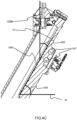
- substantially vertically in this context may mean that the extension of the tubular element 132B is within 10 degrees of the vertical defined by the local gravity direction.
- the vertical is denoted by reference letter V in Fig.4C .
- the upper part 122A of the housing 122A, 122B includes a vertically extending (when the steam generator 120 is orientated for use) chimney portion 141 to which the connector attachment 126 is attachable.
- the chimney portion 141 may assist orientation of the tubular element 132B in the above-described substantially vertical manner.
- the water hose connector 128A is fluidly connected to a water conduit 128B, with the water hose connector 128A and the water conduit 128B forming an elbow 140 at their junction.
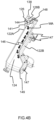
- Figs.4B and 4C show the steam generator 120 when orientated for use.
- the water hose connector 128A extends substantially horizontally, and the water conduit 128B extends substantially vertically. This arrangement of the water inlet 128 may assist to reduce unintended water dosing or dripping into the steam chamber 124.
- substantially vertically in this context may mean that the extension of the water conduit 128B is within 10 degrees of the vertical defined by the local gravity direction.
- the vertical is denoted by reference letter V in Fig.4C .
- substantially horizontally may mean that the extension of the water hose connector 128A is within 10 degrees of the horizontal plane perpendicular to the local gravity direction-defined vertical V.
- the horizontal plane is denoted by reference letter H in Fig.4C .
- the chimney portion 141 may assist orientation of the water conduit 128B in the substantially vertical manner.
- the water inlet aperture 142 is provided in the upper part 122A of the housing 122A, 122B.
- the housing 122A, 122B further delimits a steam outlet aperture 143 adjacent to the water inlet aperture 142.
- the tubular element 132B extends through the steam outlet aperture 143 into the steam chamber 124.
- a portion 145 of the housing 122A, 122B separates the water inlet aperture 142 from the steam outlet aperture 143
- water is delivered and the tubular element 132B extends through a single aperture provided in the housing 122A, 122B.
- the steam generator 120 preferably comprises an anti-scale adhesion conduit 144 fluidly connected to the water conduit 128B of the water inlet 128 (irrespective of whether or not the water inlet 128 includes the water hose connector 128A).
- the anti-scale adhesion conduit 144 protrudes into the steam chamber 124 for supplying water into the steam chamber 124.
- the anti-scale adhesion conduit 144 extends from and/or via the water inlet aperture 142.
- the anti-scale adhesion conduit 144 may assist to minimise or prevent scale obstructing delivery of water into the steam chamber 124.
- the anti-scale adhesion conduit 144 may be formed from a non-stick material, such as a fluoropolymer.
- the anti-scale adhesion conduit 144 is in the form of a tubular insert formed from a fluoropolymer material.
- a fluoropolymer material With its relatively low adhesion to scale, such a fluoropolymer material can assist to reduce scale build-up and promote scale flaking.
- the fluoropolymer material may assist to prevent scale choking water delivery into the steam chamber 124.
- the steam generator 120 comprises a steaming surface 146 arranged to vaporise water thereon to generate the steam.
- the steaming surface 146 is included in the lower part 122B of the housing 122A, 122B.
- the steaming surface 146 is heated via a heating element arrangement 147 arranged in the lower part 122B of the housing 122A, 122B.
- the steaming surface 146 slopes at an oblique angle OA relative to the substantially vertically extending water conduit 128B.
- the term oblique in this context refers to the extension of the steaming surface 146 being neither parallel with nor perpendicular to the direction of extension of the water conduit 128B.
- This arrangement of the steaming surface 146 relative to the water conduit 128B may promote vaporization of water dosed (see the arrows WA in Fig.4B ) onto the steaming surface 146, and thereby assist to minimise accumulation of water at a base 149 of the steam chamber 124.
- the water inlet 128 is preferably positioned as high as possible (considering the in-use orientation of the steam generator 120) to assist with more of the steaming surface 146 being utilised for vaporising the water, and to assist with prolonging the time taken for the water to reach the bottom of the steaming surface 146 (which may be at a lower temperature), so as to minimise water accumulation at the base 149 of the steam chamber 124.
- the steam outlet 132 is preferably positioned as high as possible (considering the in-use orientation of the steam generator 120) and as far as possible from the steaming surface 146. This may assist to extend the operating lifetime of the steam generator 120, since scale may mostly accumulate at the base 149 to mid-region of the steam chamber 124, and generally heavier particles of scale may be more difficult for the steam to carry to a more elevated steam outlet 132.
- the steaming surface 146 slopes at an oblique angle OA in the range [15;45] degrees relative to the substantially vertically extending water conduit 128B.
- the steaming surface 146 may be at an angle AH in a range of [45;75] degrees relative to the horizontal H. This range of angles has been found to be optimal for minimising accumulation of water at the base 149 of the steam chamber 124, even at relatively high water flow rates. Such angles may also permit more efficient flaking and dropping of the scale from the steaming surface 146 to enable scale to accumulate in a scale deposition area at the base 149 of the steam chamber 124. This, in turn, may assist to prolong the instantaneous steam generation capability of the steam generator 120, since less scale adhered to the steaming surface 146 may mean that heat is more efficiently transferred to the water dosed thereon.
- the steam generator 120 comprises a seal member 148 arranged between the connector attachment 126 and the housing 122A, 122B.
- the seal member 148 may assist to minimise or prevent fluid, in particular steam and water, leakage from the steam chamber 124 between the housing 122A, 122B and the connector attachment 126.
- the seal member 148 can be formed of any suitable material.
- the seal member 148 is formed of an elastomeric material, such as silicone rubber.
- the seal member 148 preferably delimits:
- the second hole 152 may permit the anti-scale adhesion conduit 144 to pass through the wall of the housing 122A, 122B and to enter into the steam chamber 124.
- first hole 150 and the second hole 152 are separated from each other by a part 151 of the seal member 148.
- the seal member 148 comprises a surface portion 155 for extending around the anti-scale adhesion conduit 144, and a nose portion 154 arranged to extend, for example being enlarged, substantially perpendicularly to the surface portion 155 at the extremity of the anti-scale adhesion conduit 144.
- a steam chamber-exposed end of the anti-scale adhesion conduit 144 for example the tubular insert, can align with a steam chamber-exposed surface portion of the nose portion 154.
- This end of the anti-scale adhesion conduit 144 being aligned, for example aligned flush, with this surface portion of the nose portion 154 may further promote scale flaking during temperature cycling of the steam generator 120. This may be due to the mismatch in coefficient of thermal expansion between the material, for example elastomeric material, of the seal member 148 and the anti-scale adhesion, for example fluoropolymer, material of the anti-scale adhesion conduit 144.
- the seal member 148 can engage with the housing 122A, 122B in any suitable manner.
- the nose portion 154 is insertable into the steam chamber 124 via the water inlet aperture 142 but is shaped so that, once inserted, withdrawal of the nose portion 154 back through the water inlet aperture 142 is restricted.
- the nose portion 154 is conical, although other shapes which mean that insertion of the nose portion 154 into the steam chamber 124 is more facile than withdrawal of the nose portion 154 therefrom can also be contemplated, such as pyramidal.
- the water inlet 128 comprises a hose retaining portion 156 for assisting retention of the water hose 130.
- the hose retaining portion 156 is included in the above-described water hose connector 128A.
- the hose retaining portion 156 is defined by annular protrusion(s) protruding from an external surface of the water hose connector 128A.
- the water hose 130 can alternatively or additionally be secured to the water hose connector 128A using a water hose clamp 157 arranged to compress the water hose 130 around and against the water hose connector 128A.
- the steam outlet 132 can comprise a further hose retaining portion 158 for assisting retention of the steam hose 134.
- the further hose retaining portion 158 is included in the hose connector 132A.
- the further hose retaining portion 158 is defined by annular protrusion(s) protruding from an external surface of the hose connector 132A.
- the steam hose 134 can alternatively or additionally be secured to the hose connector 132A using a steam hose clamp 159 arranged to compress the steam hose 134 around and against the hose connector 132A.
- the hose retaining portion 156 and/or the further hose retaining portion 158 can be relatively straightforwardly provided, for example via a molding process used to fabricate the connector attachment 126.
- the connector attachment 126 is attachable to the housing 122A, 122B in any suitable manner.
- the connector attachment 126 is attachable to the housing 122A, 122B via screws 160 which pass through holes delimited by the connector attachment 126 and screw into openings delimited by the housing 122A, 122B.
- the connector attachment 126 preferably comprises a plate member 168 arranged to support the water inlet 128 and the steam outlet 132.
- the seal member 148 can contact an underside of the plate member 168 and an outer surface of the housing 122A, 122B.
- the seal member 148 is preferably received in a complementarily shaped recessed portion of the outer surface of the housing 122A, 122B.
- the plate member 168 preferably has one or more alignment features for assisting locating of the connector attachment 126 at the correct position on the housing 122A, 122B and/or on the seal member 148.
- the underside of the plate member 168 can include an annular ridge 174 around the tubular element 132B and/or a further annular ridge 176 around the water conduit 128B compressing the seal member 148 to ensure proper sealing between the plate member 168 and the upper part 122A of the housing 122A, 122B.
- one or more studs 178 protruding from the underside of the plate member 168 can facilitate engagement of the connector attachment 126 with the seal member 148.
- Figs.7A and 7B provide views of an anti-scale adhesion conduit 144 in the form of a tubular insert.
- the anti-scale adhesion conduit 144 comprises a downstream cylindrical portion 180 and an upstream flared portion 182.
- the upstream flared portion 182 may assist to restrict movement of the anti-scale adhesion conduit 144 in the second hole 152 of the seal member 148 in the direction of the steam chamber 124.
- Fig.8 schematically depicts a steam generator testing arrangement.
- the box 184 denotes a supply of water with a pH of 7.5 to 7.9, a hardness [dH] of 11.1 to 14.1, and a conductivity [ ⁇ S] of 670 to 830.
- This water is used to fill a water tank 186.
- a pump 188 is used to pump the water from the water tank 186 to the steam generator 120. Condensed water is collected in the container 190.
- steam may transfer energy to the steam hose 134 and condense to water.
- the quantity of water being collected in the container 190 may correspond to the sum of the steam condensed water and the amount of water droplets which have escaped from the steam generator without being vaporized.
- the benefits provided by the connector attachment 126 may not be associated with compromised steaming performance.
Landscapes
- Engineering & Computer Science (AREA)
- Life Sciences & Earth Sciences (AREA)
- Sustainable Development (AREA)
- Sustainable Energy (AREA)
- Physics & Mathematics (AREA)
- Thermal Sciences (AREA)
- Mechanical Engineering (AREA)
- General Engineering & Computer Science (AREA)
- Health & Medical Sciences (AREA)
- Public Health (AREA)
- Textile Engineering (AREA)
- Devices For Medical Bathing And Washing (AREA)
Priority Applications (5)
| Application Number | Priority Date | Filing Date | Title |
|---|---|---|---|
| EP22175073.0A EP4283190A1 (fr) | 2022-05-24 | 2022-05-24 | Accessoire de connecteur et générateur de vapeur le comprenant |
| CN202380012841.1A CN117651829B (zh) | 2022-05-24 | 2023-05-19 | 连接器附接件和包括其的蒸汽发生器 |
| KR1020247005260A KR102785516B1 (ko) | 2022-05-24 | 2023-05-19 | 커넥터 부착부 및 이를 포함한 스팀 발생기 |
| EP23728681.0A EP4348112A1 (fr) | 2022-05-24 | 2023-05-19 | Fixation de raccord et générateur de vapeur le comprenant |
| PCT/EP2023/063522 WO2023227487A1 (fr) | 2022-05-24 | 2023-05-19 | Fixation de raccord et générateur de vapeur le comprenant |
Applications Claiming Priority (1)
| Application Number | Priority Date | Filing Date | Title |
|---|---|---|---|
| EP22175073.0A EP4283190A1 (fr) | 2022-05-24 | 2022-05-24 | Accessoire de connecteur et générateur de vapeur le comprenant |
Publications (1)
| Publication Number | Publication Date |
|---|---|
| EP4283190A1 true EP4283190A1 (fr) | 2023-11-29 |
Family
ID=81846471
Family Applications (2)
| Application Number | Title | Priority Date | Filing Date |
|---|---|---|---|
| EP22175073.0A Withdrawn EP4283190A1 (fr) | 2022-05-24 | 2022-05-24 | Accessoire de connecteur et générateur de vapeur le comprenant |
| EP23728681.0A Pending EP4348112A1 (fr) | 2022-05-24 | 2023-05-19 | Fixation de raccord et générateur de vapeur le comprenant |
Family Applications After (1)
| Application Number | Title | Priority Date | Filing Date |
|---|---|---|---|
| EP23728681.0A Pending EP4348112A1 (fr) | 2022-05-24 | 2023-05-19 | Fixation de raccord et générateur de vapeur le comprenant |
Country Status (4)
| Country | Link |
|---|---|
| EP (2) | EP4283190A1 (fr) |
| KR (1) | KR102785516B1 (fr) |
| CN (1) | CN117651829B (fr) |
| WO (1) | WO2023227487A1 (fr) |
Citations (7)
| Publication number | Priority date | Publication date | Assignee | Title |
|---|---|---|---|---|
| GB2227821A (en) * | 1989-01-26 | 1990-08-08 | Ward Bekker Sales Limited | Devices for generating steam; wallpaper strippers |
| FR2714401A1 (fr) * | 1993-12-24 | 1995-06-30 | Seb Sa | Dispositif de distribution de vapeur. |
| US20050034487A1 (en) * | 2003-08-13 | 2005-02-17 | Soo-Young Oh | Drum type washing machine and vapor generator thereof |
| DE202009001043U1 (de) * | 2008-09-26 | 2009-05-07 | Zhejiang Huaguang Electrical Appliance Group Co., Ltd., Cixi City | Dampferzeuger |
| EP2467526A1 (fr) * | 2009-08-17 | 2012-06-27 | BSH Bosch und Siemens Hausgeräte GmbH | Générateur de vapeur s'utilisant dans un appareil de blanchisserie, et appareil de blanchisserie |
| US20170268162A1 (en) * | 2014-08-26 | 2017-09-21 | Koninklijke Philips N.V. | Steam iron head |
| EP3406790A1 (fr) * | 2017-05-22 | 2018-11-28 | POLTI S.p.A. | Chaudière pour générer de la vapeur et appareils électroménagers contenant ladite chaudière |
Family Cites Families (8)
| Publication number | Priority date | Publication date | Assignee | Title |
|---|---|---|---|---|
| AU2003255958A1 (en) * | 2002-08-26 | 2004-03-11 | Koninklijke Philips Electronics N.V. | Electric steaming device |
| GB201017461D0 (en) * | 2010-10-15 | 2010-12-01 | Strix Ltd | Electric steam generation |
| KR20140064862A (ko) * | 2011-08-16 | 2014-05-28 | 우드 스톤 아이디어즈, 엘엘시 | 증기발생 시스템 |
| DE202014011498U1 (de) * | 2013-07-25 | 2021-06-09 | Koninklijke Philips N.V. | Einrichtung zum Erzeugen von Dampf |
| CN105518209B (zh) * | 2013-09-06 | 2018-12-14 | 皇家飞利浦有限公司 | 具有过滤器单元的蒸汽处理器、过滤器芯和输送蒸汽的方法 |
| TR201908929T4 (tr) * | 2014-08-26 | 2019-07-22 | Koninklijke Philips Nv | Bir buharlama cihazı için bir buhar jeneratörü. |
| TR201910982T4 (tr) * | 2015-11-17 | 2019-08-21 | Koninklijke Philips Nv | Kazantaşı pullarını toplamak için bir kap içeren buhar oluşturmak için cihaz ve yöntem. |
| EP3771769A1 (fr) * | 2019-07-30 | 2021-02-03 | Koninklijke Philips N.V. | Générateur de vapeur comportant une chambre de vapeur et un trou de dosage disposés à proximité d'une partie arrière de la chambre de vapeur |
-
2022
- 2022-05-24 EP EP22175073.0A patent/EP4283190A1/fr not_active Withdrawn
-
2023
- 2023-05-19 WO PCT/EP2023/063522 patent/WO2023227487A1/fr not_active Ceased
- 2023-05-19 KR KR1020247005260A patent/KR102785516B1/ko active Active
- 2023-05-19 EP EP23728681.0A patent/EP4348112A1/fr active Pending
- 2023-05-19 CN CN202380012841.1A patent/CN117651829B/zh active Active
Patent Citations (7)
| Publication number | Priority date | Publication date | Assignee | Title |
|---|---|---|---|---|
| GB2227821A (en) * | 1989-01-26 | 1990-08-08 | Ward Bekker Sales Limited | Devices for generating steam; wallpaper strippers |
| FR2714401A1 (fr) * | 1993-12-24 | 1995-06-30 | Seb Sa | Dispositif de distribution de vapeur. |
| US20050034487A1 (en) * | 2003-08-13 | 2005-02-17 | Soo-Young Oh | Drum type washing machine and vapor generator thereof |
| DE202009001043U1 (de) * | 2008-09-26 | 2009-05-07 | Zhejiang Huaguang Electrical Appliance Group Co., Ltd., Cixi City | Dampferzeuger |
| EP2467526A1 (fr) * | 2009-08-17 | 2012-06-27 | BSH Bosch und Siemens Hausgeräte GmbH | Générateur de vapeur s'utilisant dans un appareil de blanchisserie, et appareil de blanchisserie |
| US20170268162A1 (en) * | 2014-08-26 | 2017-09-21 | Koninklijke Philips N.V. | Steam iron head |
| EP3406790A1 (fr) * | 2017-05-22 | 2018-11-28 | POLTI S.p.A. | Chaudière pour générer de la vapeur et appareils électroménagers contenant ladite chaudière |
Also Published As
| Publication number | Publication date |
|---|---|
| CN117651829B (zh) | 2025-08-15 |
| KR20240028541A (ko) | 2024-03-05 |
| WO2023227487A1 (fr) | 2023-11-30 |
| EP4348112A1 (fr) | 2024-04-10 |
| KR102785516B1 (ko) | 2025-03-21 |
| CN117651829A (zh) | 2024-03-05 |
Similar Documents
| Publication | Publication Date | Title |
|---|---|---|
| US6427365B2 (en) | Fluid supply and reservoir for a clothes refreshing appliance | |
| CN107429475B (zh) | 具有水垢收集室的手持式蒸汽挂烫机 | |
| CN109629213B (zh) | 安装有配备有清洁口的蒸发室的熨平设备 | |
| WO2022161256A1 (fr) | Ensemble noyau d'atomisation, atomiseur et dispositif d'atomisation électronique | |
| CN114794547B (zh) | 雾化器和电子雾化装置 | |
| EP4283190A1 (fr) | Accessoire de connecteur et générateur de vapeur le comprenant | |
| JP2022524313A (ja) | 蒸気供給システム用のアトマイザエンクロージャ | |
| CN112931972A (zh) | 雾化芯的内底部设有雾化腔的雾化器 | |
| WO2022161257A1 (fr) | Ensemble noyau d'atomisation, atomiseur et dispositif d'atomisation électronique | |
| CN114729498B (zh) | 用于蒸汽熨烫设备的板及相应的制造方法 | |
| WO2023143066A1 (fr) | Appareil de génération d'aérosol | |
| KR100641843B1 (ko) | 물 유출 방지 환수구조를 갖는 스팀청소기 | |
| CN115590249A (zh) | 雾化器及气溶胶生成装置 | |
| US20240200790A1 (en) | Cooking oven | |
| US7543526B1 (en) | Coffee maker | |
| CN212787424U (zh) | 气溶胶发生装置 | |
| CN207785105U (zh) | 洗碗机 | |
| CN215906425U (zh) | 衣物处理装置及其前支撑组件 | |
| KR101012978B1 (ko) | 청소기의 노즐 | |
| CN222773272U (zh) | 蒸汽发生装置及熨烫器 | |
| CN222055187U (zh) | 蒸汽烹饪装置 | |
| CN220192166U (zh) | 一种雾化器及电子雾化装置 | |
| WO2025026242A1 (fr) | Appareil d'atomisation et dispositif d'atomisation | |
| CN217082496U (zh) | 蒸汽发热锅以及挂烫机 | |
| EP4051027A1 (fr) | Plaques chauffantes |
Legal Events
| Date | Code | Title | Description |
|---|---|---|---|
| PUAI | Public reference made under article 153(3) epc to a published international application that has entered the european phase |
Free format text: ORIGINAL CODE: 0009012 |
|
| STAA | Information on the status of an ep patent application or granted ep patent |
Free format text: STATUS: THE APPLICATION HAS BEEN PUBLISHED |
|
| AK | Designated contracting states |
Kind code of ref document: A1 Designated state(s): AL AT BE BG CH CY CZ DE DK EE ES FI FR GB GR HR HU IE IS IT LI LT LU LV MC MK MT NL NO PL PT RO RS SE SI SK SM TR |
|
| STAA | Information on the status of an ep patent application or granted ep patent |
Free format text: STATUS: THE APPLICATION IS DEEMED TO BE WITHDRAWN |
|
| 18D | Application deemed to be withdrawn |
Effective date: 20240530 |