EP4283197A2 - Brennkammer - Google Patents
Brennkammer Download PDFInfo
- Publication number
- EP4283197A2 EP4283197A2 EP23203379.5A EP23203379A EP4283197A2 EP 4283197 A2 EP4283197 A2 EP 4283197A2 EP 23203379 A EP23203379 A EP 23203379A EP 4283197 A2 EP4283197 A2 EP 4283197A2
- Authority
- EP
- European Patent Office
- Prior art keywords
- fluid
- inner tube
- passage
- tube
- fuel
- Prior art date
- Legal status (The legal status is an assumption and is not a legal conclusion. Google has not performed a legal analysis and makes no representation as to the accuracy of the status listed.)
- Granted
Links
Images







Classifications
-
- F—MECHANICAL ENGINEERING; LIGHTING; HEATING; WEAPONS; BLASTING
- F23—COMBUSTION APPARATUS; COMBUSTION PROCESSES
- F23R—GENERATING COMBUSTION PRODUCTS OF HIGH PRESSURE OR HIGH VELOCITY, e.g. GAS-TURBINE COMBUSTION CHAMBERS
- F23R3/00—Continuous combustion chambers using liquid or gaseous fuel
- F23R3/42—Continuous combustion chambers using liquid or gaseous fuel characterised by the arrangement or form of the flame tubes or combustion chambers
- F23R3/58—Cyclone or vortex type combustion chambers
-
- F—MECHANICAL ENGINEERING; LIGHTING; HEATING; WEAPONS; BLASTING
- F23—COMBUSTION APPARATUS; COMBUSTION PROCESSES
- F23R—GENERATING COMBUSTION PRODUCTS OF HIGH PRESSURE OR HIGH VELOCITY, e.g. GAS-TURBINE COMBUSTION CHAMBERS
- F23R3/00—Continuous combustion chambers using liquid or gaseous fuel
-
- F—MECHANICAL ENGINEERING; LIGHTING; HEATING; WEAPONS; BLASTING
- F23—COMBUSTION APPARATUS; COMBUSTION PROCESSES
- F23R—GENERATING COMBUSTION PRODUCTS OF HIGH PRESSURE OR HIGH VELOCITY, e.g. GAS-TURBINE COMBUSTION CHAMBERS
- F23R3/00—Continuous combustion chambers using liquid or gaseous fuel
- F23R3/02—Continuous combustion chambers using liquid or gaseous fuel characterised by the air-flow or gas-flow configuration
- F23R3/04—Air inlet arrangements
- F23R3/06—Arrangement of apertures along the flame tube
-
- F—MECHANICAL ENGINEERING; LIGHTING; HEATING; WEAPONS; BLASTING
- F23—COMBUSTION APPARATUS; COMBUSTION PROCESSES
- F23R—GENERATING COMBUSTION PRODUCTS OF HIGH PRESSURE OR HIGH VELOCITY, e.g. GAS-TURBINE COMBUSTION CHAMBERS
- F23R3/00—Continuous combustion chambers using liquid or gaseous fuel
- F23R3/28—Continuous combustion chambers using liquid or gaseous fuel characterised by the fuel supply
-
- F—MECHANICAL ENGINEERING; LIGHTING; HEATING; WEAPONS; BLASTING
- F23—COMBUSTION APPARATUS; COMBUSTION PROCESSES
- F23R—GENERATING COMBUSTION PRODUCTS OF HIGH PRESSURE OR HIGH VELOCITY, e.g. GAS-TURBINE COMBUSTION CHAMBERS
- F23R3/00—Continuous combustion chambers using liquid or gaseous fuel
- F23R3/28—Continuous combustion chambers using liquid or gaseous fuel characterised by the fuel supply
- F23R3/286—Continuous combustion chambers using liquid or gaseous fuel characterised by the fuel supply having fuel-air premixing devices
-
- F—MECHANICAL ENGINEERING; LIGHTING; HEATING; WEAPONS; BLASTING
- F23—COMBUSTION APPARATUS; COMBUSTION PROCESSES
- F23R—GENERATING COMBUSTION PRODUCTS OF HIGH PRESSURE OR HIGH VELOCITY, e.g. GAS-TURBINE COMBUSTION CHAMBERS
- F23R3/00—Continuous combustion chambers using liquid or gaseous fuel
- F23R3/42—Continuous combustion chambers using liquid or gaseous fuel characterised by the arrangement or form of the flame tubes or combustion chambers
- F23R3/46—Combustion chambers comprising an annular arrangement of several essentially tubular flame tubes within a common annular casing or within individual casings
-
- Y—GENERAL TAGGING OF NEW TECHNOLOGICAL DEVELOPMENTS; GENERAL TAGGING OF CROSS-SECTIONAL TECHNOLOGIES SPANNING OVER SEVERAL SECTIONS OF THE IPC; TECHNICAL SUBJECTS COVERED BY FORMER USPC CROSS-REFERENCE ART COLLECTIONS [XRACs] AND DIGESTS
- Y02—TECHNOLOGIES OR APPLICATIONS FOR MITIGATION OR ADAPTATION AGAINST CLIMATE CHANGE
- Y02T—CLIMATE CHANGE MITIGATION TECHNOLOGIES RELATED TO TRANSPORTATION
- Y02T50/00—Aeronautics or air transport
- Y02T50/60—Efficient propulsion technologies, e.g. for aircraft
Definitions
- the invention relates to a fuel burner and, in particular, relates to a combustor for a heating appliance, gas turbine engine or jet engine that imparts a centrifugal force upon combustion air or a combination of air and fuel.
- a combustor for a heating appliance, gas turbine engine or jet engine that imparts a centrifugal force upon combustion air or a combination of air and fuel.
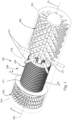
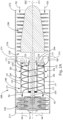
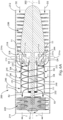
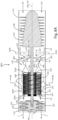
- the combustor 240 includes outer and inner tubes 242, 244 that are concentric to one another about a central axis 241 and secured to one another and the housing 210.
- the central axis 241 of the combustor 240 can be coaxial with the axis 202 of the engine 202 or can be spaced from the axis of the engine (not shown).
- the connecting member 232 extends through the inner tube 244 and a shaft seal 233 is provided between the connecting member and the inner tube to prevent fluid from passing between the connecting member and the inner tube directly into the turbine 220.
- the space between the outer and inner tubes 242, 244 defines a fluid passage 274 for receiving fuel and air.
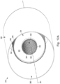
- the periphery of the outer tube 242 includes fluid directing structure 248 for directing fluid radially inward to the fluid passage 274. More specifically, the fluid directing structure 248 is configured to direct fluid to the fluid passage 274 in a direction that is offset from the central axis 241 of the combustor 240 and along a path that is angled relative to the normal of the inner surface (not shown) of the outer tube 242.
- the periphery of the inner tube 244 includes fluid directing structure 252 for directing fluid from the interior 250 of the inner tube radially outward into the fluid passage 274. More specifically, the fluid directing structure 252 is configured to direct fluid into the fluid passage 274 in a direction that is offset from the central axis 241 of the combustor 240 and along a path that is angled relative to the normal of the outer surface (not shown) of the inner tube 244.
- the fluid directing structures 248, 252 can direct their respective fluid in the same general direction.
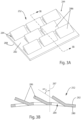
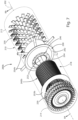
- the fluid directing structure 248, 252 can include a series of openings with associated fins or guides for directing the fluid in the desired manner ( Figs. 3A-4D ).
- a ring-shaped wall 251 ( see Fig. 2B ) is secured to the end of the outer and inner tubes 242, 244 closer to the compressor 230 in order to seal one end of the fluid passage 274 in a fluid-tight manner.
- the wall 251 is provided with openings 253 that receive ends of the fuel supply members 254 to establish the direct fluid path between the fuel supply members and the fluid passage 274.
- the compressed air D4 is imparted with a centrifugal force about the central axis 241 of the combustor 240 as it enters the fluid passage 274.
- the swirling air D4 mixes with the fuel F1 to create a swirling air/fuel mixture within the fluid passage 274 and about the central axis 241 of the combustor 240.
- One or more endless loops of openings 284 can be positioned adjacent to one another or spaced from one another along the length of the inner tube 244. Each loop can have any number of openings 284.
- the openings 284 in adjacent loops can be aligned with one another or can be offset from one another.
- the size, shape, configuration, and alignment of the openings 284 in the inner tube 244 is dictated by desired flow and performance characteristics of the compressed air D3 flowing through the openings.
- the openings 284 are illustrated as being arranged in a predetermined pattern along the inner tube 244, it will be appreciated that the openings can be randomly positioned along the inner tube (not shown).
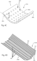
- Figs. 4A-D illustrate alternative configurations of the fluid directing structure 252, 248 that can be formed on or integrally attached to the inner and/or outer surface of the respective tube 244, 242 in accordance with the present invention. More specifically, either of the fluid directing structures 248, 252 can exhibit any of the configurations shown in Figs. 4A-D .
- the fluid directing structure 252c includes a plurality of openings 284c that extend from the inner surface 282c of the inner tube 244c to the outer surface 280c.
- the openings 284c extend through the inner tube 244c at an angle relative to the axis 287c extending normal to the outer surface 280c of the inner tube 244c and through the central axis 241 of the combustor 240.
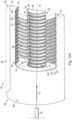
- Figs. 9-11 illustrate a jet engine 200c in accordance with another aspect of the present invention.
- a plurality of combustors 240c is arranged about the central axis 202 of the jet engine.
- Each of the combustors 240c can constitute the non-pre-mixed combustor 240 of Figs. 1-2B , the partially pre-mixed combustor 240a of Figs. 5 -6B or the fully pre-mixed combustor 240b of Figs. 7-8 or modifications thereof.
- Features in Figs. 9-11 that are identical to features in Figs. 1-8 have the same reference number as Figs. 1-8 , whereas features in Figs. 9-11 that are similar to features in Figs. 1-8 are given the suffix "c".
- an igniter within the interior 274' of the tube member 242' of each combustor 240c ignites the swirling air/fuel mixtures.
- the swirling combustion products collectively exit the combustors 240c and pass through the turbine 220, causing rotation of the turbine and expulsion of the combustion products from the jet engine 200c.
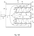
- the pre-mixed portion F7 flows to the radial space between the housing 380 and the outer tube 342.
- the fluid directing structure 348 directs the pre-mixed portion F7 radially inward into the fluid passage 374.
- the end wall 390 prevents the pre-mixed portion F7 from exiting the second end 384 of the housing 380 except through the fluid directing structure 348. Due to the configuration of the fluid directing structure 348, the pre-mixed portion F7 is imparted with a centrifugal force about the axis 341 of the combustor 340 as it passes radially inward into the fluid passage 374.
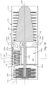
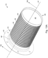
- Figs. 13A-13B illustrate a combustor or fuel burner 410 in accordance with another aspect of the present invention.
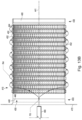
- the combustor 410 constitutes an external swirl burner that can be used in industrial, household, and commercial heating appliances such as, for example, a water heater, boiler, furnace, etc. More specifically, the combustor 410 produces a swirling, spiraling and/or rotating flame about and along its exterior in a simple, inexpensive, and efficient manner.
- the combustor 410 includes a tube 444 extending along a central axis 441 from a first end 433 to a second end 435.
- the tube 444 includes an inner surface 446 defining an interior or central passage 450 and an outer surface 448.
- the first end 433 of the tube 444 includes a flange 470 for securing the combustor 410 to, for example, a portion of the appliance.
- a wall 460 is secured to the second end 435 of the tube 444 to seal one end of the central passage 450 in a fluid-tight manner.
- the combustor 410 does not include an outer tube or housing and, thus, the tube 444 defines both the exterior and interior of the combustor 410.
Landscapes
- Engineering & Computer Science (AREA)
- Chemical & Material Sciences (AREA)
- Combustion & Propulsion (AREA)
- Mechanical Engineering (AREA)
- General Engineering & Computer Science (AREA)
- Gas Burners (AREA)
- Pre-Mixing And Non-Premixing Gas Burner (AREA)
Applications Claiming Priority (3)
| Application Number | Priority Date | Filing Date | Title |
|---|---|---|---|
| US15/358,221 US10634354B2 (en) | 2011-08-11 | 2016-11-22 | Combustor |
| PCT/US2017/062800 WO2018098157A2 (en) | 2016-11-22 | 2017-11-21 | Combustor |
| EP17874218.5A EP3545236B1 (de) | 2016-11-22 | 2017-11-21 | Brennkammer |
Related Parent Applications (2)
| Application Number | Title | Priority Date | Filing Date |
|---|---|---|---|
| EP17874218.5A Division EP3545236B1 (de) | 2016-11-22 | 2017-11-21 | Brennkammer |
| EP17874218.5A Division-Into EP3545236B1 (de) | 2016-11-22 | 2017-11-21 | Brennkammer |
Publications (3)
| Publication Number | Publication Date |
|---|---|
| EP4283197A2 true EP4283197A2 (de) | 2023-11-29 |
| EP4283197A3 EP4283197A3 (de) | 2024-02-14 |
| EP4283197B1 EP4283197B1 (de) | 2025-07-16 |
Family
ID=62195627
Family Applications (2)
| Application Number | Title | Priority Date | Filing Date |
|---|---|---|---|
| EP17874218.5A Active EP3545236B1 (de) | 2016-11-22 | 2017-11-21 | Brennkammer |
| EP23203379.5A Active EP4283197B1 (de) | 2016-11-22 | 2017-11-21 | Brennkammer |
Family Applications Before (1)
| Application Number | Title | Priority Date | Filing Date |
|---|---|---|---|
| EP17874218.5A Active EP3545236B1 (de) | 2016-11-22 | 2017-11-21 | Brennkammer |
Country Status (4)
| Country | Link |
|---|---|
| EP (2) | EP3545236B1 (de) |
| CN (1) | CN110741205B (de) |
| CA (1) | CA3044567A1 (de) |
| WO (1) | WO2018098157A2 (de) |
Families Citing this family (1)
| Publication number | Priority date | Publication date | Assignee | Title |
|---|---|---|---|---|
| CN119468251B (zh) * | 2024-12-04 | 2025-09-05 | 中国航发沈阳发动机研究所 | 一种双折流预混预蒸发式火焰稳定器 |
Family Cites Families (15)
| Publication number | Priority date | Publication date | Assignee | Title |
|---|---|---|---|---|
| US2718757A (en) * | 1951-01-17 | 1955-09-27 | Lummus Co | Aircraft gas turbine and jet |
| US2837893A (en) * | 1952-12-12 | 1958-06-10 | Phillips Petroleum Co | Automatic primary and secondary air flow regulation for gas turbine combustion chamber |
| US2993337A (en) * | 1959-02-12 | 1961-07-25 | Herbert L Cheeseman | Turbine combustor |
| US4162140A (en) * | 1977-09-26 | 1979-07-24 | John Zink Company | NOx abatement in burning of gaseous or liquid fuels |
| US4519770A (en) * | 1980-06-30 | 1985-05-28 | Alzeta Corp. | Firetube boiler heater system |
| US5240411A (en) * | 1992-02-10 | 1993-08-31 | Mor-Flo Industries, Inc. | Atmospheric gas burner assembly |
| US5888059A (en) * | 1992-10-01 | 1999-03-30 | Expro North Sea Limited | Combustion apparatus |
| US6623267B1 (en) * | 2002-12-31 | 2003-09-23 | Tibbs M. Golladay, Jr. | Industrial burner |
| JP4476176B2 (ja) * | 2005-06-06 | 2010-06-09 | 三菱重工業株式会社 | ガスタービンの予混合燃焼バーナー |
| US8166763B2 (en) * | 2006-09-14 | 2012-05-01 | Solar Turbines Inc. | Gas turbine fuel injector with a removable pilot assembly |
| CA2844693A1 (en) * | 2011-08-11 | 2013-02-14 | Beckett Gas, Inc. | Combustor |
| US9528698B2 (en) * | 2011-08-11 | 2016-12-27 | Richard D. Cook | Burner |
| US20130219899A1 (en) * | 2012-02-27 | 2013-08-29 | General Electric Company | Annular premixed pilot in fuel nozzle |
| US9759425B2 (en) * | 2013-03-12 | 2017-09-12 | General Electric Company | System and method having multi-tube fuel nozzle with multiple fuel injectors |
| US20150226421A1 (en) * | 2014-02-12 | 2015-08-13 | Breen Energy Solutions | Method of Co-Firing Coal or Oil with a Gaseous Fuel in a Furnace |
-
2017
- 2017-11-21 EP EP17874218.5A patent/EP3545236B1/de active Active
- 2017-11-21 EP EP23203379.5A patent/EP4283197B1/de active Active
- 2017-11-21 CN CN201780084249.7A patent/CN110741205B/zh not_active Expired - Fee Related
- 2017-11-21 WO PCT/US2017/062800 patent/WO2018098157A2/en not_active Ceased
- 2017-11-21 CA CA3044567A patent/CA3044567A1/en active Pending
Also Published As
| Publication number | Publication date |
|---|---|
| CA3044567A1 (en) | 2018-05-31 |
| EP4283197A3 (de) | 2024-02-14 |
| EP3545236A4 (de) | 2021-08-18 |
| EP3545236B1 (de) | 2024-01-24 |
| CN110741205A (zh) | 2020-01-31 |
| CN110741205B (zh) | 2021-01-26 |
| EP3545236A2 (de) | 2019-10-02 |
| WO2018098157A2 (en) | 2018-05-31 |
| WO2018098157A3 (en) | 2020-07-09 |
| EP4283197B1 (de) | 2025-07-16 |
Similar Documents
| Publication | Publication Date | Title |
|---|---|---|
| US20140190178A1 (en) | Combustor | |
| US7581396B2 (en) | Mixer assembly for combustor of a gas turbine engine having a plurality of counter-rotating swirlers | |
| CN1467407B (zh) | 带有截留涡流空腔的气体涡轮发动机燃烧室筒 | |
| CN103850796B (zh) | 燃气涡轮发动机系统及其相关方法 | |
| CN103822228B (zh) | 燃料喷嘴及其组装方法 | |
| EP2383516A2 (de) | Gelöcherter Luft- und Brennstoffmischschlauch | |
| US8015814B2 (en) | Turbine engine having folded annular jet combustor | |
| JP4997018B2 (ja) | 一次燃料噴射器及び複数の二次燃料噴射ポートを有するガスタービンエンジン燃焼器のミキサ組立体のためのパイロットミキサ | |
| US11708973B2 (en) | Combustor | |
| JP2008190855A (ja) | ガスタービンエンジン燃焼器のミキサアセンブリ用センターボディ | |
| CN101514819A (zh) | 气冷旋流式喷嘴头 | |
| EP3102877B1 (de) | Verbrennungsanlage | |
| CN107525096B (zh) | 多管延迟贫喷射器 | |
| EP3418638B1 (de) | Brennkammer mit wärmetauscher | |
| JP6595010B2 (ja) | 予混合保炎器を有する燃料ノズルアセンブリ | |
| EP3169938A1 (de) | Axial gestufte gasturbinenbrennkammer mit zwischenstufigem vormischer | |
| EP4283197B1 (de) | Brennkammer | |
| KR20200004455A (ko) | 연료 노즐, 이를 포함하는 연소기 및 가스 터빈 | |
| CA2626259C (en) | Gas turbine engine mixing duct and method to start the engine | |
| JP3888229B2 (ja) | 旋回型低NOx燃焼器 | |
| CN120194331B (zh) | 具有带燃料喷嘴组件的燃烧区段的涡轮发动机 | |
| WO2008059045A1 (en) | Improvements in or relating to combustion apparatus |
Legal Events
| Date | Code | Title | Description |
|---|---|---|---|
| PUAI | Public reference made under article 153(3) epc to a published international application that has entered the european phase |
Free format text: ORIGINAL CODE: 0009012 |
|
| STAA | Information on the status of an ep patent application or granted ep patent |
Free format text: STATUS: THE APPLICATION HAS BEEN PUBLISHED |
|
| AC | Divisional application: reference to earlier application |
Ref document number: 3545236 Country of ref document: EP Kind code of ref document: P |
|
| AK | Designated contracting states |
Kind code of ref document: A2 Designated state(s): AL AT BE BG CH CY CZ DE DK EE ES FI FR GB GR HR HU IE IS IT LI LT LU LV MC MK MT NL NO PL PT RO RS SE SI SK SM TR |
|
| REG | Reference to a national code |
Ref country code: DE Ref legal event code: R079 Ipc: F23R0003280000 Ref country code: DE Ref legal event code: R079 Ref document number: 602017090711 Country of ref document: DE Free format text: PREVIOUS MAIN CLASS: F23R0003000000 Ipc: F23R0003280000 |
|
| PUAL | Search report despatched |
Free format text: ORIGINAL CODE: 0009013 |
|
| AK | Designated contracting states |
Kind code of ref document: A3 Designated state(s): AL AT BE BG CH CY CZ DE DK EE ES FI FR GB GR HR HU IE IS IT LI LT LU LV MC MK MT NL NO PL PT RO RS SE SI SK SM TR |
|
| RIC1 | Information provided on ipc code assigned before grant |
Ipc: F23R 3/58 20060101ALI20240111BHEP Ipc: F23R 3/46 20060101ALI20240111BHEP Ipc: F23R 3/06 20060101ALI20240111BHEP Ipc: F23R 3/00 20060101ALI20240111BHEP Ipc: F23R 3/28 20060101AFI20240111BHEP |
|
| STAA | Information on the status of an ep patent application or granted ep patent |
Free format text: STATUS: REQUEST FOR EXAMINATION WAS MADE |
|
| 17P | Request for examination filed |
Effective date: 20240618 |
|
| RBV | Designated contracting states (corrected) |
Designated state(s): AL AT BE BG CH CY CZ DE DK EE ES FI FR GB GR HR HU IE IS IT LI LT LU LV MC MK MT NL NO PL PT RO RS SE SI SK SM TR |
|
| STAA | Information on the status of an ep patent application or granted ep patent |
Free format text: STATUS: EXAMINATION IS IN PROGRESS |
|
| 17Q | First examination report despatched |
Effective date: 20240906 |
|
| GRAP | Despatch of communication of intention to grant a patent |
Free format text: ORIGINAL CODE: EPIDOSNIGR1 |
|
| STAA | Information on the status of an ep patent application or granted ep patent |
Free format text: STATUS: GRANT OF PATENT IS INTENDED |
|
| INTG | Intention to grant announced |
Effective date: 20250305 |
|
| GRAS | Grant fee paid |
Free format text: ORIGINAL CODE: EPIDOSNIGR3 |
|
| GRAA | (expected) grant |
Free format text: ORIGINAL CODE: 0009210 |
|
| STAA | Information on the status of an ep patent application or granted ep patent |
Free format text: STATUS: THE PATENT HAS BEEN GRANTED |
|
| AC | Divisional application: reference to earlier application |
Ref document number: 3545236 Country of ref document: EP Kind code of ref document: P |
|
| AK | Designated contracting states |
Kind code of ref document: B1 Designated state(s): AL AT BE BG CH CY CZ DE DK EE ES FI FR GB GR HR HU IE IS IT LI LT LU LV MC MK MT NL NO PL PT RO RS SE SI SK SM TR |
|
| REG | Reference to a national code |
Ref country code: GB Ref legal event code: FG4D |
|
| REG | Reference to a national code |
Ref country code: CH Ref legal event code: EP |
|
| REG | Reference to a national code |
Ref country code: DE Ref legal event code: R096 Ref document number: 602017090711 Country of ref document: DE |
|
| REG | Reference to a national code |
Ref country code: NL Ref legal event code: FP Ref country code: IE Ref legal event code: FG4D |
|
| PG25 | Lapsed in a contracting state [announced via postgrant information from national office to epo] |
Ref country code: PT Free format text: LAPSE BECAUSE OF FAILURE TO SUBMIT A TRANSLATION OF THE DESCRIPTION OR TO PAY THE FEE WITHIN THE PRESCRIBED TIME-LIMIT Effective date: 20251117 |
|
| PGFP | Annual fee paid to national office [announced via postgrant information from national office to epo] |
Ref country code: NL Payment date: 20251126 Year of fee payment: 9 |
|
| REG | Reference to a national code |
Ref country code: AT Ref legal event code: MK05 Ref document number: 1814326 Country of ref document: AT Kind code of ref document: T Effective date: 20250716 |
|
| PG25 | Lapsed in a contracting state [announced via postgrant information from national office to epo] |
Ref country code: IS Free format text: LAPSE BECAUSE OF FAILURE TO SUBMIT A TRANSLATION OF THE DESCRIPTION OR TO PAY THE FEE WITHIN THE PRESCRIBED TIME-LIMIT Effective date: 20251116 |
|
| PGFP | Annual fee paid to national office [announced via postgrant information from national office to epo] |
Ref country code: DE Payment date: 20251128 Year of fee payment: 9 |
|
| PG25 | Lapsed in a contracting state [announced via postgrant information from national office to epo] |
Ref country code: NO Free format text: LAPSE BECAUSE OF FAILURE TO SUBMIT A TRANSLATION OF THE DESCRIPTION OR TO PAY THE FEE WITHIN THE PRESCRIBED TIME-LIMIT Effective date: 20251016 |
|
| REG | Reference to a national code |
Ref country code: LT Ref legal event code: MG9D |
|
| PG25 | Lapsed in a contracting state [announced via postgrant information from national office to epo] |
Ref country code: AT Free format text: LAPSE BECAUSE OF FAILURE TO SUBMIT A TRANSLATION OF THE DESCRIPTION OR TO PAY THE FEE WITHIN THE PRESCRIBED TIME-LIMIT Effective date: 20250716 |
|
| PG25 | Lapsed in a contracting state [announced via postgrant information from national office to epo] |
Ref country code: FI Free format text: LAPSE BECAUSE OF FAILURE TO SUBMIT A TRANSLATION OF THE DESCRIPTION OR TO PAY THE FEE WITHIN THE PRESCRIBED TIME-LIMIT Effective date: 20250716 |
|
| PGFP | Annual fee paid to national office [announced via postgrant information from national office to epo] |
Ref country code: IT Payment date: 20251119 Year of fee payment: 9 |
|
| PG25 | Lapsed in a contracting state [announced via postgrant information from national office to epo] |
Ref country code: HR Free format text: LAPSE BECAUSE OF FAILURE TO SUBMIT A TRANSLATION OF THE DESCRIPTION OR TO PAY THE FEE WITHIN THE PRESCRIBED TIME-LIMIT Effective date: 20250716 |
|
| PG25 | Lapsed in a contracting state [announced via postgrant information from national office to epo] |
Ref country code: GR Free format text: LAPSE BECAUSE OF FAILURE TO SUBMIT A TRANSLATION OF THE DESCRIPTION OR TO PAY THE FEE WITHIN THE PRESCRIBED TIME-LIMIT Effective date: 20251017 |
|
| PGFP | Annual fee paid to national office [announced via postgrant information from national office to epo] |
Ref country code: TR Payment date: 20251104 Year of fee payment: 9 |
|
| PG25 | Lapsed in a contracting state [announced via postgrant information from national office to epo] |
Ref country code: SE Free format text: LAPSE BECAUSE OF FAILURE TO SUBMIT A TRANSLATION OF THE DESCRIPTION OR TO PAY THE FEE WITHIN THE PRESCRIBED TIME-LIMIT Effective date: 20250716 |
|
| PG25 | Lapsed in a contracting state [announced via postgrant information from national office to epo] |
Ref country code: LV Free format text: LAPSE BECAUSE OF FAILURE TO SUBMIT A TRANSLATION OF THE DESCRIPTION OR TO PAY THE FEE WITHIN THE PRESCRIBED TIME-LIMIT Effective date: 20250716 |
|
| PG25 | Lapsed in a contracting state [announced via postgrant information from national office to epo] |
Ref country code: PL Free format text: LAPSE BECAUSE OF FAILURE TO SUBMIT A TRANSLATION OF THE DESCRIPTION OR TO PAY THE FEE WITHIN THE PRESCRIBED TIME-LIMIT Effective date: 20250716 Ref country code: BG Free format text: LAPSE BECAUSE OF FAILURE TO SUBMIT A TRANSLATION OF THE DESCRIPTION OR TO PAY THE FEE WITHIN THE PRESCRIBED TIME-LIMIT Effective date: 20250716 |
|
| PG25 | Lapsed in a contracting state [announced via postgrant information from national office to epo] |
Ref country code: RS Free format text: LAPSE BECAUSE OF FAILURE TO SUBMIT A TRANSLATION OF THE DESCRIPTION OR TO PAY THE FEE WITHIN THE PRESCRIBED TIME-LIMIT Effective date: 20251016 |
|
| PG25 | Lapsed in a contracting state [announced via postgrant information from national office to epo] |
Ref country code: ES Free format text: LAPSE BECAUSE OF FAILURE TO SUBMIT A TRANSLATION OF THE DESCRIPTION OR TO PAY THE FEE WITHIN THE PRESCRIBED TIME-LIMIT Effective date: 20250716 |
|
| PG25 | Lapsed in a contracting state [announced via postgrant information from national office to epo] |
Ref country code: RO Free format text: LAPSE BECAUSE OF FAILURE TO SUBMIT A TRANSLATION OF THE DESCRIPTION OR TO PAY THE FEE WITHIN THE PRESCRIBED TIME-LIMIT Effective date: 20250716 |
|
| PG25 | Lapsed in a contracting state [announced via postgrant information from national office to epo] |
Ref country code: SM Free format text: LAPSE BECAUSE OF FAILURE TO SUBMIT A TRANSLATION OF THE DESCRIPTION OR TO PAY THE FEE WITHIN THE PRESCRIBED TIME-LIMIT Effective date: 20250716 |
|
| PG25 | Lapsed in a contracting state [announced via postgrant information from national office to epo] |
Ref country code: DK Free format text: LAPSE BECAUSE OF FAILURE TO SUBMIT A TRANSLATION OF THE DESCRIPTION OR TO PAY THE FEE WITHIN THE PRESCRIBED TIME-LIMIT Effective date: 20250716 |
|
| PG25 | Lapsed in a contracting state [announced via postgrant information from national office to epo] |
Ref country code: CZ Free format text: LAPSE BECAUSE OF FAILURE TO SUBMIT A TRANSLATION OF THE DESCRIPTION OR TO PAY THE FEE WITHIN THE PRESCRIBED TIME-LIMIT Effective date: 20250716 |
|
| PG25 | Lapsed in a contracting state [announced via postgrant information from national office to epo] |
Ref country code: EE Free format text: LAPSE BECAUSE OF FAILURE TO SUBMIT A TRANSLATION OF THE DESCRIPTION OR TO PAY THE FEE WITHIN THE PRESCRIBED TIME-LIMIT Effective date: 20250716 Ref country code: SK Free format text: LAPSE BECAUSE OF FAILURE TO SUBMIT A TRANSLATION OF THE DESCRIPTION OR TO PAY THE FEE WITHIN THE PRESCRIBED TIME-LIMIT Effective date: 20250716 |