EP4284105A2 - Konfiguration für bandbreitenteil - Google Patents
Konfiguration für bandbreitenteil Download PDFInfo
- Publication number
- EP4284105A2 EP4284105A2 EP23203249.0A EP23203249A EP4284105A2 EP 4284105 A2 EP4284105 A2 EP 4284105A2 EP 23203249 A EP23203249 A EP 23203249A EP 4284105 A2 EP4284105 A2 EP 4284105A2
- Authority
- EP
- European Patent Office
- Prior art keywords
- frequency
- domain
- configuration
- bandwidth
- part configured
- Prior art date
- Legal status (The legal status is an assumption and is not a legal conclusion. Google has not performed a legal analysis and makes no representation as to the accuracy of the status listed.)
- Granted
Links
Images



Classifications
-
- H—ELECTRICITY
- H04—ELECTRIC COMMUNICATION TECHNIQUE
- H04W—WIRELESS COMMUNICATION NETWORKS
- H04W72/00—Local resource management
- H04W72/04—Wireless resource allocation
- H04W72/044—Wireless resource allocation based on the type of the allocated resource
- H04W72/0453—Resources in frequency domain, e.g. a carrier in FDMA
-
- H—ELECTRICITY
- H04—ELECTRIC COMMUNICATION TECHNIQUE
- H04W—WIRELESS COMMUNICATION NETWORKS
- H04W72/00—Local resource management
- H04W72/02—Selection of wireless resources by user or terminal
-
- H—ELECTRICITY
- H04—ELECTRIC COMMUNICATION TECHNIQUE
- H04W—WIRELESS COMMUNICATION NETWORKS
- H04W28/00—Network traffic management; Network resource management
- H04W28/16—Central resource management; Negotiation of resources or communication parameters, e.g. negotiating bandwidth or QoS [Quality of Service]
- H04W28/18—Negotiating wireless communication parameters
- H04W28/20—Negotiating bandwidth
-
- H—ELECTRICITY
- H04—ELECTRIC COMMUNICATION TECHNIQUE
- H04L—TRANSMISSION OF DIGITAL INFORMATION, e.g. TELEGRAPHIC COMMUNICATION
- H04L27/00—Modulated-carrier systems
- H04L27/26—Systems using multi-frequency codes
- H04L27/2601—Multicarrier modulation systems
- H04L27/2602—Signal structure
- H04L27/26025—Numerology, i.e. varying one or more of symbol duration, subcarrier spacing, Fourier transform size, sampling rate or down-clocking
-
- H—ELECTRICITY
- H04—ELECTRIC COMMUNICATION TECHNIQUE
- H04L—TRANSMISSION OF DIGITAL INFORMATION, e.g. TELEGRAPHIC COMMUNICATION
- H04L5/00—Arrangements affording multiple use of the transmission path
- H04L5/0001—Arrangements for dividing the transmission path
- H04L5/0003—Two-dimensional division
- H04L5/0005—Time-frequency
- H04L5/0007—Time-frequency the frequencies being orthogonal, e.g. OFDM(A) or DMT
-
- H—ELECTRICITY
- H04—ELECTRIC COMMUNICATION TECHNIQUE
- H04L—TRANSMISSION OF DIGITAL INFORMATION, e.g. TELEGRAPHIC COMMUNICATION
- H04L5/00—Arrangements affording multiple use of the transmission path
- H04L5/0001—Arrangements for dividing the transmission path
- H04L5/0028—Variable division
-
- H—ELECTRICITY
- H04—ELECTRIC COMMUNICATION TECHNIQUE
- H04L—TRANSMISSION OF DIGITAL INFORMATION, e.g. TELEGRAPHIC COMMUNICATION
- H04L5/00—Arrangements affording multiple use of the transmission path
- H04L5/003—Arrangements for allocating sub-channels of the transmission path
- H04L5/0053—Allocation of signalling, i.e. of overhead other than pilot signals
-
- H—ELECTRICITY
- H04—ELECTRIC COMMUNICATION TECHNIQUE
- H04L—TRANSMISSION OF DIGITAL INFORMATION, e.g. TELEGRAPHIC COMMUNICATION
- H04L5/00—Arrangements affording multiple use of the transmission path
- H04L5/003—Arrangements for allocating sub-channels of the transmission path
- H04L5/0058—Allocation criteria
- H04L5/0064—Rate requirement of the data, e.g. scalable bandwidth, data priority
-
- H—ELECTRICITY
- H04—ELECTRIC COMMUNICATION TECHNIQUE
- H04W—WIRELESS COMMUNICATION NETWORKS
- H04W48/00—Access restriction; Network selection; Access point selection
- H04W48/08—Access restriction or access information delivery, e.g. discovery data delivery
- H04W48/10—Access restriction or access information delivery, e.g. discovery data delivery using broadcasted information
-
- H—ELECTRICITY
- H04—ELECTRIC COMMUNICATION TECHNIQUE
- H04W—WIRELESS COMMUNICATION NETWORKS
- H04W72/00—Local resource management
- H04W72/04—Wireless resource allocation
- H04W72/044—Wireless resource allocation based on the type of the allocated resource
- H04W72/0457—Variable allocation of band or rate
-
- H—ELECTRICITY
- H04—ELECTRIC COMMUNICATION TECHNIQUE
- H04W—WIRELESS COMMUNICATION NETWORKS
- H04W72/00—Local resource management
- H04W72/20—Control channels or signalling for resource management
- H04W72/23—Control channels or signalling for resource management in the downlink direction of a wireless link, i.e. towards a terminal
- H04W72/231—Control channels or signalling for resource management in the downlink direction of a wireless link, i.e. towards a terminal the control data signalling from the layers above the physical layer, e.g. RRC or MAC-CE signalling
-
- H—ELECTRICITY
- H04—ELECTRIC COMMUNICATION TECHNIQUE
- H04W—WIRELESS COMMUNICATION NETWORKS
- H04W72/00—Local resource management
- H04W72/20—Control channels or signalling for resource management
- H04W72/23—Control channels or signalling for resource management in the downlink direction of a wireless link, i.e. towards a terminal
- H04W72/232—Control channels or signalling for resource management in the downlink direction of a wireless link, i.e. towards a terminal the control data signalling from the physical layer, e.g. DCI signalling
-
- H—ELECTRICITY
- H04—ELECTRIC COMMUNICATION TECHNIQUE
- H04W—WIRELESS COMMUNICATION NETWORKS
- H04W72/00—Local resource management
- H04W72/20—Control channels or signalling for resource management
- H04W72/23—Control channels or signalling for resource management in the downlink direction of a wireless link, i.e. towards a terminal
Definitions
- the disclosure relates to radio access technologies, and more particularly to a bandwidth part configuration method, a network device and a terminal.
- NR New Radio
- 5G 5th-Generation
- Multiple aspects of the disclosure provide a bandwidth part configuration method, a network device and a terminal, to ensure a relatively low control signaling overhead.
- One aspect of the disclosure provides a bandwidth part configuration method, which may include the following operations.
- Configuration information is obtained, the configuration information being used to configure at least one frequency-domain bandwidth configuration, a size and/or position of a bandwidth part configured by each of the at least one frequency-domain bandwidth configuration being defined by adopting the same frequency-domain unit as a unit, the frequency-domain unit including N Resource Blocks (RBs) and N being an integer more than or equal to 1.
- RBs Resource Blocks
- the configuration information is sent.
- Another aspect of the disclosure provides another bandwidth part configuration method, which may include the following operations.
- Configuration information is received, the configuration information being used to configure at least one frequency-domain bandwidth configuration, a size and/or position of a bandwidth part configured by each of the at least one frequency-domain bandwidth configuration being defined by adopting the same frequency-domain unit as a unit, the frequency-domain unit including N RBs and N being an integer more than or equal to 1.
- the at least one frequency-domain bandwidth configuration is determined according to the configuration information.
- a network device which may include an obtaining unit and a sending unit.
- the obtaining unit may be configured to obtain configuration information, the configuration information being used to configure at least one frequency-domain bandwidth configuration, a size and/or position of a bandwidth part configured by each of the at least one frequency-domain bandwidth configuration being defined by adopting the same frequency-domain unit as a unit, the frequency-domain unit including N RBs and N being an integer more than or equal to 1.
- the sending unit may be configured to send the configuration information.
- a terminal which may include a receiving unit and a determination unit.
- the receiving unit may be configured to receive configuration information, the configuration information being used to configure at least one frequency-domain bandwidth configuration, a size and/or position of a bandwidth part configured by each of the at least one frequency-domain bandwidth configuration being defined by adopting the same frequency-domain unit as a unit, the frequency-domain unit including N RBs and N being an integer more than or equal to 1.
- the determination unit may be configured to determine the at least one frequency-domain bandwidth configuration according to the configuration information.
- the configuration information is obtained, the configuration information being used to configure the at least one frequency-domain bandwidth configuration, the size and/or position of the bandwidth part configured by each of the at least one frequency-domain bandwidth configuration being defined by adopting the same frequency-domain unit as the unit, the frequency-domain unit including the N RBs and N being an integer more than or equal to 1, and the configuration information is further sent.
- the size and/or position of the bandwidth part configured by each frequency-domain bandwidth configuration are/is defined by adopting the same frequency-domain unit as the unit, which, compared with configuration of bandwidth parts by adopting different resource granularities, may unify control signaling structures, thereby effectively ensuring a relatively low control signaling overhead and reducing device complexity.
- the configuration information is received, the configuration information being used to configure the at least one frequency-domain bandwidth configuration, the size and/or position of the bandwidth part configured by each of the at least one frequency-domain bandwidth configuration being defined by adopting the same frequency-domain unit as the unit, the frequency-domain unit including the N RBs and N being an integer more than or equal to 1, and the at least one frequency-domain bandwidth configuration is further determined according to the configuration information.
- the size and/or position of the bandwidth part configured by each frequency-domain bandwidth configuration are/is defined by adopting the same frequency-domain unit as the unit, which, compared with configuration of bandwidth parts by adopting different resource granularities, may unify control signaling structures, thereby effectively ensuring a relatively low control signaling overhead and reducing device complexity.
- the size and/or position of the bandwidth part configured by each frequency-domain bandwidth configuration are/is defined by adopting the same frequency-domain unit as the unit, which, compared with configuration of bandwidth parts by adopting different resource granularities, may unify control signaling structures, thereby reducing processing complexity of a terminal.
- a maximum subcarrier spacing in subcarrier spacings of the bandwidth parts configured by each frequency-domain bandwidth configuration is adopted as a subcarrier spacing of the RB, which, compared with adoption of a relatively small subcarrier spacing as the subcarrier spacing of the RB, may effectively reduce a bit number for configuration of the bandwidth parts and reduce the control signaling overhead.
- the position of the bandwidth part may be configured by adopting an offset relative to a synchronization signal, and the terminal may obtain information about a position of a bandwidth part 1 without learning a system bandwidth, so that a control signaling overhead in notifying the terminal of the system bandwidth by the network device may be effectively reduced, and bandwidth part configuration flexibility is improved.
- the terminal is not required to search a position of the system bandwidth, so that a requirement on processing complexity of the terminal is also reduced, and reduction in cost and power consumption of the terminal is facilitated.
- a downlink multiple access manner is usually an Orthogonal Frequency Division Multiple Access (OFDMA) manner.
- a downlink resource of a system is divided into Orthogonal Frequency Division Multiple (OFDM) symbols from time, and is divided into subcarriers from frequency.
- OFDM Orthogonal Frequency Division Multiple
- a normal downlink subframe includes two slots, each slot includes 7 or 6 OFDM symbols, and a normal downlink subframe includes totally 14 OFDM symbols or 12 OFDM symbols.
- the Long Term Evolution (LTE) Release 8/9/10 standard further defines a size of an RB.
- An RB includes 12 subcarriers on a frequency domain, and is a half subframe duration (i.e., a slot) on a time domain, namely including 7 or 6 OFDM symbols.
- Resource Element (RE) is a minimum resource unit in physical resources.
- control channels data born in a control channel
- service data data born in a service channel
- a fundamental objective of sending a subframe is to transmit service data, and a function of a control channel is to assist in transmission of the service data.
- RE When control data is transmitted, RE is a minimum transmission unit. However, an RE is too small. Therefore, Resource Element Group (REG) or Control Channel Element (CCE) is used as a transmission unit in many cases.
- REG Resource Element Group
- CCE Control Channel Element
- term "and/or" in the disclosure is only an association relationship describing associated objects and represents that three relationships may exist.
- a and/or B may represent three conditions: i.e., independent existence of A, existence of both A and B and independent existence of B.
- character "/" in the disclosure usually represents that previous and next associated objects form an "or" relationship.
- FIG. 1A is a flowchart of a bandwidth part configuration method according to an embodiment of the disclosure, as shown in FIG. 1A .
- configuration information is obtained, the configuration information being used to configure at least one frequency-domain bandwidth configuration, a size and/or position of a bandwidth part configured by each of the at least one frequency-domain bandwidth configuration being defined by adopting the same frequency-domain unit D as a unit, the frequency-domain unit D including N RBs and N being an integer more than or equal to 1.
- the configuration information is sent.
- an execution body of 101-102 may be a network device.
- the bandwidth part configured by each frequency-domain bandwidth configuration has the same subcarrier spacing or different subcarrier spacings. There are no particular limits made thereto in the embodiment.
- a subcarrier spacing of the RB may be any subcarrier spacing in the subcarrier spacings of the bandwidth part configured by each frequency-domain bandwidth configuration.
- the subcarrier spacing of the RB is a maximum subcarrier spacing in the subcarrier spacings of the bandwidth part configured by each frequency-domain bandwidth configuration.
- the maximum subcarrier spacing in the subcarrier spacings of the bandwidth parts configured by each frequency-domain bandwidth configuration is adopted as the subcarrier spacing of the RB, which, compared with adoption of a relatively small subcarrier spacing as the subcarrier spacing of the RB, may effectively reduce a bit number for configuration of the bandwidth parts and reduce a control signaling overhead.
- the size of the bandwidth part configured by each frequency-domain bandwidth configuration may be the number of frequency-domain units D in the bandwidth part configured by the frequency-domain bandwidth configuration.
- the position of the bandwidth part configured by each frequency-domain bandwidth configuration is a relative offset of the bandwidth part configured by the frequency-domain bandwidth configuration relative to a synchronization signal or a cell carrier, the relative offset being defined by adopting the frequency-domain unit.
- the position of the bandwidth part may be configured by adopting the offset relative to the synchronization signal, and a terminal may obtain information about a position of a bandwidth part 1 without learning a system bandwidth, so that a control signaling overhead in notifying the terminal of the system bandwidth by the network device may be effectively reduced, and bandwidth part configuration flexibility is improved.
- the terminal is not required to search a position of the system bandwidth, so that a requirement on processing complexity of the terminal is also reduced, and reduction in cost and power consumption of the terminal is facilitated.
- the relative offset may be an offset of a center frequency point, frequency-domain high end or frequency-domain low end of the bandwidth part configured by each frequency-domain bandwidth configuration relative to a center frequency point, frequency-domain high end or frequency-domain low end of the synchronization signal, for example, the offset of the center frequency point of the bandwidth part configured by each frequency-domain bandwidth configuration relative to the center frequency point of the synchronization signal, or, for another example, the offset of the center frequency point of the bandwidth part configured by each frequency-domain bandwidth configuration relative to the frequency-domain high end of the synchronization signal, or, for another example, the offset of the center frequency point of the bandwidth part configured by each frequency-domain bandwidth configuration relative to the frequency-domain low end of the synchronization signal, or, for another example, the offset of the frequency-domain high end of the bandwidth part configured by each frequency-domain bandwidth configuration relative to the center frequency point of the synchronization signal, or, for another example, the offset of the frequency-domain high end of the bandwidth part configured by each frequency-domain bandwidth configuration relative to the center frequency point of the
- the relative offset may be an offset of the center frequency point, frequency-domain high end or frequency-domain low end of the bandwidth part configured by each frequency-domain bandwidth configuration relative to a center frequency point, frequency-domain high end or frequency-domain low end of the cell carrier, for example, the offset of the center frequency point of the bandwidth part configured by each frequency-domain bandwidth configuration relative to the center frequency point of the cell carrier, or, for another example, the offset of the center frequency point of the bandwidth part configured by each frequency-domain bandwidth configuration relative to the frequency-domain high end of the cell carrier, or, for another example, the offset of the center frequency point of the bandwidth part configured by each frequency-domain bandwidth configuration relative to the frequency-domain low end of the cell carrier, or, for another example, the offset of the frequency-domain high end of the bandwidth part configured by each frequency-domain bandwidth configuration relative to the center frequency point of the cell carrier, or, for another example, the offset of the frequency-domain high end of the bandwidth part configured by each frequency-domain bandwidth configuration relative to the frequency-domain high end of the cell carrier, or, for another example, the
- the configuration information obtained in 101 may further include at least one of: serial number information of each frequency-domain bandwidth configuration; and information about the subcarrier spacings of the bandwidth part configured by each frequency-domain bandwidth configuration.
- the information about the subcarrier spacings of the bandwidth part configured by each frequency-domain bandwidth configuration may be information of serial numbers of the subcarrier spacings of the bandwidth part configured by each frequency-domain bandwidth configuration, or may also be information of a serial number of a parameter set of the bandwidth part configured by each frequency-domain bandwidth configuration, the parameter set of the bandwidth part configured by each frequency-domain bandwidth configuration at least including a subcarrier spacing and cyclic prefix of the bandwidth part configured by each frequency-domain bandwidth configuration, for example, a parameter set 1 (subcarrier spacing 1, cyclic prefix 1) and a parameter set 2 (subcarrier spacing 2, cyclic prefix 2).
- a parameter set 1 subcarrier spacing 1, cyclic prefix 1
- a parameter set 2 subcarrier spacing 2, cyclic prefix 2
- the configuration information may specifically be sent through high-layer signaling or a system broadcast message.
- the network device may specifically send the configuration information to the terminal through the high-layer signaling or the system broadcast message.
- the high-layer signaling may be a Radio Resource Control (RRC) message, and the configuration information may specifically be contained through an Information Element (IE) in the RRC message.
- RRC Radio Resource Control
- IE Information Element
- the RRC message may be an RRC message in the conventional art, for example, an RRC connection reconfiguration message, and there are no limits made thereto in the embodiment.
- An IE of an existing RRC message is extended to contain the configuration information.
- the RRC message may also be different from the existing RRC message in the conventional art.
- the high-layer signaling may be a Media Access Control (MAC) Control Element (CE) message, and a new MAC CE message may also specifically be added to contain the configuration information.
- MAC Media Access Control
- CE Control Element
- the configuration information may specifically be contained by a spare bit in an existing Master Information Block (MIB) or System Information Block (SIB) in the system broadcast message, and a new SIB may also be added to contain the configuration information.
- MIB Master Information Block
- SIB System Information Block
- first indication information may further be sent, the first indication information including information of a serial number indicating one frequency-domain bandwidth configuration in the at least one frequency-domain bandwidth configuration. Therefore, the specific frequency-domain bandwidth configuration may be indicated to the terminal.
- the first indication information may specifically be sent through high-layer signaling or a system broadcast message or Downlink Control Information (DCI).
- DCI Downlink Control Information
- second indication information may further be sent, the second indication information including frequency-domain resource allocation information based on one frequency-domain bandwidth configuration in the at least one frequency-domain bandwidth configuration. Therefore, specific frequency-domain resource allocation information of the specific frequency-domain bandwidth configuration may be indicated to the terminal.
- the second indication information may specifically be sent through high-layer signaling or a system broadcast message or DCI.
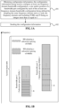
- FIG. 1B is a distribution schematic diagram of a frequency-domain bandwidth configuration according to the embodiment corresponding to FIG. 1A .
- the network device makes two frequency-domain bandwidth configurations for the terminal through first configuration information, each frequency-domain bandwidth configuration configuring a bandwidth part smaller than a system bandwidth for specific frequency-domain resource allocation.
- a bandwidth part 1 is a bandwidth part adopting a 15kHz subcarrier spacing, one RB includes 12 subcarriers, and a bandwidth is 180kHz.
- a bandwidth part 2 is a bandwidth part adopting a 60kHz subcarrier spacing, one RB includes 12 subcarriers, and a bandwidth is 720kHz.
- the same resource granularity i.e., the frequency-domain unit D
- the same resource granularity i.e., the frequency-domain unit D
- may be adopted for configuration which, compared with configuration of bandwidth parts by adopting different resource granularities, may unify control signaling structures, effectively ensure a relatively low control signaling overhead and, meanwhile, reduce processing complexity of the terminal.
- RBs corresponding to the maximum subcarrier spacing and a multiple thereof are adopted as the frequency-domain unit D, which, compared with adoption of RBs corresponding to a relatively small subcarrier spacing and a multiple thereof as the frequency-domain unit D, may reduce a bit number for configuration of the bandwidth parts and reduce the control signaling overhead.
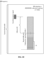
- FIG. 1C is a distribution schematic diagram of another frequency-domain bandwidth configuration according to the embodiment corresponding to FIG. 1A .
- a position of the bandwidth part 1 in FIG. 1B may specifically be indicated, an offset of a frequency-domain low end of the bandwidth part 1 relative to the center frequency point of the synchronization signal is adopted to configure the position of the bandwidth part 1, the frequency-domain unit D is adopted as a frequency-domain granularity for configuration, and the offset is 4D.
- the terminal may obtain information about the position of the bandwidth part 1 without learning the system bandwidth, so that a control signaling overhead in notifying the terminal of the system bandwidth by the network device may be effectively reduced, and bandwidth part configuration flexibility is improved.
- the terminal is not required to search a position of the system bandwidth, so that a requirement on processing complexity of the terminal is also reduced, and reduction in cost and power consumption of the terminal is facilitated.
- FIG. 1D is a distribution schematic diagram of another frequency-domain bandwidth configuration according to the embodiment corresponding to FIG. 1A .
- the position of the bandwidth part 1 in FIG. 1B may specifically be indicated, an offset of a center frequency point of the bandwidth part 1 relative to the center frequency point of the synchronization signal is adopted to configure the position of the bandwidth part 1, the frequency-domain unit D is adopted as a frequency-domain granularity for configuration, and the offset is 2D.
- the terminal may obtain the information about the position of the bandwidth part 1 without learning the system bandwidth, so that the control signaling overhead in notifying the terminal of the system bandwidth by the network device may be effectively reduced, and the bandwidth part configuration flexibility is improved.
- the terminal is not required to search the position of the system bandwidth, so that a requirement on processing complexity of the terminal is also reduced, and reduction in cost and power consumption of the terminal is facilitated.
- FIG. 1E is a distribution schematic diagram of another frequency-domain bandwidth configuration according to the embodiment corresponding to FIG. 1A .
- the position of the bandwidth part 1 in FIG. 1B may specifically be indicated, an offset of the frequency-domain low end of the bandwidth part 1 relative to the center frequency point of the cell carrier is adopted to configure the position of the bandwidth part 1, the frequency-domain unit D is adopted as a frequency-domain granularity for configuration, and the offset is 2D.
- positions of bandwidth parts 1 for all terminals in a cell are configured relative to the center frequency point of the cell carrier, which, compared with the embodiment corresponding to FIG. 1D , ensures that the offset of the bandwidth part 1 is not required to be indicated relative to different synchronization signals for a terminal reading different synchronization signals and may effectively reduce processing complexity of the network device.
- the configuration information is obtained, the configuration information being used to configure the at least one frequency-domain bandwidth configuration, the size and/or position of the bandwidth part configured by each of the at least one frequency-domain bandwidth configuration being defined by adopting the same frequency-domain unit as the unit, the frequency-domain unit including the N RBs and N being an integer more than or equal to 1, and the configuration information is further sent.
- the size and/or position of the bandwidth part configured by each frequency-domain bandwidth configuration are/is defined by adopting the same frequency-domain unit as the unit, which, compared with configuration of bandwidth parts by adopting different resource granularities, may unify control signaling structures, thereby effectively ensuring a relatively low control signaling overhead and reducing device complexity.
- the size and/or position of the bandwidth part configured by each frequency-domain bandwidth configuration are/is defined by adopting the same frequency-domain unit as the unit, which, compared with configuration of bandwidth parts by adopting different resource granularities, may unify control signaling structures, thereby reducing processing complexity of a terminal.
- the maximum subcarrier spacing in the subcarrier spacings of the bandwidth parts configured by each frequency-domain bandwidth configuration is adopted as the subcarrier spacing of the RB, which, compared with adoption of a relatively small subcarrier spacing as the subcarrier spacing of the RB, may effectively reduce a bit number for configuration of the bandwidth parts and reduce the control signaling overhead.
- the position of the bandwidth part may be configured by adopting the offset relative to the synchronization signal, and the terminal may obtain information about a position of a bandwidth part 1 without learning a system bandwidth, so that a control signaling overhead in notifying the terminal of the system bandwidth by the network device may be effectively reduced, and bandwidth part configuration flexibility is improved.
- the terminal is not required to search the position of the system bandwidth, so that a requirement on processing complexity of the terminal is also reduced, and reduction in cost and power consumption of the terminal is facilitated.
- FIG. 2 is a flowchart of another bandwidth part configuration method according to another embodiment of the disclosure, as shown in FIG. 2 .
- configuration information is received, the configuration information being used to configure at least one frequency-domain bandwidth configuration, a size and/or position of a bandwidth part configured by each of the at least one frequency-domain bandwidth configuration being defined by adopting the same frequency-domain unit as a unit, the frequency-domain unit including N RB s and N being an integer more than or equal to 1.
- the at least one frequency-domain bandwidth configuration is determined according to the configuration information.
- an execution body of 201 ⁇ 202 may be a terminal.
- the bandwidth part configured by each frequency-domain bandwidth configuration has the same subcarrier spacing or different subcarrier spacings. There are no particular limits made thereto in the embodiment.
- a subcarrier spacing of the RB may be any subcarrier spacing in the subcarrier spacings of the bandwidth part configured by each frequency-domain bandwidth configuration.
- the subcarrier spacing of the RB is a maximum subcarrier spacing in the subcarrier spacings of the bandwidth part configured by each frequency-domain bandwidth configuration.
- the maximum subcarrier spacing in the subcarrier spacings of the bandwidth parts configured by each frequency-domain bandwidth configuration is adopted as the subcarrier spacing of the RB, which, compared with adoption of a relatively small subcarrier spacing as the subcarrier spacing of the RB, may effectively reduce a bit number for configuration of the bandwidth parts and reduce a control signaling overhead.
- the size of the bandwidth part configured by each frequency-domain bandwidth configuration may be the number of frequency-domain units D in the bandwidth part configured by the frequency-domain bandwidth configuration.
- the position of the bandwidth part configured by each frequency-domain bandwidth configuration is a relative offset of the bandwidth part configured by the frequency-domain bandwidth configuration relative to a synchronization signal or a cell carrier, the relative offset being defined by adopting the frequency-domain unit.
- the position of the bandwidth part may be configured by adopting the offset relative to the synchronization signal, and the terminal may obtain information about a position of a bandwidth part 1 without learning a system bandwidth, so that a control signaling overhead in notifying the terminal of the system bandwidth by a network device may be effectively reduced, and bandwidth part configuration flexibility is improved.
- the terminal is not required to search the position of the system bandwidth, so that a requirement on processing complexity of the terminal is also reduced, and reduction in cost and power consumption of the terminal is facilitated.
- the relative offset may be an offset of a center frequency point, frequency-domain high end or frequency-domain low end of the bandwidth part configured by each frequency-domain bandwidth configuration relative to a center frequency point, frequency-domain high end or frequency-domain low end of the synchronization signal, for example, the offset of the center frequency point of the bandwidth part configured by each frequency-domain bandwidth configuration relative to the center frequency point of the synchronization signal, or, for another example, the offset of the center frequency point of the bandwidth part configured by each frequency-domain bandwidth configuration relative to the frequency-domain high end of the synchronization signal, or, for another example, the offset of the center frequency point of the bandwidth part configured by each frequency-domain bandwidth configuration relative to the frequency-domain low end of the synchronization signal, or, for another example, the offset of the frequency-domain high end of the bandwidth part configured by each frequency-domain bandwidth configuration relative to the center frequency point of the synchronization signal, or, for another example, the offset of the frequency-domain high end of the bandwidth part configured by each frequency-domain bandwidth configuration relative to the center frequency point of the
- the relative offset may be an offset of the center frequency point, frequency-domain high end or frequency-domain low end of the bandwidth part configured by each frequency-domain bandwidth configuration relative to a center frequency point, frequency-domain high end or frequency-domain low end of the cell carrier, for example, the offset of the center frequency point of the bandwidth part configured by each frequency-domain bandwidth configuration relative to the center frequency point of the cell carrier, or, for another example, the offset of the center frequency point of the bandwidth part configured by each frequency-domain bandwidth configuration relative to the frequency-domain high end of the cell carrier, or, for another example, the offset of the center frequency point of the bandwidth part configured by each frequency-domain bandwidth configuration relative to the frequency-domain low end of the cell carrier, or, for another example, the offset of the frequency-domain high end of the bandwidth part configured by each frequency-domain bandwidth configuration relative to the center frequency point of the cell carrier, or, for another example, the offset of the frequency-domain high end of the bandwidth part configured by each frequency-domain bandwidth configuration relative to the frequency-domain high end of the cell carrier, or, for another example, the
- the configuration information received in 201 may further include at least one of: serial number information of each frequency-domain bandwidth configuration; and information about the subcarrier spacings of the bandwidth part configured by each frequency-domain bandwidth configuration.
- the information about the subcarrier spacings of the bandwidth part configured by each frequency-domain bandwidth configuration may be information of serial numbers of the subcarrier spacings of the bandwidth part configured by each frequency-domain bandwidth configuration, or may also be information of a serial number of a parameter set of the bandwidth part configured by each frequency-domain bandwidth configuration, the parameter set of the bandwidth part configured by each frequency-domain bandwidth configuration at least including a subcarrier spacing and cyclic prefix of the bandwidth part configured by each frequency-domain bandwidth configuration, for example, a parameter set 1 (subcarrier spacing 1, cyclic prefix 1) and a parameter set 2 (subcarrier spacing 2, cyclic prefix 2).
- a parameter set 1 subcarrier spacing 1, cyclic prefix 1
- a parameter set 2 subcarrier spacing 2, cyclic prefix 2
- the configuration information sent through high-layer signaling or a system broadcast message may specifically be received.
- the terminal may specifically receive the configuration information sent by the network device through the high-layer signaling or the system broadcast message.
- the high-layer signaling may be an RRC message, and the configuration information may specifically be contained through an IE in the RRC message.
- the RRC message may be an RRC message in the conventional art, for example, an RRC connection reconfiguration message, and there are no limits made thereto in the embodiment.
- An IE of an existing RRC message is extended to contain the configuration information.
- the RRC message may also be different from the existing RRC message in the conventional art.
- the high-layer signaling may be a MAC CE message, and a new MAC CE message may also specifically be added to contain the configuration information.
- the configuration information may specifically be contained by a spare bit in an existing MIB or SIB in the system broadcast message, and a new SIB may also be added to contain the configuration information.
- first indication information may further be received, the first indication information including information of a serial number indicating one frequency-domain bandwidth configuration in the at least one frequency-domain bandwidth configuration. Therefore, the specific frequency-domain bandwidth configuration may be indicated to the terminal.
- the first indication information sent through high-layer signaling or a system broadcast message or DCI may specifically be received.
- second indication information may further be received, the second indication information including frequency-domain resource allocation information based on one frequency-domain bandwidth configuration in the at least one frequency-domain bandwidth configuration. Therefore, specific frequency-domain resource allocation information of the specific frequency-domain bandwidth configuration may be indicated to the terminal.
- the second indication information sent through high-layer signaling or a system broadcast message or DCI may specifically be received.
- the configuration information is received, the configuration information being used to configure the at least one frequency-domain bandwidth configuration, the size and/or position of the bandwidth part configured by each of the at least one frequency-domain bandwidth configuration being defined by adopting the same frequency-domain unit as the unit, the frequency-domain unit including the N RBs and N being an integer more than or equal to 1, and the at least one frequency-domain bandwidth configuration is further determined according to the configuration information.
- the size and/or position of the bandwidth part configured by each frequency-domain bandwidth configuration are/is defined by adopting the same frequency-domain unit as the unit, which, compared with configuration of bandwidth parts by adopting different resource granularities, may unify control signaling structures, thereby effectively ensuring a relatively low control signaling overhead and reducing device complexity.
- the size and/or position of the bandwidth part configured by each frequency-domain bandwidth configuration are/is defined by adopting the same frequency-domain unit as the unit, which, compared with configuration of bandwidth parts by adopting different resource granularities, may unify control signaling structures, thereby reducing processing complexity of a terminal.
- the maximum subcarrier spacing in the subcarrier spacings of the bandwidth parts configured by each frequency-domain bandwidth configuration is adopted as the subcarrier spacing of the RB, which, compared with adoption of a relatively small subcarrier spacing as the subcarrier spacing of the RB, may effectively reduce a bit number for configuration of the bandwidth parts and reduce the control signaling overhead.
- the position of the bandwidth part may be configured by adopting the offset relative to the synchronization signal, and the terminal may obtain information about the position of the bandwidth part 1 without learning the system bandwidth, so that a control signaling overhead in notifying the terminal of the system bandwidth by the network device may be effectively reduced, and bandwidth part configuration flexibility is improved.
- the terminal is not required to search the position of the system bandwidth, so that a requirement on processing complexity of the terminal is also reduced, and reduction in cost and power consumption of the terminal is facilitated.
- FIG. 3 is a structure diagram of a network device according to another embodiment of the disclosure, as shown in FIG. 3 .
- the network device of the embodiment may include an obtaining unit 31 and a sending unit 32.
- the obtaining unit 31 is configured to obtain configuration information, the configuration information being used to configure at least one frequency-domain bandwidth configuration, a size and/or position of a bandwidth part configured by each of the at least one frequency-domain bandwidth configuration being defined by adopting the same frequency-domain unit as a unit, the frequency-domain unit including N RBs and N being an integer more than or equal to 1.
- the sending unit 32 is configured to send the configuration information.
- the bandwidth part configured by each frequency-domain bandwidth configuration has the same subcarrier spacing or different subcarrier spacings. There are no particular limits made thereto in the embodiment.
- a subcarrier spacing of the RB may be any subcarrier spacing in the subcarrier spacings of the bandwidth part configured by each frequency-domain bandwidth configuration.
- the subcarrier spacing of the RB is a maximum subcarrier spacing in the subcarrier spacings of the bandwidth part configured by each frequency-domain bandwidth configuration.
- the maximum subcarrier spacing in the subcarrier spacings of the bandwidth parts configured by each frequency-domain bandwidth configuration is adopted as the subcarrier spacing of the RB, which, compared with adoption of a relatively small subcarrier spacing as the subcarrier spacing of the RB, may effectively reduce a bit number for configuration of the bandwidth parts and reduce a control signaling overhead.
- the size of the bandwidth part configured by each frequency-domain bandwidth configuration may be the number of frequency-domain units D in the bandwidth part configured by the frequency-domain bandwidth configuration.
- the position of the bandwidth part configured by each frequency-domain bandwidth configuration is a relative offset of the bandwidth part configured by the frequency-domain bandwidth configuration relative to a synchronization signal or a cell carrier, the relative offset being defined by adopting the frequency-domain unit.
- the relative offset may be an offset of a center frequency point, frequency-domain high end or frequency-domain low end of the bandwidth part configured by each frequency-domain bandwidth configuration relative to a center frequency point, frequency-domain high end or frequency-domain low end of the synchronization signal,
- the relative offset may be an offset of the center frequency point, frequency-domain high end or frequency-domain low end of the bandwidth part configured by each frequency-domain bandwidth configuration relative to a center frequency point, frequency-domain high end or frequency-domain low end of the cell carrier,
- the configuration information obtained by the obtaining unit 21 may further include at least one of: serial number information of each frequency-domain bandwidth configuration; and information about the subcarrier spacings of the bandwidth part configured by each frequency-domain bandwidth configuration.
- the information about the subcarrier spacings of the bandwidth part configured by each frequency-domain bandwidth configuration may be information of serial numbers of the subcarrier spacings of the bandwidth part configured by each frequency-domain bandwidth configuration, or may also be information of a serial number of a parameter set of the bandwidth part configured by each frequency-domain bandwidth configuration, the parameter set of the bandwidth part configured by each frequency-domain bandwidth configuration at least including a subcarrier spacing and cyclic prefix of the bandwidth part configured by each frequency-domain bandwidth configuration, for example, a parameter set 1 (subcarrier spacing 1, cyclic prefix 1) and a parameter set 2 (subcarrier spacing 2, cyclic prefix 2).
- a parameter set 1 subcarrier spacing 1, cyclic prefix 1
- a parameter set 2 subcarrier spacing 2, cyclic prefix 2
- the sending unit 22 may specifically be configured to send the configuration information through high-layer signaling or a system broadcast message.
- the sending unit 22 may further be configured to send first indication information, the first indication information including information of a serial number indicating one frequency-domain bandwidth configuration in the at least one frequency-domain bandwidth configuration.
- the sending unit 22 may specifically be configured to send the first indication information through high-layer signaling or a system broadcast message or DCI.
- the sending unit 22 may further be configured to send second indication information, the second indication information including frequency-domain resource allocation information based on one frequency-domain bandwidth configuration in the at least one frequency-domain bandwidth configuration.
- the sending unit 22 may specifically be configured to send the second indication information through high-layer signaling or a system broadcast message or DCI.
- the configuration information is obtained through the obtaining unit, the configuration information being used to configure the at least one frequency-domain bandwidth configuration, the size and/or position of the bandwidth part configured by each of the at least one frequency-domain bandwidth configuration being defined by adopting the same frequency-domain unit as the unit, the frequency-domain unit including the N RBs and N being an integer more than or equal to 1, and the configuration information is further sent through the sending unit.
- the size and/or position of the bandwidth part configured by each frequency-domain bandwidth configuration are/is defined by adopting the same frequency-domain unit as the unit, which, compared with configuration of bandwidth parts by adopting different resource granularities, may unify control signaling structures, thereby effectively ensuring a relatively low control signaling overhead and reducing device complexity.
- the size and/or position of the bandwidth part configured by each frequency-domain bandwidth configuration are/is defined by adopting the same frequency-domain unit as the unit, which, compared with configuration of bandwidth parts by adopting different resource granularities, may unify control signaling structures, thereby reducing processing complexity of a terminal.
- the maximum subcarrier spacing in the subcarrier spacings of the bandwidth parts configured by each frequency-domain bandwidth configuration is adopted as the subcarrier spacing of the RB, which, compared with adoption of a relatively small subcarrier spacing as the subcarrier spacing of the RB, may effectively reduce a bit number for configuration of the bandwidth parts and reduce the control signaling overhead.
- the position of the bandwidth part may be configured by adopting the offset relative to the synchronization signal, and a terminal may obtain information about a position of a bandwidth part 1 without learning a system bandwidth, so that a control signaling overhead in notifying the terminal of the system bandwidth by the network device may be effectively reduced, and bandwidth part configuration flexibility is improved.
- the terminal is not required to search the position of the system bandwidth, so that a requirement on processing complexity of the terminal is also reduced, and reduction in cost and power consumption of the terminal is facilitated.
- FIG. 4 is a structure diagram of a terminal according to another embodiment of the disclosure, as shown in FIG. 4 .
- the network device of the embodiment may include a receiving unit 41 and a determination unit 42.
- the receiving unit 41 is configured to receive configuration information, the configuration information being used to configure at least one frequency-domain bandwidth configuration, a size and/or position of a bandwidth part configured by each of the at least one frequency-domain bandwidth configuration being defined by adopting the same frequency-domain unit as a unit, the frequency-domain unit including N RBs and N being an integer more than or equal to 1.
- the determination unit 42 is configured to determine the at least one frequency-domain bandwidth configuration according to the configuration information.
- the bandwidth part configured by each frequency-domain bandwidth configuration has the same subcarrier spacing or different subcarrier spacings. There are no particular limits made thereto in the embodiment.
- a subcarrier spacing of the RB may be any subcarrier spacing in the subcarrier spacings of the bandwidth part configured by each frequency-domain bandwidth configuration.
- the subcarrier spacing of the RB is a maximum subcarrier spacing in the subcarrier spacings of the bandwidth part configured by each frequency-domain bandwidth configuration.
- the maximum subcarrier spacing in the subcarrier spacings of the bandwidth parts configured by each frequency-domain bandwidth configuration is adopted as the subcarrier spacing of the RB, which, compared with adoption of a relatively small subcarrier spacing as the subcarrier spacing of the RB, may effectively reduce a bit number for configuration of the bandwidth parts and reduce a control signaling overhead.
- the size of the bandwidth part configured by each frequency-domain bandwidth configuration may be the number of frequency-domain units D in the bandwidth part configured by the frequency-domain bandwidth configuration.
- the position of the bandwidth part configured by each frequency-domain bandwidth configuration is a relative offset of the bandwidth part configured by the frequency-domain bandwidth configuration relative to a synchronization signal or a cell carrier, the relative offset being defined by adopting the frequency-domain unit.
- the relative offset may be an offset of a center frequency point, frequency-domain high end or frequency-domain low end of the bandwidth part configured by each frequency-domain bandwidth configuration relative to a center frequency point, frequency-domain high end or frequency-domain low end of the synchronization signal.
- the relative offset may be an offset of the center frequency point, frequency-domain high end or frequency-domain low end of the bandwidth part configured by each frequency-domain bandwidth configuration relative to a center frequency point, frequency-domain high end or frequency-domain low end of the cell carrier,
- the configuration information received by the receiving unit 41 may further include at least one of: serial number information of each frequency-domain bandwidth configuration; and information about the subcarrier spacings of the bandwidth part configured by each frequency-domain bandwidth configuration.
- the information about the subcarrier spacings of the bandwidth part configured by each frequency-domain bandwidth configuration may be information of serial numbers of the subcarrier spacings of the bandwidth part configured by each frequency-domain bandwidth configuration, or may also be information of a serial number of a parameter set of the bandwidth part configured by each frequency-domain bandwidth configuration, the parameter set of the bandwidth part configured by each frequency-domain bandwidth configuration at least including a subcarrier spacing and cyclic prefix of the bandwidth part configured by each frequency-domain bandwidth configuration, for example, a parameter set 1 (subcarrier spacing 1, cyclic prefix 1) and a parameter set 2 (subcarrier spacing 2, cyclic prefix 2).
- a parameter set 1 subcarrier spacing 1, cyclic prefix 1
- a parameter set 2 subcarrier spacing 2, cyclic prefix 2
- the receiving unit 31 may specifically be configured to receive the configuration information sent through high-layer signaling or a system broadcast message.
- the receiving unit 31 may further be configured to receive first indication information, the first indication information including information of a serial number indicating one frequency-domain bandwidth configuration in the at least one frequency-domain bandwidth configuration.
- the receiving unit 31 may specifically be configured to receive the first indication information sent through high-layer signaling or a system broadcast message or DCI.
- the receiving unit 31 may further be configured to receive second indication information, the second indication information including frequency-domain resource allocation information based on one frequency-domain bandwidth configuration in the at least one frequency-domain bandwidth configuration.
- the receiving unit 31 may specifically be configured to receive the second indication information sent through high-layer signaling or a system broadcast message or DCI.
- the configuration information is received through the receiving unit, the configuration information being used to configure the at least one frequency-domain bandwidth configuration, the size and/or position of the bandwidth part configured by each of the at least one frequency-domain bandwidth configuration being defined by adopting the same frequency-domain unit as the unit, the frequency-domain unit including the N RBs and N being an integer more than or equal to 1, and the at least one frequency-domain bandwidth configuration is further determined through the determination unit according to the configuration information.
- the size and/or position of the bandwidth part configured by each frequency-domain bandwidth configuration are/is defined by adopting the same frequency-domain unit as the unit, which, compared with configuration of bandwidth parts by adopting different resource granularities, may unify control signaling structures, thereby effectively ensuring a relatively low control signaling overhead and reducing device complexity.
- the size and/or position of the bandwidth part configured by each frequency-domain bandwidth configuration are/is defined by adopting the same frequency-domain unit as the unit, which, compared with configuration of bandwidth parts by adopting different resource granularities, may unify control signaling structures, thereby reducing processing complexity of a terminal.
- the maximum subcarrier spacing in the subcarrier spacings of the bandwidth parts configured by each frequency-domain bandwidth configuration is adopted as the subcarrier spacing of the RB, which, compared with adoption of a relatively small subcarrier spacing as the subcarrier spacing of the RB, may effectively reduce a bit number for configuration of the bandwidth parts and reduce the control signaling overhead.
- the position of the bandwidth part may be configured by adopting the offset relative to the synchronization signal, and the terminal may obtain information about a position of a bandwidth part 1 without learning a system bandwidth, so that a control signaling overhead in notifying the terminal of the system bandwidth by the network device may be effectively reduced, and bandwidth part configuration flexibility is improved.
- the terminal is not required to search the position of the system bandwidth, so that a requirement on processing complexity of the terminal is also reduced, and reduction in cost and power consumption of the terminal is facilitated.
- the disclosed system, device and method may be implemented in another manner.
- the device embodiment described above is only schematic, and for example, division of the units is only logic function division, and other division manners may be adopted during practical implementation.
- multiple units or components may be combined or integrated into another system, or some characteristics may be neglected or not executed.
- coupling or direct coupling or communication connection between each displayed or discussed component may be indirect coupling or communication connection, implemented through some interfaces, of the device or the units, and may be electrical and mechanical or adopt other forms.
- the units described as separate parts may or may not be physically separated, and parts displayed as units may or may not be physical units, and namely may be located in the same place, or may also be distributed to multiple network units. Part or all of the units may be selected to achieve the purpose of the solutions of the embodiments according to a practical requirement.
- each function unit in each embodiment of the disclosure may be integrated into a processing unit, each unit may also exist independently, and two or more than two units may also be integrated into a unit.
- the integrated unit may be implemented in a hardware form and may also be implemented in form of hardware and software functional unit.
- a method for bandwidth part configuration including: obtaining configuration information, the configuration information being used to configure at least one frequency-domain bandwidth configuration, a size and/or position of a bandwidth part configured by each of the at least one frequency-domain bandwidth configuration being defined by adopting a same frequency-domain unit as a unit, the frequency-domain unit includes N Resource Blocks (RBs) and N being an integer more than or equal to 1; and sending the configuration information.
- RBs Resource Blocks
- the bandwidth part configured by each frequency-domain bandwidth configuration has a same subcarrier spacing or different subcarrier spacings.
- a subcarrier spacing of the RB is any subcarrier spacing in the subcarrier spacings of the bandwidth part configured by each frequency-domain bandwidth configuration; or the subcarrier spacing of the RB is a maximum subcarrier spacing in the subcarrier spacings of the bandwidth part configured by each frequency-domain bandwidth configuration.
- the size of the bandwidth part configured by each frequency-domain bandwidth configuration is a number of frequency-domain units in the bandwidth part configured by the frequency-domain bandwidth configuration.
- the position of the bandwidth part configured by each frequency-domain bandwidth configuration is a relative offset of the bandwidth part configured by the frequency-domain bandwidth configuration relative to a synchronization signal or a cell carrier, the relative offset being defined by adopting the frequency-domain unit.
- the relative offset includes: an offset of a center frequency point, frequency-domain high end or frequency-domain low end of the bandwidth part configured by each frequency-domain bandwidth configuration relative to a center frequency point, frequency-domain high end or frequency-domain low end of the synchronization signal; or an offset of the center frequency point, frequency-domain high end or frequency-domain low end of the bandwidth part configured by each frequency-domain bandwidth configuration relative to a center frequency point, frequency-domain high end or frequency-domain low end of the cell carrier.
- the configuration information further includes at least one of: serial number information of each frequency-domain bandwidth configuration; and information about the subcarrier spacings of the bandwidth part configured by each frequency-domain bandwidth configuration.
- information about the subcarrier spacings of the bandwidth part configured by each frequency-domain bandwidth configuration includes: information of serial numbers of the subcarrier spacings of the bandwidth part configured by each frequency-domain bandwidth configuration; or information of a serial number of a parameter set of the bandwidth part configured by each frequency-domain bandwidth configuration, the parameter set of the bandwidth part configured by each frequency-domain bandwidth configuration at least includes a subcarrier spacing and cyclic prefix of the bandwidth part configured by each frequency-domain bandwidth configuration.
- sending the configuration information includes: sending the configuration information through high-layer signaling or a system broadcast message.
- the method further includes: sending first indication information, the first indication information includes information of a serial number indicating one frequency-domain bandwidth configuration in the at least one frequency-domain bandwidth configuration.
- sending the first indication information includes: sending the first indication information through high-layer signaling or a system broadcast message or Downlink Control Information (DCI).
- DCI Downlink Control Information
- the method further includes: sending second indication information, the second indication information includes frequency-domain resource allocation information based on one frequency-domain bandwidth configuration in the at least one frequency-domain bandwidth configuration.
- sending the second indication information includes: sending the second indication information through high-layer signaling or a system broadcast message or Downlink Control Information (DCI).
- DCI Downlink Control Information
- a method for bandwidth part configuration including: receiving configuration information, the configuration information being used to configure at least one frequency-domain bandwidth configuration, a size and/or position of a bandwidth part configured by each of the at least one frequency-domain bandwidth configuration being defined by adopting a same frequency-domain unit as a unit, the frequency-domain unit includes N Resource Blocks (RBs) and N being an integer more than or equal to 1; and determining the at least one frequency-domain bandwidth configuration according to the configuration information.
- RBs Resource Blocks
- the bandwidth part configured by each frequency-domain bandwidth configuration has a same subcarrier spacing or different subcarrier spacings.
- a subcarrier spacing of the RB is any subcarrier spacing in the subcarrier spacings of the bandwidth part configured by each frequency-domain bandwidth configuration; or the subcarrier spacing of the RB is a maximum subcarrier spacing in the subcarrier spacings of the bandwidth part configured by each frequency-domain bandwidth configuration.
- the size of the bandwidth part configured by each frequency-domain bandwidth configuration is a number of frequency-domain units in the bandwidth part configured by the frequency-domain bandwidth configuration.
- the position of the bandwidth part configured by each frequency-domain bandwidth configuration is a relative offset of the bandwidth part configured by the frequency-domain bandwidth configuration relative to a synchronization signal or a cell carrier, the relative offset being defined by adopting the frequency-domain unit.
- the relative offset includes: an offset of a center frequency point, frequency-domain high end or frequency-domain low end of the bandwidth part configured by each frequency-domain bandwidth configuration relative to a center frequency point, frequency-domain high end or frequency-domain low end of the synchronization signal; or an offset of the center frequency point, frequency-domain high end or frequency-domain low end of the bandwidth part configured by each frequency-domain bandwidth configuration relative to a center frequency point, frequency-domain high end or frequency-domain low end of the cell carrier.
- the configuration information further includes at least one of: serial number information of each frequency-domain bandwidth configuration; and information about the subcarrier spacings of the bandwidth part configured by each frequency-domain bandwidth configuration.
- information about the subcarrier spacings of the bandwidth part configured by each frequency-domain bandwidth configuration includes: information of serial numbers of the subcarrier spacings of the bandwidth part configured by each frequency-domain bandwidth configuration; or information of a serial number of a parameter set of the bandwidth part configured by each frequency-domain bandwidth configuration, the parameter set of the bandwidth part configured by each frequency-domain bandwidth configuration at least includes a subcarrier spacing and cyclic prefix of the bandwidth part configured by each frequency-domain bandwidth configuration.
- receiving the configuration information includes: receiving the configuration information sent through high-layer signaling or a system broadcast message.
- the method further includes: receiving first indication information, the first indication information includes information of a serial number indicating one frequency-domain bandwidth configuration in the at least one frequency-domain bandwidth configuration.
- receiving the first indication information includes: receiving the first indication information sent through high-layer signaling or a system broadcast message or Downlink Control Information (DCI).
- DCI Downlink Control Information
- the method further includes: receiving second indication information, the second indication information includes frequency-domain resource allocation information based on one frequency-domain bandwidth configuration in the at least one frequency-domain bandwidth configuration.
- receiving the second indication information includes: receiving the second indication information sent through high-layer signaling or a system broadcast message or Downlink Control Information (DCI).
- DCI Downlink Control Information
- a network device including: an obtaining unit, configured to obtain configuration information, the configuration information being used to configure at least one frequency-domain bandwidth configuration, a size and/or position of a bandwidth part configured by each of the at least one frequency-domain bandwidth configuration being defined by adopting a same frequency-domain unit as a unit, the frequency-domain unit includes N Resource Blocks (RBs) and N being an integer more than or equal to 1; and a sending unit, configured to send the configuration information.
- RBs Resource Blocks
- the bandwidth part configured by each frequency-domain bandwidth configuration has a same subcarrier spacing or different subcarrier spacings.
- a subcarrier spacing of the RB is any subcarrier spacing in the subcarrier spacings of the bandwidth part configured by each frequency-domain bandwidth configuration; or the subcarrier spacing of the RB is a maximum subcarrier spacing in the subcarrier spacings of the bandwidth part configured by each frequency-domain bandwidth configuration.
- the size of the bandwidth part configured by each frequency-domain bandwidth configuration is a number of frequency-domain units in the bandwidth part configured by the frequency-domain bandwidth configuration.
- the position of the bandwidth part configured by each frequency-domain bandwidth configuration is a relative offset of the bandwidth part configured by the frequency-domain bandwidth configuration relative to a synchronization signal or a cell carrier, the relative offset being defined by adopting the frequency-domain unit.
- the configuration information further includes at least one of: serial number information of each frequency-domain bandwidth configuration; and information about the subcarrier spacings of the bandwidth part configured by each frequency-domain bandwidth configuration.
- information about the subcarrier spacings of the bandwidth part configured by each frequency-domain bandwidth configuration includes: information of serial numbers of the subcarrier spacings of the bandwidth part configured by each frequency-domain bandwidth configuration; or information of a serial number of a parameter set of the bandwidth part configured by each frequency-domain bandwidth configuration, the parameter set of the bandwidth part configured by each frequency-domain bandwidth configuration at least includes a subcarrier spacing and cyclic prefix of the bandwidth part configured by each frequency-domain bandwidth configuration.
- the sending unit is specifically configured to: send the configuration information through high-layer signaling or a system broadcast message.
- the sending unit is further configured to: send first indication information, the first indication information includes information of a serial number indicating one frequency-domain bandwidth configuration in the at least one frequency-domain bandwidth configuration.
- the sending unit is specifically configured to: send the first indication information through high-layer signaling or a system broadcast message or Downlink Control Information (DCI).
- DCI Downlink Control Information
- the sending unit is further configured to: send second indication information, the second indication information includes frequency-domain resource allocation information based on one frequency-domain bandwidth configuration in the at least one frequency-domain bandwidth configuration.
- the sending unit is specifically configured to: send the second indication information through high-layer signaling or a system broadcast message or Downlink Control Information (DCI).
- DCI Downlink Control Information
- a terminal including: a receiving unit, configured to receive configuration information, the configuration information being used to configure at least one frequency-domain bandwidth configuration, a size and/or position of a bandwidth part configured by each of the at least one frequency-domain bandwidth configuration being defined by adopting a same frequency-domain unit as a unit, the frequency-domain unit includes N Resource Blocks (RBs) and N being an integer more than or equal to 1; and a determination unit, configured to determine the at least one frequency-domain bandwidth configuration according to the configuration information.
- RBs Resource Blocks
- the bandwidth part configured by each frequency-domain bandwidth configuration has a same subcarrier spacing or different subcarrier spacings.
- a subcarrier spacing of the RB is any subcarrier spacing in the subcarrier spacings of the bandwidth part configured by each frequency-domain bandwidth configuration; or the subcarrier spacing of the RB is a maximum subcarrier spacing in the subcarrier spacings of the bandwidth part configured by each frequency-domain bandwidth configuration.
- the size of the bandwidth part configured by each frequency-domain bandwidth configuration is a number of frequency-domain units in the bandwidth part configured by the frequency-domain bandwidth configuration.
- the position of the bandwidth part configured by each frequency-domain bandwidth configuration is a relative offset of the bandwidth part configured by the frequency-domain bandwidth configuration relative to a synchronization signal or a cell carrier, the relative offset being defined by adopting the frequency-domain unit.
- the relative offset includes: an offset of a center frequency point, frequency-domain high end or frequency-domain low end of the bandwidth part configured by each frequency-domain bandwidth configuration relative to a center frequency point, frequency-domain high end or frequency-domain low end of the synchronization signal; or an offset of the center frequency point, frequency-domain high end or frequency-domain low end of the bandwidth part configured by each frequency-domain bandwidth configuration relative to a center frequency point, frequency-domain high end or frequency-domain low end of the cell carrier.
- the configuration information further includes at least one of: serial number information of each frequency-domain bandwidth configuration; and information about the subcarrier spacings of the bandwidth part configured by each frequency-domain bandwidth configuration.
- information about the subcarrier spacings of the bandwidth part configured by each frequency-domain bandwidth configuration includes: information of serial numbers of the subcarrier spacings of the bandwidth part configured by each frequency-domain bandwidth configuration; or information of a serial number of a parameter set of the bandwidth part configured by each frequency-domain bandwidth configuration, the parameter set of the bandwidth part configured by each frequency-domain bandwidth configuration at least includes a subcarrier spacing and cyclic prefix of the bandwidth part configured by each frequency-domain bandwidth configuration.
- the receiving unit is configured to: receive the configuration information sent through high-layer signaling or a system broadcast message.
- the receiving unit is further configured to: receive first indication information, the first indication information includes information of a serial number indicating one frequency-domain bandwidth configuration in the at least one frequency-domain bandwidth configuration.
- the receiving unit is configured to: receive the first indication information sent through high-layer signaling or a system broadcast message or Downlink Control Information (DCI).
- DCI Downlink Control Information
- the receiving unit is further configured to: receive second indication information, the second indication information includes frequency-domain resource allocation information based on one frequency-domain bandwidth configuration in the at least one frequency-domain bandwidth configuration.
- the receiving unit is configured to: receive the second indication information sent through high-layer signaling or a system broadcast message or Downlink Control Information (DCI).
- DCI Downlink Control Information
Landscapes
- Engineering & Computer Science (AREA)
- Signal Processing (AREA)
- Computer Networks & Wireless Communication (AREA)
- Quality & Reliability (AREA)
- Physics & Mathematics (AREA)
- Mathematical Physics (AREA)
- Computer Security & Cryptography (AREA)
- Mobile Radio Communication Systems (AREA)
- Data Exchanges In Wide-Area Networks (AREA)
Priority Applications (1)
| Application Number | Priority Date | Filing Date | Title |
|---|---|---|---|
| EP23203249.0A EP4284105B1 (de) | 2017-06-13 | 2017-06-13 | Konfiguration für bandbreitenteil |
Applications Claiming Priority (3)
| Application Number | Priority Date | Filing Date | Title |
|---|---|---|---|
| EP23203249.0A EP4284105B1 (de) | 2017-06-13 | 2017-06-13 | Konfiguration für bandbreitenteil |
| PCT/CN2017/088056 WO2018227371A1 (zh) | 2017-06-13 | 2017-06-13 | 带宽分段的配置方法及网络设备、终端 |
| EP17913269.1A EP3624521B1 (de) | 2017-06-13 | 2017-06-13 | Konfiguration für bandbreitenteil |
Related Parent Applications (2)
| Application Number | Title | Priority Date | Filing Date |
|---|---|---|---|
| EP17913269.1A Division EP3624521B1 (de) | 2017-06-13 | 2017-06-13 | Konfiguration für bandbreitenteil |
| EP17913269.1A Division-Into EP3624521B1 (de) | 2017-06-13 | 2017-06-13 | Konfiguration für bandbreitenteil |
Publications (3)
| Publication Number | Publication Date |
|---|---|
| EP4284105A2 true EP4284105A2 (de) | 2023-11-29 |
| EP4284105A3 EP4284105A3 (de) | 2023-12-06 |
| EP4284105B1 EP4284105B1 (de) | 2026-04-22 |
Family
ID=64659748
Family Applications (2)
| Application Number | Title | Priority Date | Filing Date |
|---|---|---|---|
| EP23203249.0A Active EP4284105B1 (de) | 2017-06-13 | 2017-06-13 | Konfiguration für bandbreitenteil |
| EP17913269.1A Active EP3624521B1 (de) | 2017-06-13 | 2017-06-13 | Konfiguration für bandbreitenteil |
Family Applications After (1)
| Application Number | Title | Priority Date | Filing Date |
|---|---|---|---|
| EP17913269.1A Active EP3624521B1 (de) | 2017-06-13 | 2017-06-13 | Konfiguration für bandbreitenteil |
Country Status (16)
| Country | Link |
|---|---|
| US (3) | US20200296725A1 (de) |
| EP (2) | EP4284105B1 (de) |
| JP (2) | JP2020528228A (de) |
| KR (2) | KR102403239B1 (de) |
| CN (2) | CN110612761B (de) |
| AU (1) | AU2017418863B2 (de) |
| CA (1) | CA3066295C (de) |
| IL (1) | IL271177B2 (de) |
| MX (1) | MX2019014728A (de) |
| MY (1) | MY204372A (de) |
| PH (1) | PH12019502680A1 (de) |
| RU (1) | RU2734024C1 (de) |
| SG (1) | SG11201911835WA (de) |
| TW (1) | TWI759492B (de) |
| WO (1) | WO2018227371A1 (de) |
| ZA (1) | ZA201908101B (de) |
Cited By (1)
| Publication number | Priority date | Publication date | Assignee | Title |
|---|---|---|---|---|
| US12185324B2 (en) * | 2017-06-16 | 2024-12-31 | Guangdong Oppo Mobile Telecommunications Corp., Ltd. | Wireless communication method and device |
Families Citing this family (6)
| Publication number | Priority date | Publication date | Assignee | Title |
|---|---|---|---|---|
| CA3066295C (en) * | 2017-06-13 | 2023-08-22 | Guangdong Oppo Mobile Telecommunications Corp., Ltd. | Bandwidth part configuration method, network device, and terminal |
| WO2019095251A1 (en) * | 2017-11-17 | 2019-05-23 | Qualcomm Incorporated | Control plane design for bandwidth part in new radio |
| CN115701191A (zh) * | 2021-07-23 | 2023-02-07 | 华为技术有限公司 | 一种配置方法及通信装置 |
| US20240147443A1 (en) * | 2022-10-28 | 2024-05-02 | Nokia Technologies Oy | Coexistence in telecommunication systems |
| WO2024173317A1 (en) | 2023-02-14 | 2024-08-22 | Interdigital Patent Holdings, Inc. | Conditional trigger for flight path update indication |
| KR20250144987A (ko) | 2023-02-14 | 2025-10-13 | 인터디지탈 패튼 홀딩스, 인크 | 비행 경로 상태에 대한 명시적 요청 |
Family Cites Families (15)
| Publication number | Priority date | Publication date | Assignee | Title |
|---|---|---|---|---|
| CN1501592A (zh) * | 2002-11-19 | 2004-06-02 | 电子科技大学 | 一种新的用于通信技术的多址方法 |
| US9276710B2 (en) * | 2009-12-21 | 2016-03-01 | Qualcomm Incorporated | Method and apparatus for resource allocation with carrier extension |
| WO2011083876A1 (en) * | 2010-01-07 | 2011-07-14 | Nec Corporation | Channel estimation for ofdm systems |
| CN102244631B (zh) * | 2010-05-11 | 2014-12-17 | 华为技术有限公司 | 一种中心子载波的配置方法和设备 |
| CN102143534B (zh) * | 2010-12-31 | 2014-03-12 | 华为技术有限公司 | 带宽控制的处理方法、设备及系统 |
| WO2012148161A2 (ko) | 2011-04-26 | 2012-11-01 | 엘지전자 주식회사 | 무선 접속 시스템에서 채널 상태 정보 전송 방법 및 이를 위한 단말 |
| KR20150009956A (ko) * | 2012-04-20 | 2015-01-27 | 엘지전자 주식회사 | 채널 상태 보고 방법 및 이를 위한 장치 |
| US9622230B2 (en) * | 2012-05-17 | 2017-04-11 | Qualcomm Incorporated | Narrow band partitioning and efficient resource allocation for low cost user equipments |
| CN103973392B (zh) * | 2013-01-24 | 2018-12-21 | 中兴通讯股份有限公司 | 参数发送方法和装置、上行解调参考信号发射方法和装置 |
| US10038581B2 (en) * | 2015-06-01 | 2018-07-31 | Huawei Technologies Co., Ltd. | System and scheme of scalable OFDM numerology |
| US11102775B2 (en) * | 2015-11-26 | 2021-08-24 | Huawei Technologies Co., Ltd. | Resource block channelization for OFDM-based numerologies |
| JP6462179B2 (ja) * | 2016-02-23 | 2019-01-30 | 京セラ株式会社 | 無線端末、基地局、及び方法 |
| US11483810B2 (en) * | 2017-04-03 | 2022-10-25 | Huawei Technologies Co., Ltd. | Methods and systems for resource configuration of wireless communication systems |
| DE112018000222T5 (de) * | 2017-05-05 | 2019-09-05 | Intel IP Corporation | Erzeugen und Zuordnen von RS(Referenz-Signal)-Sequenz und Vorkodiererzuteilung für NR (Neuer Funk) |
| CA3066295C (en) * | 2017-06-13 | 2023-08-22 | Guangdong Oppo Mobile Telecommunications Corp., Ltd. | Bandwidth part configuration method, network device, and terminal |
-
2017
- 2017-06-13 CA CA3066295A patent/CA3066295C/en active Active
- 2017-06-13 EP EP23203249.0A patent/EP4284105B1/de active Active
- 2017-06-13 CN CN201780090435.1A patent/CN110612761B/zh active Active
- 2017-06-13 WO PCT/CN2017/088056 patent/WO2018227371A1/zh not_active Ceased
- 2017-06-13 MY MYPI2019006878A patent/MY204372A/en unknown
- 2017-06-13 JP JP2019566136A patent/JP2020528228A/ja active Pending
- 2017-06-13 CN CN201911324534.9A patent/CN111031579B/zh active Active
- 2017-06-13 AU AU2017418863A patent/AU2017418863B2/en active Active
- 2017-06-13 KR KR1020197036094A patent/KR102403239B1/ko active Active
- 2017-06-13 IL IL271177A patent/IL271177B2/en unknown
- 2017-06-13 SG SG11201911835WA patent/SG11201911835WA/en unknown
- 2017-06-13 KR KR1020227017537A patent/KR102452101B1/ko active Active
- 2017-06-13 EP EP17913269.1A patent/EP3624521B1/de active Active
- 2017-06-13 MX MX2019014728A patent/MX2019014728A/es unknown
- 2017-06-13 RU RU2019141848A patent/RU2734024C1/ru active
-
2018
- 2018-05-30 TW TW107118395A patent/TWI759492B/zh active
-
2019
- 2019-11-27 US US16/698,888 patent/US20200296725A1/en not_active Abandoned
- 2019-11-27 PH PH12019502680A patent/PH12019502680A1/en unknown
- 2019-12-05 ZA ZA2019/08101A patent/ZA201908101B/en unknown
-
2020
- 2020-09-15 US US17/021,772 patent/US11259305B2/en active Active
-
2022
- 2022-01-27 US US17/585,843 patent/US12133207B2/en active Active
- 2022-07-04 JP JP2022108040A patent/JP7407244B2/ja active Active
Cited By (1)
| Publication number | Priority date | Publication date | Assignee | Title |
|---|---|---|---|---|
| US12185324B2 (en) * | 2017-06-16 | 2024-12-31 | Guangdong Oppo Mobile Telecommunications Corp., Ltd. | Wireless communication method and device |
Also Published As
Similar Documents
| Publication | Publication Date | Title |
|---|---|---|
| EP4284105A2 (de) | Konfiguration für bandbreitenteil | |
| US20200021420A1 (en) | Resource configuration method, method for determining bandwidth part, method for indicating bandwidth part, and device | |
| US11323226B2 (en) | Method for allocating control resource set, method for acquiring control resource set, base station, user equipment and readable medium | |
| CN108631986B (zh) | 一种确定下行控制信道dmrs资源的方法和装置 | |
| US11206099B2 (en) | Slot format indication method and related product | |
| US20230337206A1 (en) | Information transmission method and apparatus, iab node, and network device | |
| CN107371249B (zh) | 传输参数的配置方法及基站、信息传输方法及终端 | |
| US11470627B2 (en) | Uplink information sending method and apparatus, and uplink information receiving method and apparatus | |
| EP3641174A1 (de) | Übertragungsverfahren für referenzsignalmuster und vorrichtung dafür | |
| CN110495119B (zh) | 下行控制信道的配置方法及网络设备、终端 | |
| CN112399431A (zh) | 动态资源配置方法、处理业务的方法及装置 | |
| BR112019025153B1 (pt) | Método de configuração de parte de largura de banda e terminal | |
| CN120090913A (zh) | 数据传输方法、通信节点及存储介质 |
Legal Events
| Date | Code | Title | Description |
|---|---|---|---|
| PUAI | Public reference made under article 153(3) epc to a published international application that has entered the european phase |
Free format text: ORIGINAL CODE: 0009012 |
|
| STAA | Information on the status of an ep patent application or granted ep patent |
Free format text: STATUS: THE APPLICATION HAS BEEN PUBLISHED |
|
| REG | Reference to a national code |
Ref country code: DE Ref legal event code: R079 Free format text: PREVIOUS MAIN CLASS: H04W0072230000 Ipc: H04W0072045300 Ref country code: DE Ref legal event code: R079 Ref document number: 602017094991 Country of ref document: DE Free format text: PREVIOUS MAIN CLASS: H04W0072230000 Ipc: H04W0072045300 |
|
| PUAL | Search report despatched |
Free format text: ORIGINAL CODE: 0009013 |
|
| AC | Divisional application: reference to earlier application |
Ref document number: 3624521 Country of ref document: EP Kind code of ref document: P |
|
| AK | Designated contracting states |
Kind code of ref document: A2 Designated state(s): AL AT BE BG CH CY CZ DE DK EE ES FI FR GB GR HR HU IE IS IT LI LT LU LV MC MK MT NL NO PL PT RO RS SE SI SK SM TR |
|
| AK | Designated contracting states |
Kind code of ref document: A3 Designated state(s): AL AT BE BG CH CY CZ DE DK EE ES FI FR GB GR HR HU IE IS IT LI LT LU LV MC MK MT NL NO PL PT RO RS SE SI SK SM TR |
|
| RIC1 | Information provided on ipc code assigned before grant |
Ipc: H04W 72/23 20230101ALN20231031BHEP Ipc: H04W 72/0453 20230101AFI20231031BHEP |
|
| STAA | Information on the status of an ep patent application or granted ep patent |
Free format text: STATUS: REQUEST FOR EXAMINATION WAS MADE |
|
| 17P | Request for examination filed |
Effective date: 20240314 |
|
| RBV | Designated contracting states (corrected) |
Designated state(s): AL AT BE BG CH CY CZ DE DK EE ES FI FR GB GR HR HU IE IS IT LI LT LU LV MC MK MT NL NO PL PT RO RS SE SI SK SM TR |
|
| GRAP | Despatch of communication of intention to grant a patent |
Free format text: ORIGINAL CODE: EPIDOSNIGR1 |
|
| STAA | Information on the status of an ep patent application or granted ep patent |
Free format text: STATUS: GRANT OF PATENT IS INTENDED |
|
| RIC1 | Information provided on ipc code assigned before grant |
Ipc: H04W 72/0453 20230101AFI20251118BHEP Ipc: H04W 72/23 20230101ALN20251118BHEP |
|
| INTG | Intention to grant announced |
Effective date: 20251203 |
|
| GRAS | Grant fee paid |
Free format text: ORIGINAL CODE: EPIDOSNIGR3 |
|
| GRAA | (expected) grant |
Free format text: ORIGINAL CODE: 0009210 |
|
| STAA | Information on the status of an ep patent application or granted ep patent |
Free format text: STATUS: THE PATENT HAS BEEN GRANTED |
|
| AC | Divisional application: reference to earlier application |
Ref document number: 3624521 Country of ref document: EP Kind code of ref document: P |
|
| AK | Designated contracting states |
Kind code of ref document: B1 Designated state(s): AL AT BE BG CH CY CZ DE DK EE ES FI FR GB GR HR HU IE IS IT LI LT LU LV MC MK MT NL NO PL PT RO RS SE SI SK SM TR |
|
| REG | Reference to a national code |
Ref country code: CH Ref legal event code: F10 Free format text: ST27 STATUS EVENT CODE: U-0-0-F10-F00 (AS PROVIDED BY THE NATIONAL OFFICE) Effective date: 20260422 Ref country code: GB Ref legal event code: FG4D |