EP4286068A1 - Procédé et dispositif pour fonctionnement d'un cylindre de travail lors du laminage à chaud - Google Patents
Procédé et dispositif pour fonctionnement d'un cylindre de travail lors du laminage à chaud Download PDFInfo
- Publication number
- EP4286068A1 EP4286068A1 EP22177058.9A EP22177058A EP4286068A1 EP 4286068 A1 EP4286068 A1 EP 4286068A1 EP 22177058 A EP22177058 A EP 22177058A EP 4286068 A1 EP4286068 A1 EP 4286068A1
- Authority
- EP
- European Patent Office
- Prior art keywords
- roll
- work roll
- work
- strip
- rolled
- Prior art date
- Legal status (The legal status is an assumption and is not a legal conclusion. Google has not performed a legal analysis and makes no representation as to the accuracy of the status listed.)
- Withdrawn
Links
- 238000000034 method Methods 0.000 title claims abstract description 24
- 238000005098 hot rolling Methods 0.000 title claims abstract description 21
- 238000005096 rolling process Methods 0.000 claims abstract description 93
- 239000012459 cleaning agent Substances 0.000 claims abstract description 43
- 239000000314 lubricant Substances 0.000 claims abstract description 36
- 238000001816 cooling Methods 0.000 claims description 36
- XLYOFNOQVPJJNP-UHFFFAOYSA-N water Substances O XLYOFNOQVPJJNP-UHFFFAOYSA-N 0.000 claims description 35
- 238000004140 cleaning Methods 0.000 claims description 34
- 239000000498 cooling water Substances 0.000 claims description 28
- 230000001050 lubricating effect Effects 0.000 claims description 19
- 239000003599 detergent Substances 0.000 claims description 16
- 239000000203 mixture Substances 0.000 claims description 4
- 239000002826 coolant Substances 0.000 description 11
- 238000005461 lubrication Methods 0.000 description 6
- 238000007796 conventional method Methods 0.000 description 4
- 230000007423 decrease Effects 0.000 description 3
- 239000007921 spray Substances 0.000 description 3
- 238000000418 atomic force spectrum Methods 0.000 description 2
- 238000010586 diagram Methods 0.000 description 2
- 238000009826 distribution Methods 0.000 description 2
- 238000009420 retrofitting Methods 0.000 description 2
- 238000002485 combustion reaction Methods 0.000 description 1
- 239000004519 grease Substances 0.000 description 1
- 239000007769 metal material Substances 0.000 description 1
- 238000001953 recrystallisation Methods 0.000 description 1
- 238000005507 spraying Methods 0.000 description 1
Images

Classifications
-
- B—PERFORMING OPERATIONS; TRANSPORTING
- B21—MECHANICAL METAL-WORKING WITHOUT ESSENTIALLY REMOVING MATERIAL; PUNCHING METAL
- B21B—ROLLING OF METAL
- B21B27/00—Rolls, roll alloys or roll fabrication; Lubricating, cooling or heating rolls while in use
- B21B27/06—Lubricating, cooling or heating rolls
- B21B27/10—Lubricating, cooling or heating rolls externally
-
- B—PERFORMING OPERATIONS; TRANSPORTING
- B21—MECHANICAL METAL-WORKING WITHOUT ESSENTIALLY REMOVING MATERIAL; PUNCHING METAL
- B21B—ROLLING OF METAL
- B21B27/00—Rolls, roll alloys or roll fabrication; Lubricating, cooling or heating rolls while in use
- B21B27/06—Lubricating, cooling or heating rolls
- B21B27/10—Lubricating, cooling or heating rolls externally
- B21B2027/103—Lubricating, cooling or heating rolls externally cooling externally
-
- B—PERFORMING OPERATIONS; TRANSPORTING
- B21—MECHANICAL METAL-WORKING WITHOUT ESSENTIALLY REMOVING MATERIAL; PUNCHING METAL
- B21B—ROLLING OF METAL
- B21B2273/00—Path parameters
- B21B2273/12—End of product
- B21B2273/14—Front end or leading end
-
- B—PERFORMING OPERATIONS; TRANSPORTING
- B21—MECHANICAL METAL-WORKING WITHOUT ESSENTIALLY REMOVING MATERIAL; PUNCHING METAL
- B21B—ROLLING OF METAL
- B21B2273/00—Path parameters
- B21B2273/12—End of product
- B21B2273/16—Tail or rear end
Definitions
- the invention relates to a method and a device for operating a work roll when hot rolling several rolled strips.
- the rolled strip is passed through a rolling train (hot rolling train) at a temperature above the recrystallization temperature of the metallic material to be processed, in which the rolled strip is reduced from an inlet thickness, for example between 10 mm and 50 mm, to a desired final thickness, for example, up to a minimum of 1.2 mm, is hot rolled.
- the rolling train usually includes several rolling stands in which the rolled strip is guided through a roll gap between two rotating work rolls.
- a lubricant is applied to the work rolls. Applying lubricant to the work rolls has two main advantages.
- the lubricant reduces the friction between the rolled strip and the work rolls in the roll gap and thereby the rolling forces and torques required for rolling and thus leads to energy savings in the rolling process.
- the reduced friction between the rolled strip and the work rolls in the roll gap leads to an increase in the surface quality of the rolled strip compared to a hot rolling process without lubricant.
- the section of a rolled strip that is first passed through the nip of a roll stand is called the strip head.
- the strip head has a length that is twice the circumference of each work roll, so that the strip head is guided through the roll gap during two revolutions of the work rolls.
- the section of a rolled strip that last passes through the nip of a roll stand is called the strip foot.
- the band foot has a length that is three to five times as large as the circumference of each work roll, so that the band foot is guided through the roll gap during three to five revolutions of the work rolls.
- the invention relates to the hot rolling of several rolled strips, which are passed one after the other through a rolling train, so that a rolling break is created on each rolling stand between two successive rolling strips, during which there is no rolled strip in the rolling gap between the work rolls of the rolling stand.
- a rolling break the work rolls of a rolling stand do not stop, but continue to rotate, as the rolling stand is adjusted to the following rolling strip.
- the subsequent rolled strip requires a changed target thickness on the roll stand in question, so that the roll gap must be changed accordingly and the work rolls are accelerated or braked to a changed rotational speed according to a pass schedule distribution must.
- the pass plan distribution refers to the entirety of all pass decreases in the rolling stands of the rolling mill, with a pass decrease in a roll stand being expressed, for example, by a percentage reduction in the thickness of the rolled strip in the relevant roll stand in order to achieve a desired final thickness at the exit of the rolling mill.
- the setting value for the roll gap which is automatically set by a control system of the rolling train, follows from the pass removal of an individual rolling stand, taking into account the springing of the stand.
- the invention is based on the object of reducing the rolling forces required for rolling the strip feet of the rolled strips during the successive hot rolling of several rolled strips and of improving the surface quality of the strip feet.
- the object is achieved according to the invention by a method with the features of claim 1 and a device with the features of claim 10.
- the rolled strips are guided one after the other through a roll gap between the work roll and another work roll, so that the roll gap is left by a strip end of a rolled strip and the roll gap is reached through a strip start of the subsequent rolled strip are separated from each other in time by a rolling break.
- a lubricant is applied to a roll surface of the work roll from a point in time at which a strip head of the rolled strip has completely passed through the roll gap until the strip end of the rolled strip leaves the roll gap.
- the work roll is cleaned of the lubricant by applying a cleaning agent to the roll surface of the work roll.
- rolling breaks of a work roll in which the work roll is not used for rolling between the rolling of two rolled strips, are used to clean the work roll of lubricant that was previously applied to the work roll when rolling a rolled strip.
- a rolling break is, for example, a time period in the range of 10 s to 30 s.
- a cleaning agent is dispensed onto the roll surface of the work roll during the rolling breaks. Cleaning the work roll during the rolling break makes it possible to thread a rolled strip after the rolling break with sufficient friction between the roll surface and the rolled strip.
- the lubrication of the roll surface to be maintained during the rolling of the strip feet of the rolled strips rolled by the work roll. Compared to rolling the band feet without adding lubricant, the rolling force and energy required for rolling the band feet are reduced and the surface quality of the band feet is improved.
- the cleaning agent used is water or water with a detergent dissolved in the water, in particular hot water or hot water with a detergent dissolved in the water, applied under pressure by a cleaning device to the roll surface of the work roll, for example by spraying.
- the cleaning agent is applied to the roller surface, for example by a cleaning roller as a cleaning device.
- the cleaning agent is applied by the cleaning device to the roll surface of the work roll on an inlet side of the work roll, from which the rolled strips are fed to the roll gap.
- cooling water is applied to the roll surface of the work roll by a cooling device on an outlet side of the work roll, to which the rolled strips leave the roll gap.
- a cleaning device is used to dispense water or water with a detergent dissolved in the water onto the roll surface as a cleaning agent for cleaning the roll surface of the work roll.
- a cleaning agent for cleaning the roll surface of the work roll.
- the cleaning agent is applied to the roll surface on the inlet side and the cooling water is applied to the roll surface on the outlet side.
- the cleaning agent used is water with a detergent dissolved in the water from a cooling device which is used to dispense cooling water onto the roll surface of the work roll is set up, applied under pressure to the roll surface of the work roll.
- the cleaning agent is applied to the roll surface of the work roll by the cooling device on an outlet side of the work roll, to which the rolled strips leave the roll gap.
- a cooling device is used to dispense the cleaning agent onto the roll surface of the work roll during the rolling breaks, which is set up to dispense cooling water onto the roll surface of the work roll.
- This embodiment of the invention is particularly suitable for retrofitting existing rolling stands that already have such cooling devices.
- the cooling devices are used during the rolling of rolled strips as usual to dispense cooling water to the work rolls and during the rolling breaks to dispense the cleaning agent, which is water with a detergent dissolved in it. Retrofitting such a rolling stand therefore only requires adding detergent to the water dispensed by the cooling devices during the rolling breaks and a control system that controls this addition.
- a mixture of oil and water is dispensed onto the roll surface of the work roll as a lubricant.
- the mixture has an oil content in the range of 1% to 5%.
- the cleaning agent is dispensed onto the roll surface of the work roll at a pressure in the range of 2 bar to 50 bar.
- the strip head of a rolled strip has a length that is approximately twice as large as the circumference of the work roll. A strip head of this length is usually sufficient to thread a rolled strip into a rolling stand.
- a device for operating a work roll during hot rolling of several rolled strips, which are guided one after the other through a roll gap between the work roll and another work roll, so that leaving the roll gap through a strip end of a rolled strip and reaching the roll gap through a strip start of the subsequent rolled strip are timed are separated from each other by a rolling break, includes a lubricating device, a cleaning device and a control unit.
- the lubricating device is set up to apply a lubricant to a roll surface of the work roll.
- the cleaning device is set up to dispense a cleaning agent onto the roll surface of the work roll.
- the control unit is set up to control the lubricating device and the cleaning device in such a way that during the passage of each rolled strip through the roll gap from a point in time at which a strip head of the rolled strip has completely passed through the roll gap until it leaves the roll gap
- lubricant is dispensed from the lubricating device onto the roll surface of the work roll and during each rolling break, cleaning agent is applied to the roll surface of the work roll by the cleaning device.
- the cleaning device is arranged on an inlet side of the work roll, from which the rolled strips are fed to the roll gap.
- a cooling device On an outlet side of the work roll, to which the rolled strips leave the roll gap, a cooling device is arranged, for example, which is set up to dispense cooling water onto the roll surface of the work roll, wherein the control unit is set up to control the cooling device in such a way that during the dispensing of the cleaning agent Cooling water is dispensed from the cooling device onto the roll surface of the work roll by the cleaning device.
- Such a device enables the method according to the invention to be carried out. Therefore, the advantages of such a device correspond to the above-mentioned advantages of the method according to the invention.
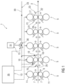
- FIG 1 shows schematically a rolling train 1 for hot rolling rolled strips 3.
- the rolling train 1 has five rolling stands 5 as an example.
- Each roll stand 5 has two work rolls 7, which are spaced apart from one another by a roll gap 9.
- each roll stand 5 has a support roll 11 for each work roll 7, which is arranged on a side of the work roll 7 facing away from the roll gap 9 and can be adjusted to the work roll 7.
- the rolling train 1 has for each work roll 7 an exemplary embodiment of a device 13 according to the invention for operating the work roll 7 during hot rolling of several Rolled strips 3 on.
- Each of these devices 13 includes a lubricating device 15, which is set up to dispense a lubricant 16 onto a roll surface 17 of the work roll 7, and a cleaning device 19, which is set up to dispense a cleaning agent 20 onto the roll surface 17 of the work roll 7.
- Each lubricating device 15 comprises at least one lubricating bar 21 with a plurality of lubricating nozzles for dispensing the lubricant 16.
- the lubricant 16 is a mixture of oil and water, for example with an oil content in the range of 1% to 5%.
- the cleaning device 19 of a device 13 comprises at least one cooling bar 22 of a cooling device 23, which is set up to dispense cooling water 24 onto the roll surface 17 of the respective work roll 7.
- Each cooling beam 22 has a plurality of cooling nozzles for dispensing the cooling water 24.
- the rolling train 1 includes an anti-peeling device 25 and a scraper 27 for each work roll 7.
- the anti-peeling device 25 is set up to apply an anti-peeling coolant 26 to the rolled strips 3 and includes at least one for this purpose Anti-peel spray bar 29 with several anti-peel nozzles.
- the anti-peeling coolant 26 cools a surface of a hot rolled strip 3 shortly before entering the roll gap 9 and thereby prevents thermal surface damage to the respective work roll 7, such as peeling off an oxide layer of the work roll 7.
- An anti-peeling coolant 26 is used, for example Cooling water used.
- Each scraper 27 for a work roll 7 can be adjusted to the roll surface 17 of the work roll 7 in order to keep cooling water 24 dispensed onto the work roll 7 away from the rolled strips 3.
- the lubricating device 15, the anti-peeling device 25 and the scraper 27, which are assigned to a work roll 7, are arranged on an inlet side of the work roll 7, from which the rolled strips 3 are fed to the roll gap 9.
- the cooling device 23 assigned to a work roll 7 is arranged on an outlet side of the work roll 7, to which the rolled strips 3 leave the roll gap 9.
- the lubricant 16 and the anti-peeling coolant 26 are therefore applied to the roll surface 17 of the work roll 7 on the inlet side of the work roll 7, and the cooling water 24 and the cleaning agent 20 are applied to the roll surface 17 of the work roll 7 on the outlet side.
- the anti-peel coolant 26 is dispensed onto the rolled strip 3, for example, in an amount of approximately 100 m 3 /h per roll stand 5 and at a pressure of approximately 3 bar.
- the cooling water 24 is applied from the cooling devices 23 to the work rolls 7, for example in an amount of approximately 1000 m 3 /h per roll stand 5 and at a pressure of approximately 5 bar to 15 bar.
- the output of lubricant 16 by the lubricating devices 15 of the roll stand 5 and the output of anti-peeling coolant 26 are adjusted by the anti-peel devices 25 of the roll stand 5 and from the cooling devices 23 of the roll stand 5, instead of the cooling water 24, the cleaning agent 20 is dispensed onto the roll surfaces 17 of the work rolls 7 of the roll stand 5.
- the temperature of the cleaning agent 20 is, for example, in a range from 20 ° C to 60 ° C.
- the cleaning agent 20 is dispensed by the cooling devices 23, for example at a pressure of approximately 5 bar.
- the concentration of the detergent in the water is, for example, between 0% and 10%, preferably between 0.5% and 5%.
- the dosage of the cleaning agent 20 for the rolling stands 5 is adjusted with at least one metering valve 30, to which the detergent from a detergent reservoir 31 and water from a cooling water supply 33 can be supplied.
- the lubricating devices 15, cooling devices 23, anti-peeling devices 25 and the at least one metering valve 30 are controlled by a control unit 35.
- This is in Figure 1 indicated by dashed arrows as an example for the upper work roll 7 of the second roll stand 5 of the rolling train 1.
- the control unit 35 also controls the further stand settings of the roll stands 5 of the work rolls 7, in particular the distances between the two work rolls 7 of each roll stand 5 and thus the sizes of the roll gaps 9 of the roll stands 5 as well as the angular speeds at which the work rolls 7 and the support rolls 11 rotate.
- This is in Figure 1 indicated by dashed arrows pointing to the support rollers 11.
- the control unit 35 is therefore a control system for the rolling mill 1.
- FIG 2 shows schematically a roll stand 5 with a second exemplary embodiment of devices 13 for operating the work rolls 7 during hot rolling of several rolled strips in a rolling train 1.
- This exemplary embodiment differs from that in Figure 1 shown embodiment essentially in that the cleaning device 19 of each device 13 has at least one separate cleaning bar 37 with several cleaning nozzles with which the cleaning agent 20 can be dispensed onto the roll surface 17 of a work roll 7.
- the cleaning nozzles are, for example, flat jet nozzles, each of which emits a jet with an opening angle of, for example, approximately 90 degrees.
- the cleaning bars 37 are arranged on the inlet side of the roll stand 5, so that the cleaning agent 20 is dispensed onto the roll surfaces 17 of the work rolls 7 on the inlet side.
- a lubricating device 15 with at least one lubricating bar 21 is also arranged for each work roll 7, with which a lubricant 16 can be dispensed onto the roll surface 17 of the work roll 7.
- two anti-peel devices 25, each with at least one anti-peel spray bar 29, are arranged on the inlet side of the roll stand 5, with which an anti-peel coolant 26 can be dispensed onto the top surface and the bottom surface of a rolled strip 7 .
- a cooling device 23 with several cooling beams 22 is arranged for each work roll 7, with which cooling water 24 can be dispensed onto the roll surface 17 of the work roll 7.
- cooling device 23 can also have cooling beams 22 arranged on the inlet side (in Figure 2 not shown). In such a case, for example, 20% to 30% of the cooling water 24 is applied to the roll surface 17 on the inlet side of the roll stand 5.
- each rolled strip 3 through a roll gap 9 of a roll stand 5, from a time t 2 at which a strip head of the rolled strip 3 has completely passed through the roll gap 9, until the strip end of the rolled strip 7 leaves the roll gap 9 from the lubricating devices 15 of the roll stand 5, the lubricant 16 is applied to the roll surfaces 17 of the work rolls 7 of the roll stand 5.
- the anti-peeling coolant 26 is dispensed onto the rolled strip 3 from the anti-peeling devices 25 of the roll stand 5 and cooling water 24 is applied to the roll surfaces 17 of the work rolls 7 of the roll stand 5 from the cooling devices 23 of the roll stand 5.
- the cleaning devices 19 are switched off, so that no cleaning agent 20 is applied to the roll surfaces 17 of the work rolls 7.
- the output of lubricant 16 by the lubricating devices 15 of the roll stand 5 and the output of anti-peel coolant 26 by the anti-peel devices 25 of the roll stand 5 are adjusted. Furthermore, during each rolling break ⁇ t, the cleaning agent 20 is dispensed from the cleaning devices 19 onto the roll surfaces 17 of the work rolls 7, and cooling water 24 is dispensed from the cooling devices 23 of the roll stand 5 onto the roll surfaces 17 of the work rolls 7 of the roll stand 5.
- the cleaning agent 20 used by the cleaning devices 19 is, for example, water or water with a detergent dissolved in the water, in particular hot water (for example water with a temperature greater than 35 ° C) or hot water with a detergent dissolved in the water, pressurized onto the roller surfaces 17 of the work rolls 7 are issued.
- the cleaning agent 20 is dispensed from the cleaning devices 19 at a pressure in the range of 2 bar to 50 bar.
- the lubricant 16 remaining on the work rolls 7 is dissolved by the cleaning agent 20 and washed off the roll surfaces 17 of the work rolls 7 by the cooling water 24 discharged from the cooling devices 23.
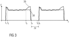
- FIG 3 illustrates the method according to the invention for operating a work roll 7 when hot rolling several rolled strips by a diagram of a rolling force F acting on rolled strips 3 in a rolling stand 5 as a function of time t in comparison to a conventional method.
- 38 denotes a force curve of the rolling force F in the method according to the invention and 39 denotes a force curve of the rolling force F in the conventional method.
- t 1 the beginning of a rolled strip 3 reaches the rolling gap 9 of the rolling stand 5, as a result of which the rolling force F increases steeply.
- a band head of the rolled strip 3 has completely passed through the roll gap 9.
- the band head for example, has a length that is twice as large as the circumference of the work roll 7, so that the band head is guided through the roll gap 9 during two revolutions of the work roll 7. From time t 2 , the lubricant 16 is dispensed onto the roll surface 17 of the work roll 7 both in the method according to the invention and in the conventional method. As a result, the rolling force F decreases in both processes compared to rolling the roll head.
- the lubrication of the roll surface 17 of the work roll 7 is set at a time t 3 at which a band foot of the rolled strip 3 reaches the roll gap 9.
- the band foot for example, has a length that is three to five times as large as the circumference of the work roll 7, so that the band foot is guided through the roll gap 9 during three to five revolutions of the work roll 7.
- lubricant 16 remaining on the roll surface 17 of the work roll 7 burns in the roll gap 9 due to the high temperature of the rolled strip 3. Since during this As long as no lubricant 16 is supplied to the roll surface 17 of the work roll 7, the friction increases between Roll surface 17 and the rolled strip 3 and thus the rolling force F from time t 3 to time t 4 again.
- the lubrication of the roll surface 17 of the work roll 7 is maintained from time t2 to time t4, so that the roll surface 17 is lubricated throughout the entire passage of the strip foot through the roll gap 9.
- a rolling break ⁇ t from the time t 4 to a time t 6 at which the beginning of the strip of the subsequent rolled strip 3 reaches the roll gap 9, there is no rolled strip 3 in the roll gap 9, so that the rolling force F disappears during the rolling break ⁇ t.
- the roll surface 17 of the work roll 7 is cleaned from the time t 4 to a time t 5 during the rolling break ⁇ t by dispensing the cleaning agent 20 onto the roll surface 17, so that at the time t 6 there is no or only very little there is little lubricant 16 on the roller surface 17.
- the lubrication of the roll surface 17 is only resumed when the strip head of the subsequent rolled strip 3 has completely passed the roll gap 9.
Landscapes
- Engineering & Computer Science (AREA)
- Mechanical Engineering (AREA)
- Metal Rolling (AREA)
Priority Applications (1)
| Application Number | Priority Date | Filing Date | Title |
|---|---|---|---|
| EP22177058.9A EP4286068A1 (fr) | 2022-06-02 | 2022-06-02 | Procédé et dispositif pour fonctionnement d'un cylindre de travail lors du laminage à chaud |
Applications Claiming Priority (1)
| Application Number | Priority Date | Filing Date | Title |
|---|---|---|---|
| EP22177058.9A EP4286068A1 (fr) | 2022-06-02 | 2022-06-02 | Procédé et dispositif pour fonctionnement d'un cylindre de travail lors du laminage à chaud |
Publications (1)
| Publication Number | Publication Date |
|---|---|
| EP4286068A1 true EP4286068A1 (fr) | 2023-12-06 |
Family
ID=81878182
Family Applications (1)
| Application Number | Title | Priority Date | Filing Date |
|---|---|---|---|
| EP22177058.9A Withdrawn EP4286068A1 (fr) | 2022-06-02 | 2022-06-02 | Procédé et dispositif pour fonctionnement d'un cylindre de travail lors du laminage à chaud |
Country Status (1)
| Country | Link |
|---|---|
| EP (1) | EP4286068A1 (fr) |
Citations (5)
| Publication number | Priority date | Publication date | Assignee | Title |
|---|---|---|---|---|
| JP2002178011A (ja) * | 2000-12-06 | 2002-06-25 | Sumitomo Metal Ind Ltd | 鋼板の熱間潤滑圧延方法およびその装置 |
| WO2005120739A1 (fr) * | 2004-06-09 | 2005-12-22 | Sms Demag Ag | Procede et cage de laminoir pour laminer a froid une matiere metallique a laminer, en particulier un feuillard, ladite cage etant pourvue de buses destinees a pulveriser des agents de traitement gazeux ou liquides |
| JP2011132302A (ja) * | 2009-12-22 | 2011-07-07 | Kao Corp | 圧延機廻り用洗浄剤組成物 |
| EP2554283A1 (fr) * | 2010-03-31 | 2013-02-06 | Nippon Steel & Sumitomo Metal Corporation | Procédé et dispositif de production de tôle d'acier laminée à chaud |
| WO2013113441A1 (fr) * | 2012-02-01 | 2013-08-08 | Siemens Aktiengesellschaft | Dispositif de nettoyage et procédé permettant d'éliminer un lubrifiant des cylindres d'une cage de laminoir |
-
2022
- 2022-06-02 EP EP22177058.9A patent/EP4286068A1/fr not_active Withdrawn
Patent Citations (5)
| Publication number | Priority date | Publication date | Assignee | Title |
|---|---|---|---|---|
| JP2002178011A (ja) * | 2000-12-06 | 2002-06-25 | Sumitomo Metal Ind Ltd | 鋼板の熱間潤滑圧延方法およびその装置 |
| WO2005120739A1 (fr) * | 2004-06-09 | 2005-12-22 | Sms Demag Ag | Procede et cage de laminoir pour laminer a froid une matiere metallique a laminer, en particulier un feuillard, ladite cage etant pourvue de buses destinees a pulveriser des agents de traitement gazeux ou liquides |
| JP2011132302A (ja) * | 2009-12-22 | 2011-07-07 | Kao Corp | 圧延機廻り用洗浄剤組成物 |
| EP2554283A1 (fr) * | 2010-03-31 | 2013-02-06 | Nippon Steel & Sumitomo Metal Corporation | Procédé et dispositif de production de tôle d'acier laminée à chaud |
| WO2013113441A1 (fr) * | 2012-02-01 | 2013-08-08 | Siemens Aktiengesellschaft | Dispositif de nettoyage et procédé permettant d'éliminer un lubrifiant des cylindres d'une cage de laminoir |
Similar Documents
| Publication | Publication Date | Title |
|---|---|---|
| EP2750813B2 (fr) | Laminoir réversible et procédé de fonctionnement pour un laminoir réversible | |
| EP2794137B1 (fr) | Dispositif de nettoyage et procédé de suppression d'un lubrifiant à partir des cylindres d'une cage de laminoir | |
| WO2018073086A1 (fr) | Refroidissement d'un cylindre d'une cage de laminoir | |
| EP1900449B1 (fr) | Poutre de pulvérisation d'une installation de décalaminage hydraulique et procédé de fonctionnement d'une telle poutre de pulvérisation | |
| EP3733317B1 (fr) | Laminage d'un laminé | |
| WO2010149351A1 (fr) | Dispositif et procédé pour couler horizontalement un feuillard métallique | |
| DE10157742C1 (de) | Verfahren zum Betreiben eines Streckreduzierwalzwerks und Streckreduzierwalzwerk | |
| EP3691805B1 (fr) | Laminage d'un laminé | |
| EP4286068A1 (fr) | Procédé et dispositif pour fonctionnement d'un cylindre de travail lors du laminage à chaud | |
| EP3670011B1 (fr) | Refroidissement de la bande métallique dans une cage de laminoir | |
| EP3941655B1 (fr) | Installation et procédé pour fabriquer un feuillard à chaud métallique | |
| WO2017186910A1 (fr) | Procédé pour laminer une matière à laminer | |
| DE102023104550A1 (de) | Vorrichtung und Verfahren zum Schmieren einer Arbeitswalze eines Warmwalzgerüsts | |
| EP1704000B1 (fr) | Procede de lubrification de produits a laminer | |
| EP1802406B2 (fr) | Procede et dispositif pour nettoyer des cylindres | |
| EP3419778A1 (fr) | Ensemble de rangées de buses et champ de buses destinés à être montés dans des fentes situées entre deux rouleaux de corset de guidage | |
| DE19850738A1 (de) | Betriebsverfahren für ein Walzgerüst einer Walzstraße | |
| EP3698895A1 (fr) | Installation et procédé de texturisation de la surface d'une bande métallique | |
| EP3421148B1 (fr) | Nettoyage de laminés lors de leur laminage à froid | |
| EP4501480A1 (fr) | Procédé et système pour l'application d'un lubrifiant lors du laminage à froid d'un produit à laminer dans une cage de laminoir | |
| EP4045204B1 (fr) | Dispositif de refroidissement à rayonnement de refroidissement pourvu de section transversale creuse | |
| EP1516683A1 (fr) | Dispositif pour refroidir et/ou lubrifier des cylindres de laminoirs pour feuillards à froid, notamment feuillards fins et feuilles minces | |
| EP1579928B1 (fr) | Procédé d'enlèvement de calamine ou de rouille d'un produit métallique déformable | |
| DE19935780A1 (de) | Verfahren und Einrichtung zum Kühlen eines Metallbandes | |
| DE102021213566A1 (de) | Verfahren zum Betreiben einer Walzstraße |
Legal Events
| Date | Code | Title | Description |
|---|---|---|---|
| PUAI | Public reference made under article 153(3) epc to a published international application that has entered the european phase |
Free format text: ORIGINAL CODE: 0009012 |
|
| STAA | Information on the status of an ep patent application or granted ep patent |
Free format text: STATUS: THE APPLICATION HAS BEEN PUBLISHED |
|
| AK | Designated contracting states |
Kind code of ref document: A1 Designated state(s): AL AT BE BG CH CY CZ DE DK EE ES FI FR GB GR HR HU IE IS IT LI LT LU LV MC MK MT NL NO PL PT RO RS SE SI SK SM TR |
|
| STAA | Information on the status of an ep patent application or granted ep patent |
Free format text: STATUS: THE APPLICATION IS DEEMED TO BE WITHDRAWN |
|
| 18D | Application deemed to be withdrawn |
Effective date: 20240607 |
|
| RAP3 | Party data changed (applicant data changed or rights of an application transferred) |
Owner name: PRIMETALS TECHNOLOGIES AUSTRIA GMBH |