EP4286080A2 - Ensemble de serrage servant de porte-outil pour un outil - Google Patents
Ensemble de serrage servant de porte-outil pour un outil Download PDFInfo
- Publication number
- EP4286080A2 EP4286080A2 EP23198307.3A EP23198307A EP4286080A2 EP 4286080 A2 EP4286080 A2 EP 4286080A2 EP 23198307 A EP23198307 A EP 23198307A EP 4286080 A2 EP4286080 A2 EP 4286080A2
- Authority
- EP
- European Patent Office
- Prior art keywords
- peeling
- clamping
- clamping assembly
- carrier
- central axis
- Prior art date
- Legal status (The legal status is an assumption and is not a legal conclusion. Google has not performed a legal analysis and makes no representation as to the accuracy of the status listed.)
- Pending
Links
Images


Classifications
-
- B—PERFORMING OPERATIONS; TRANSPORTING
- B26—HAND CUTTING TOOLS; CUTTING; SEVERING
- B26D—CUTTING; DETAILS COMMON TO MACHINES FOR PERFORATING, PUNCHING, CUTTING-OUT, STAMPING-OUT OR SEVERING
- B26D3/00—Cutting work characterised by the nature of the cut made; Apparatus therefor
- B26D3/16—Cutting rods or tubes transversely
- B26D3/164—Cutting rods or tubes transversely characterised by means for supporting the tube from the inside
-
- B—PERFORMING OPERATIONS; TRANSPORTING
- B23—MACHINE TOOLS; METAL-WORKING NOT OTHERWISE PROVIDED FOR
- B23B—TURNING; BORING
- B23B5/00—Turning-machines or devices specially adapted for particular work; Accessories specially adapted therefor
- B23B5/16—Turning-machines or devices specially adapted for particular work; Accessories specially adapted therefor for bevelling, chamfering, or deburring the ends of bars or tubes
- B23B5/161—Devices attached to the workpiece
- B23B5/162—Devices attached to the workpiece with an internal clamping device
-
- B—PERFORMING OPERATIONS; TRANSPORTING
- B23—MACHINE TOOLS; METAL-WORKING NOT OTHERWISE PROVIDED FOR
- B23B—TURNING; BORING
- B23B2220/00—Details of turning, boring or drilling processes
- B23B2220/40—Peeling
-
- B—PERFORMING OPERATIONS; TRANSPORTING
- B23—MACHINE TOOLS; METAL-WORKING NOT OTHERWISE PROVIDED FOR
- B23B—TURNING; BORING
- B23B2260/00—Details of constructional elements
- B23B2260/03—Clamps
-
- B—PERFORMING OPERATIONS; TRANSPORTING
- B23—MACHINE TOOLS; METAL-WORKING NOT OTHERWISE PROVIDED FOR
- B23B—TURNING; BORING
- B23B2270/00—Details of turning, boring or drilling machines, processes or tools not otherwise provided for
- B23B2270/02—Use of a particular power source
- B23B2270/025—Hydraulics
-
- B—PERFORMING OPERATIONS; TRANSPORTING
- B23—MACHINE TOOLS; METAL-WORKING NOT OTHERWISE PROVIDED FOR
- B23B—TURNING; BORING
- B23B2270/00—Details of turning, boring or drilling machines, processes or tools not otherwise provided for
- B23B2270/08—Clamping mechanisms; Provisions for clamping
Definitions
- the present invention relates to a peeling device for at least partially removing the surface of an at least approximately tubular body and to a clamping assembly as a tool carrier for a tool, such as a peeling knife arrangement of a peeling device, for processing an approximately tubular body.
- the present invention relates to a peeling device for at least partially removing the surface of an at least approximately tubular body with a central axis, in particular a plastic pipe, with a clamping assembly having a central axis and at least one clamping element for clamping the peeling device on the tubular body, wherein in the assembled state, the central axis of the clamping assembly coincides at least approximately with the central axis of the tubular body, and with a peeling assembly comprising a peeling arm unit, a peeling knife arrangement arranged at a first end of the peeling arm unit and a peeling arm carrier which connects the clamping assembly to the peeling arm unit, the peeling arm unit having a second end is connected to the peeling arm carrier in such a way that the peeling arm unit and the central axis of the clamping assembly lie in a common plane, the peeling knife arrangement having a peeling knife.
- the present invention further relates to a clamping assembly as a tool carrier for a tool, such as a peeling knife arrangement of a peeling device, for processing an approximately tubular body with a central axis, in particular a plastic tube.
- the clamping assembly has a central axis, a carrier shaft arranged coaxially to the central axis of the clamping assembly and at least one clamping device arranged on the carrier shaft and directed essentially radially outwards.
- plastic pipes for this purpose.
- the plastic pipes are connected at their ends to one another or to other shaped parts, such as T-pieces or cross pieces, for example via heating coil fittings by means of heating coil welding.
- the outer surfaces of the plastic pipes are slightly removed before the actual welding in those places where welding with a molded part or the like is to take place.
- plastic pipes or their ends are not always exactly cylindrical, but can have ovalities.
- the surface of such plastic pipes can have further unevenness, such as scratches or grooves, or chemical changes, such as oxidation or contamination, which can prevent a secure and/or media-tight connection between the tubular body and the fitting placed on it, or at least the quality of this affect connection. It is therefore customary to process the sections of the tubular body on which such a shaped piece is to be placed using a peeling device in order to eliminate such unevenness or changes in the tubular body surface.
- a peeling device for scraping the outer surface of a plastic pipe which is clamped by means of clamping arms in one end of the plastic pipe or tubular body to be processed.
- An arm which carries a scraper blade at its free end, is aligned parallel to the surface of the tubular body so that the scraper blade rests on the tubular body.
- the other end of the arm is connected to a drive spindle so that the arm can be driven to rotate around the tubular body, with the scraper blade removing material from the surface of the tubular body.
- peeling devices for removing material from the surface of a plastic pipe are essentially C-shaped and have a scraper blade directed towards the inside.
- a peeling device is from the EP patent application 1 160 035 known.
- the scraper blade In addition to the scraper blade, it has rollers on its inside, by means of which the peeling device can roll along the surface of the tubular body to be processed, while the scraper blade removes material from the pipe surface.
- a peeling device for at least partially removing the surface of an at least approximately tubular body with a central axis, in particular a plastic pipe, with a clamping assembly having a central axis and at least one clamping element for clamping the peeling device on the tubular body, the central axis in the assembled state the clamping assembly at least approximately coincides with the central axis of the tubular body, and with a peeling assembly comprising a peeling arm unit, a peeling knife arrangement arranged at a first end of the peeling arm unit and a peeling arm carrier with a first end and a second end which connects the clamping assembly to the peeling arm unit, wherein the peeling arm unit is connected at a second end to the peeling arm carrier in such a way that the peeling arm unit and the central axis of the clamping assembly lie in a common plane in the assembled state.
- the peeling knife arrangement has a peeling knife which is arranged at a first end of the peeling arm unit.
- the peeling arm unit is connected with its first and second ends to the peeling knife arrangement and the peeling arm carrier and can be pivoted in the common plane with the central axis of the clamping assembly so that the knife carriage maintains its alignment with the central axis of the clamping assembly in every pivoting position of the peeling arm unit .
- This can ensure that a paring knife of a paring knife arrangement maintains its alignment with the tubular body to be machined at every processing time, whereby uniform material removal and a high surface quality can be guaranteed.
- the paring knife arrangement can be designed in different ways.
- the peeling knife arrangement has a knife carriage with a peeling knife arranged therein or on it, which is arranged at the end of the peeling arm unit. Such a knife carriage can ensure precise guidance of the paring knife.
- the pivot axes can be implemented in different ways. In one embodiment it can be provided that the pivot axes are formed by hinge pins which are accommodated in corresponding bores.
- the peeling arm unit has at least mutually parallel first and second peeling arm elements with first and second ends, which are pivotally connected to the peeling knife arrangement and the peeling arm carrier, with oriented perpendicular to the common plane of the peeling arm unit and the central axis of the clamping assembly Swivel axes.
- This configuration enables the peeling knife arrangement or the knife carriage to compensate for ovalities of the tubular body to be processed and at the same time to adapt to the reduced or reducing diameter of the processed tubular body.
- the alignment of the paring knife arrangement or the knife carriage, and thus the alignment of the paring knife, to the tubular body axis is retained.
- the peeling arm elements are arranged one above the other in the radial direction, relative to the central axis of the clamping assembly, whereby your movement of the knife carriage exclusively in the common direction Level of the peeling arm unit and the central axis of the clamping assembly can be ensured.
- the distances between the pivot axes in the radial direction, relative to the central axis of the clamping assembly, and in the axial direction, relative to the central axis of the clamping assembly are the same size, so that the pivot axes are in the common plane of the peeling arm unit and the central axis of the clamping assembly form the corner points of a parallelogram. This achieves the desired movement of the paring knife arrangement relative to the tubular body.
- the distances between the pivot axes are the same size in the radial direction, relative to the central axis of the clamping assembly, but are different in the axial direction, relative to the central axis of the clamping assembly.
- a desired movement of the peeling knife arrangement relative to the tubular body can thereby be achieved.
- At least one of the bores attached to one of the second ends of the peeling arm elements for receiving the hinge pins forming the pivot axes has a larger cross section that deviates from the cross section of the hinge pin. This achieves additional pivotability of the peeling knife arrangement in order to further improve the alignment of the peeling knife with respect to the tubular body to be processed.
- the cross section of the hole receiving the hinge pin can, for example, have the shape of an elongated hole, or be a hole with a larger diameter than the diameter of the hinge pin.
- the cross section of the bore can also have any other shape, as long as this allows additional pivoting of the peeling knife arrangement to be achieved.
- the elongated hole can be designed differently.
- the elongated hole is designed in the shape of an arc or part of a circle.
- the diameter of one of the bores is larger than the diameter of the hinge pin accommodated therein.
- the tilt angle that can be achieved through this additional tiltability of the peeling knife arrangement can be between 0.5° to 20°, preferably 2.5° to 12.5°, more preferably 3° and 7°, particularly preferably approximately 5°.
- a support element is arranged between the second ends of the peeling arm elements and the peeling knife arrangement.
- a carrier element enables a targeted alignment of the peeling knife arrangement to the peeling arm elements.
- the peeling knife arrangement includes the peeling knife and the associated fastening elements and, if necessary, alignment elements, which are arranged directly on the carrier element. If the peeling knife arrangement includes a knife carriage, this is attached to the support element.
- the second ends of the first and second peeling arm elements are at least approximately C-shaped and at least partially surround the carrier element. This configuration enables the hinge pins to be attached in the area of the C-shaped ends, which, in addition to the desired pivotability, also enables the peeling arm elements to be guided in the pivoting plane.
- first end of the first peeling arm element is at least approximately C-shaped and at least partially surrounds the peeling arm carrier in order to ensure guidance in the pivoting plane of the peeling arm unit here too.
- the first end of the second peeling arm element can have an opening into which the peeling arm carrier projects with its first end. This ensures the pivotability and guidance of the second peeling arm element in its pivoting plane.
- the carrier element is arranged laterally next to the second ends of the first and second peeling arm elements.
- first and second peeling arm elements For the pivotable arrangement of the first and second peeling arm elements on the peeling arm carrier, it is also possible for the first ends of the first and second peeling arm elements to be received in a recess at the second end of the peeling arm carrier and to be pivotably held in this by means of the hinge bolts.
- the peeling device comprises a force application unit which exerts a deflection force on the peeling arm unit for reversibly prestressing the peeling arm unit in a peeling position, in a direction in the common plane of the peeling arm unit and the central axis of the clamping assembly.
- the knife carriage is always in contact with the pipe surface.
- the peeling knife is prevented from lifting off the pipe surface, so that material can be removed, for example to reduce or eliminate scratches or grooves in the pipe surface.
- the paring knife can be pretensioned in different ways.
- the force application unit has at least one elastic element, such as a spring, for generating the deflection force.
- An elastic element represents a technically simple way to generate a preload.
- the force application unit has an adjustment mechanism for adjusting the level of the deflection force. By adjusting the level of the deflection force, it can be ensured that the knife carriage sits on the pipe surface even with larger ovalities of the tubular body.
- the adjustment mechanism can be operated in different ways.
- the adjustment mechanism comprises a tensioning lever.
- other actuating elements can also be used, such as adjusting screws or the like.
- the clamping lever has an eccentric cam and can be pivoted about an axis of rotation in such a way that the elastic element is compressed, whereby the deflection force is generated, or is relieved.
- the adjustment mechanism has a pressure plate which can be reversibly displaced along the peeling arm support, the elastic element being arranged between the pressure plate and a section of the peeling arm unit. By moving the pressure plate relative to the section of the peeling arm unit, the elastic element located therebetween can be put under tension in order to set a desired preload with which the knife carriage rests on the pipe surface.
- the pressure plate can be moved directly by hand by the operator along the peeling arm carrier. This preferably happens when the peeling arm unit is in an unloaded state. The pressure plate is adjusted and clamped in a powerless state. By then aligning the peeling arm unit into the peeling position, the pretension can be set to the desired value or, if necessary, increased further.
- a lever with an eccentric mechanism such as the tensioning lever with its eccentric cam, can be provided in order to put the elastic element under tension.
- the eccentric mechanism can be designed in such a way that when pivoting about the axis of rotation it acts on the pressure plate, which can be reversibly displaced along the peeling arm carrier.
- the adjusting mechanism for adjusting the level of the deflection force comprises an adjusting screw mechanism.
- This can include a hand-operated adjusting screw, which further simplifies the operation of the adjustment mechanism.
- a stopper or stop which limits the deflection of the peeling arm unit.
- an elastic element can also be provided, which is compressed into a state predetermined by the stop, which results in a fixed value of a deflection force.
- a stop can be realized in the form of a screw, which is arranged so that the peeling arm unit or an element thereof comes into contact with the screw head.
- Other elements such as a pin or a bolt, are also suitable as a stop.
- peeling knife arranged in the knife carriage is also biased in a direction perpendicular to the central axis of the clamping assembly, this can ensure uniform material removal.
- the knife carriage has at least two rollers arranged at least approximately axially parallel to the central axis of the clamping assembly, which rest on the surface of the tubular body in the assembled state of the peeling device.
- the rollers or wheels not only enable the knife carriage to be guided smoothly and evenly over the pipe surface, but also keep the knife carriage at a constant distance from the pipe surface.
- the distance of the peeling arm unit to the central axis of the clamping assembly is adjustable.
- the distance between the peeling arm unit and the central axis of the clamping assembly can be adjusted in different ways.
- An embodiment is preferred in which the peeling arm carrier can be displaced along the clamping assembly and at least approximately perpendicular to its central axis.
- the peeling arm unit is designed to be displaceable along the peeling arm carrier and to be correspondingly fixable to it in the different positions.
- the position of the peeling arm carrier is adjustable along the central axis of the clamping assembly. This allows the pipe surface to be processed in the axial direction to a desired length without releasing the tension of the peeling device on the tubular body.
- the position of the peeling arm carrier along the central axis of the clamping assembly can be changed step by step, for example after each revolution of the peeling arm unit around the tubular body, or continuously.
- An adjustment mechanism provided for this purpose can include, for example, a clamping device for the peeling arm carrier on the central axis of the clamping assembly, or a spindle mechanism by means of which the peeling arm carrier, and thus the peeling assembly, is displaced a certain distance along the central axis of the clamping device with each revolution around the tubular body .
- the clamping assembly may comprise only one clamping element. But in order to secure the peeling device in a precise position, preferably coaxially, it is provided that the clamping assembly has more than one clamping element, preferably three clamping elements, preferably in the form of clamping scissors.
- the clamping elements are arranged at the same angular pitch to one another in order to support central attachment of the clamping assembly in the tubular body. If three clamping elements are provided, they are arranged at an angle of 120° to one another.
- a holding element is arranged in the immediate vicinity of the central axis of the clamping assembly and between two adjacent clamping elements.
- a holding element can, for example, be designed as a handle in the form of a metal rod, or be formed by a suitable webbing or a belt loop, whereby the holding element should be attached to the tensioning assembly in such a way that the function of the tensioning assemblies is not impaired.
- a clamping assembly is proposed as a tool carrier for a tool, such as a peeling knife arrangement of a peeling device, for processing an approximately tubular body with a central axis, in particular a plastic tube.
- the tool carrier or the clamping assembly has a central axis, a carrier shaft arranged coaxially to the central axis of the clamping assembly and at least one clamping device arranged on the carrier shaft and directed essentially radially outwards.
- an actuation mechanism for actuating the at least one clamping device is arranged on the carrier shaft, for reversibly clamping the clamping assembly in the tubular body coaxially to its central axis. This enables a compact design and easy operation of the tool carrier or clamping assembly.
- the clamping assembly according to the invention is suitable as a tool carrier for different types of tools intended for machining a tubular body or the like Tools that are placed in a specific orientation to the tubular body.
- the clamping assembly according to the invention can be arranged coaxially to the central axis of the tubular body to be machined, and preferably in this. This is particularly advantageous if an at least approximately circular movement is to be carried out with respect to the central axis of the tubular body, such as a peeling tool, a pipe cutter, a thread cutter or the like.
- the at least one clamping device comprises at least one clamping scissor with at least two scissor elements that are articulated to one another, as well as at least one clamping element displaceably arranged on the support shaft, with which one of the at least two scissor elements of the at least one clamping scissors is articulated, and for actuating the clamping device by the Actuating mechanism is reversibly displaceable on the carrier shaft.
- the carrier wave can be designed differently. It can be provided as a solid shaft or as a hollow shaft. If the carrier shaft is designed as a hollow shaft, it is possible, for example, to guide a spindle, such as a threaded spindle, through this hollow shaft, to which the machining tool can be attached and held rotatable about the central axis of the clamping assembly.
- a spindle such as a threaded spindle
- the actuating mechanism comprises a threaded connection or threaded engagement between the carrier shaft and the at least one clamping element and an actuating element. It can be provided that the carrier shaft has an external thread that interacts with an internal thread of the at least one clamping element.
- the actuating element can be designed in the form of a nut or a lever, so that the actuating mechanism can be operated in a simple manner, for example with a wrench or by hand.
- a motor drive for this actuation mechanism is also conceivable.
- the actuating mechanism can comprise at least one piston-cylinder mechanism arranged coaxially on the carrier shaft, which cooperates with the at least one clamping element. This further simplifies the operation of the actuation mechanism.
- an annular cylinder space is formed between the carrier shaft and a cylinder sleeve arranged coaxially on the carrier shaft and in which an annular piston is arranged.
- the cylinder sleeve is reversibly displaceable on the carrier shaft by the actuation mechanism.
- the at least one clamping element is connected to the cylinder sleeve and is reversibly displaced on the carrier shaft by this.
- the cylinder sleeve firmly on the carrier shaft, so that the annular piston can be displaced in the annular cylinder space.
- the annular piston is connected to the at least one clamping element in order to displace it on the carrier shaft.
- the at least one piston-cylinder mechanism is connected to an external fluid source.
- a fluid source can be a hydraulic or pneumatic pump that pumps a corresponding fluid, such as hydraulic oil or air, into the piston-cylinder mechanism.
- the clamping assembly has a second clamping element which is displaceably arranged on the support shaft and which is articulated to the second of the at least two scissor elements of the clamping scissors, and a further piston-cylinder connected to the second clamping element mechanism includes.
- This further piston-cylinder mechanism preferably corresponds in structure to the first piston-cylinder mechanism and can be connected to the same fluid source. It is also possible to control both piston-cylinder mechanisms separately or to control the piston-cylinder mechanisms synchronously.
- the actuation mechanism has an integrated drive mechanism, whereby a particularly compact structure and further simplified operation of the clamping assembly is achieved.
- the integrated drive mechanism can also have an integrated fluid reservoir for receiving a fluid, such as hydraulic oil. This makes the clamping assembly independent of an external fluid source or a fluid supply.
- the fluid reservoir can be implemented in different ways. In the simplest case it is a corresponding container that can be attached to the carrier shaft, for example.
- the clamping assembly can be provided with a further cylinder sleeve arranged coaxially on the cylinder sleeve to form an integrated fluid reservoir between the cylinder sleeve and the further cylinder sleeve.
- the further cylinder sleeve for forming the fluid reservoir can be provided as a separate element.
- it is provided that it has a connection element arranged coaxially on the carrier shaft, which, in addition to other elements, also includes the further cylinder sleeve. This achieves a high degree of integration and reliable operation of the clamping assembly according to the invention.
- the clamping assembly can include an integrated pump mechanism for transferring the fluid from the fluid reservoir into the cylinder space of the piston-cylinder mechanism with a pump cylinder integrated in the further cylinder sleeve and a pump piston guided therein.
- the drive of the integrated pump mechanism can be designed differently, for example in the form of an electric drive.
- the integrated pump mechanism includes a lever for manually operating the pump mechanism.
- Fig. 1 shows a schematic perspective view of a first exemplary embodiment of a peeling device S according to the present invention.
- the peeling device S in the following version Fig. 1 comprises a clamping assembly 10 with a central axis MS, a peeling assembly 20 with a peeling arm unit 30, a peeling knife arrangement 40, a force application unit 50, and a peeling arm carrier 60.
- the peeling device S is attached to a tubular body R, the surface material of which is at least partially different from the in Fig. 1 must be peeled off or removed from the front side that can be seen.
- the clamping assembly 10 used to fix the peeling assembly 20 on the tubular body R comprises a carrier shaft in the form of a hollow shaft or carrier sleeve 12, a shaft in the form of an in Fig. 1 horizontally aligned threaded spindle 16, on which the carrier sleeve 12 is arranged, and which extends coaxially to the central axis MS of the clamping assembly 10.
- the carrier sleeve 12 points at its in Fig. 1 left end has a first flange 13 which extends radially outwards from the carrier sleeve 12.
- the clamping scissors 14 each comprise two scissor elements 14a, 14b that are articulated to one another, with one end of the scissor elements 14a being articulated to the carrier sleeve 12 via the first flange 13, and the scissor elements 14b having their corresponding ends connected to one another second flange 13 (cf. Fig. 6 ) or a comparable element are articulated.
- This second flange 13 is preferably arranged on the carrier sleeve 12 so that it can be moved at least axially.
- the clamping scissors 14 By moving the second flange 13 relative to the first flange 13 on the carrier sleeve 12, the clamping scissors 14 lengthen or shorten, as described in connection with Fig. 6 is explained. As a result, the clamping assembly 10 inserted into the tubular body R can be clamped in the tubular body R or released from it and removed in a manner known per se.
- the central axis of the support sleeve 12 is aligned coaxially with the central axis MR of the tubular body or the tube R.
- FIG. 1 Support or retaining strap, not shown, which is attached between the two flanges 13, can facilitate the handling of the clamping assembly 10 when clamping it into the tubular body R. It enables precise positioning of the clamping assembly 10 in the tubular body R, and reduces the risk of crushing during the clamping and releasing process.
- the first flange 13 is axially fixed, but is held rotatably on the carrier sleeve 12 about the central axis MS of the clamping assembly 10.
- An on in Fig. 1 Clamping element in the form of a nut 18 attached to the left end of the carrier sleeve 12 is firmly connected to the carrier sleeve 12.
- the in Fig. 1 Invisible second flange 13 is attached to the right end of the carrier sleeve 12 in an axially displaceable manner.
- the support sleeve 12 has an external thread 12a in the area of its right end, onto which the second flange 13 can be screwed using a corresponding internal thread.
- the carrier sleeve 12 By turning the nut 18, the carrier sleeve 12 also rotates about its central axis or the central axis MS of the clamping assembly 10.
- the second flange 13 moves reversibly in the axial direction along the carrier sleeve 12 towards the first flange 13, with the clamping scissors 14 opposing the inner pipe wall can be tightened or released from it (cf. Fig. 6 ).
- the peeling arm carrier 60 is attached to the left end 16a of the threaded spindle 16.
- the peeling arm carrier 60 is essentially rod-shaped and has an approximately square cross-sectional profile in the exemplary embodiments shown. One pointing the way from the threaded spindle 16 in the assembled state
- the elongated hole 66 provided on the side of the peeling arm carrier 60 extends from an area on which in Fig. 1 lower first end 62 of the peeling arm carrier 60 in the direction of the second end 64 approximately up to its middle, and perpendicular to the longitudinal extent of the peeling arm carrier 60 through it.
- the peeling arm carrier 60 is releasably attached to the left end 16a of the threaded spindle 16 by means of a fastening element 68 inserted through the elongated hole 66, such as a screw.
- the peeling arm carrier 60 is aligned perpendicular to the threaded spindle 16, that is, it is in Fig. 1 vertically aligned.
- the peeling arm carrier 60 is formed by a hollow profile, there can be a fastening element in its interior, such as a sliding nut, a sliding block or the like, by means of which the peeling arm carrier 60 can be fastened to the threaded spindle 16.
- the threaded spindle 16 can extend through the elongated hole 66.
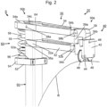
- Fig. 2 shows an enlarged perspective view.
- the peeling assembly 20 includes the peeling arm unit 30, the peeling knife arrangement 40 and the force application unit 50.
- the peeling arm unit 30 has two parallel and spaced apart from each other and in Fig. 1 horizontally aligned first and second peeling arm elements 32, 34 each having first and second ends 32a, 34a; 32b, 34b.
- the peeling arm elements 32, 34 lie in the common plane of the peeling arm unit 30 and the central axis MS of the clamping assembly 10, that is, they are arranged one above the other in the radial direction in relation to the central axis MS of the clamping assembly 10.
- the first ends 32a, 34a of the peeling arm elements 32, 34 are held in an articulated manner in the area of the second end 64 of the peeling arm carrier 60 via hinge bolts 36a, 38a.
- the hinge pins 36a, 38a are aligned transversely to the longitudinal extent of the peeling arm carrier 60 and perpendicular to the central axis MS of the clamping assembly 10.
- the peeling arm elements 32, 34 have a substantially rectangular cross section, in an area between their first and second ends 32a, 34a; 32b, 34b extending recesses which reduce the weight of the peeling arm elements 32, 34.
- the peeling arm elements 32, 34 can also have any other suitable cross section, such as a round, oval or triangular cross section.
- the second ends 32b, 34b of the peeling arm elements 32, 34 are articulated via hinge bolts 36b, 38b to a first leg 39a of a substantially C-shaped support element 39.
- the C-shaped support element 39 is aligned so that the letter "C” it forms on the head with reference to Fig. 2 , downward-pointing free legs 39a, 39b.
- the hinge pins 36b, 38b are also aligned transversely to the longitudinal extent of the peeling arm carrier 60 and perpendicular to the central axis MS of the clamping assembly 10.
- the respective radial relative to the central axis MS of the clamping assembly 10, ie the corresponding one Figures 1 to 5 vertical distance between the hinge pins 36a, 38a and the hinge pins 36b, 38b is identical. Furthermore, the distances between the hinge pins 36a, 36b of the peeling arm element 32 and between the hinge pins 38a, 38b of the peeling arm element 34 in the axial direction are also related to the central axis MS of the clamping assembly 10, ie the corresponding Figures 1 to 5 in the horizontal direction, the same size, so that between the hinge pins 36a, 36b; 38a, 38b lying sections of the peeling arm elements 32, 34 with the corresponding sections of the peeling arm carrier 60 and the leg 39a of the carrier element 39 facing them form a parallelogram, in the corner points of which the hinge pins 36a, 36b; 38a, 38b lie.
- the alignment of the peeling knife arrangement 40 to the peeling arm carrier 60, and thus also the orientation of the peeling knife arrangement 40 to the tubular body R, remains the same in every pivoting position of the peeling arm unit 30 in the circumferential direction of the tubular body R.
- the pairs of hinge pins 36a, 38a; 36b, 38b each aligned radially to the central axis MS of the clamping assembly 10
- Line arranged accordingly Fig. 2 is aligned perpendicular to the horizontally extending central axis MS of the clamping assembly 10.
- a deviation from this vertical alignment is possible, at least within limits.
- the paring knife arrangement 40 is attached to the second leg 39b of the essentially C-shaped support element 39.
- the paring knife arrangement 40 has a substantially cuboid knife carriage 42, in which a paring knife 44 is arranged such that it protrudes or protrudes from the knife carriage 42 on the side facing the central axis MS of the clamping assembly 10.
- the knife carriage 42 also has two rollers or wheels 46 arranged one behind the other in relation to the circumferential direction of the tubular body R, the axes of which are aligned parallel to one another and parallel to the central axis MS of the clamping assembly 10 when attached to a tubular body R.
- the rollers 46 protrude from the side of the knife carriage 42 facing the central axis MS of the clamping assembly 10.
- the rollers 46 When attached to a tubular body R, the rollers 46 stand on the surface of the tubular body R, so that the knife carriage 42 can roll on the tubular body R.
- the paring knife 44 which protrudes from the knife carriage 42 in the direction of the tubular body R, is biased in the direction of the central axis MR of the tubular body R by a spring element, not shown, so that it rests on the tubular body R under this bias and into the material can penetrate on the outer peripheral surface of the tubular body R.
- the knife carriage 42 is connected to the second leg 39b of the carrier element 39 via a hinge pin 48 and can be pivoted about the carrier element 39.
- the hinge pin 48 is aligned parallel to the central axis MS of the clamping assembly 10. This means that the knife carriage 42 can possibly Surface defects, such as flattenings, present on the surface of the tubular body R follow or compensate for them without departing from it.
- the first end 32a of the first peeling arm element 32 facing the peeling arm carrier 60 is C-shaped and thus partially surrounds the peeling arm carrier 60.
- the first end 34a of the second peeling arm element 34 has an opening 34c, the cross section of which at least approximately corresponds to the cross section of the peeling arm carrier 60, which extends or engages into this opening 34c, but can also pass through it completely.
- the first peeling arm element 32 ends with its first end 32a on the peeling arm carrier 60, whereas the second peeling arm element 34 ends with its first end 34a over the peeling arm carrier 60 in Fig. 2 protrudes to the left.
- a pressure plate 52 is arranged on the peeling arm carrier 60, which is shown in the illustration Figures 1 and 2 is at least approximately horizontally aligned.
- the pressure plate 52 has an opening 52a, the cross section of which essentially corresponds to the cross section of the peeling arm carrier 60, which extends at least approximately vertically through this opening 52a.
- the opening 52a is slightly larger than the cross section of the peeling arm carrier 60, so that the pressure plate 52 can be moved along the peeling arm carrier 60.
- the opening 52a is arranged in the section of the pressure plate 52 facing the peeling knife arrangement 40, so that the pressure plate 52 extends essentially to the side of the peeling arm carrier 60 opposite the peeling knife arrangement 40, and here forms a pressure plate section 54.
- An elastic element 58 forming a force-applying element is arranged between the first end 34a of the peeling arm element 34 and the pressure plate section 54 of the pressure plate 52.
- Essentially cylindrical guide or securing elements 56 are attached to the mutually facing surfaces of the first end 34a of the peeling arm element 34 and the pressure plate section 54 of the pressure plate 52, which secure the elastic element 54 in its position.
- the opening 52a in the pressure plate 52 is designed in such a way that the pressure plate 52 is tilted in a desired position on the peeling arm carrier 60 under the influence of a force applied by the elastic element 54 and is thus secured in this position against further displacement.
- the pressure plate 52 can additionally be provided with at least one securing element in order to fix it in the desired position and to secure it against unintentional displacement, for example in the event of possible load changes.
- screws can be provided in the pressure plate 52 as securing elements, by means of which it can be clamped on the peeling arm carrier 60 in the desired position. It is also conceivable to attach a clamping element to the peeling arm carrier 60 directly below the pressure plate 52 when it is in the desired position.
- the pressure plate 52 with the pressure plate section 54, the guide or securing elements 56 and the elastic element 54 form the force application unit or pretensioning device 50. This generates a deflection force or preload acting on the peeling arm unit 30, with which the peeling knife arrangement 40 with the rollers 46 on the tubular body R rests.
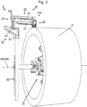
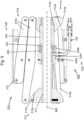
- FIG. 3 to 5 shown second embodiment of the peeling device S according to the invention also includes a clamping assembly 10 and a peeling assembly 20 with a peeling arm unit 30, a peeling knife arrangement 40 and a peeling arm carrier 60, which are identical to the corresponding assemblies of the peeling device S according to Figures 1 and 2 are constructed and designed.
- the second embodiment of the Figures 3 to 5 differs from the first exemplary embodiment accordingly Figures 1 and 2 in the structure of the force application unit 70.
- the force application unit 70 of the peeling device S In addition to a pressure plate 72, which has the same structure as the pressure plate 52 and has a corresponding pressure plate section 74, it also includes an elastic element 78, which is arranged between the pressure plate section 74 and the first end 34a of the peeling arm element 34 and through corresponding guide or securing elements 76 is secured in its position.
- the tensioning lever arrangement 80 comprises a tubular sleeve 82, the cross section of which essentially corresponds to the cross section of the peeling arm carrier 60, but is slightly larger than this, and which is displaceably arranged on the peeling arm carrier 60.
- the sleeve 82 can be detachably connected to the peeling arm carrier 60, for example by means of appropriate locking screws or another suitable clamping device, in order to secure it in its position on the peeling arm carrier 60.
- a clamping lever 84 with a first end 84a and a second end 84b is attached to the sleeve 82 so that it can pivot about an axis of rotation 86 arranged in the area of the second end 84b.
- the axis of rotation 86 extends essentially perpendicular to the longitudinal extent of the peeling arm carrier 60 and transversely to the central axis MS of the clamping assembly 10.
- the axis of rotation 86 can extend through the peeling arm carrier 60 and the sleeve 82 in order to fix the sleeve 82 on the peeling arm carrier 60.
- the tensioning lever 84 has an eccentric cam 88 in the area of its second end 84b. This is designed in such a way that the distance between the axis 86 and the long side edge of the clamping lever 84 on the long side of the clamping lever 84 is smaller than the distance between the axis of rotation 86 and the front end of the clamping lever 84.
- the pressure plate 72 is in the pre-stressed state of the peeling assembly 20, like this one in Fig. 4 is shown, compared to the unbiased state shown in Fig. 3 can be seen, towards the second end 64 of the peeling arm carrier 60 is displaced, whereby the elastic element 78 is compressed.
- the eccentric cam 88 can be designed such that the clamping lever 84 is secured against unintentional actuation in the pre-stressed state of the peeling assembly 20 in this clamping position.
- a correspondingly designed end face of the clamping lever 84 can be provided in the area of the eccentric cam 88, which can have a flattening or a locking element which interacts with the corresponding surface of the pressure plate 72.
- the tensioning lever 84 is designed accordingly Figures 3 to 5 formed by two identical partial levers which are arranged on two opposite sides of the sleeve 82.
- the partial levers it is possible for the partial levers to be connected to one another not only via the axis of rotation 86, but also at their free ends, so that, for example, the sections pointing away from the axis of rotation 86 form a common U-shaped section, which in the prestressed state the peeling assembly 20 accordingly Fig. 4 , which encompasses the peeling arm carrier 60.
- Fig. 6 shows a schematic, perspective view of a third exemplary embodiment of a peeling device according to the present invention, but without an associated clamping assembly, such as the clamping assembly 10.
- an associated clamping assembly such as the clamping assembly 10.
- this peeling device includes a peeling assembly 120 and a force application unit 150, which are arranged at the upper, second end 164 of the peeling arm carrier 160.
- the peeling arm carrier 160 essentially has a cuboid shape and includes an elongated hole 166 which extends at least approximately parallel to the longitudinal extent of the peeling arm carrier 160 and which extends from its first End 162 extends in the direction of its second end 164 and perpendicular to the longitudinal extent of the peeling arm carrier 160 through it.
- the peeling arm carrier 160 can be attached to a clamping assembly, such as the clamping assembly 10, by means of the elongated hole 166, as explained in connection with the first and second exemplary embodiments of the peeling device S.
- the peeling arm carrier 160 is, as also in Fig.
- a U-shaped recess 167 which extends at least approximately perpendicular to the longitudinal axis of the peeling arm carrier 160 over the entire width of the carrier 160, extends from the end face of the peeling arm carrier 166 in the direction of the first end 162.
- the depth of the recess 167 corresponds to approximately the height of the peeling arm unit 130, and the width of the recess 167 corresponds approximately to the width of the peeling arm unit 130.
- the peeling assembly 120 includes the peeling arm unit 130 and the peeling knife arrangement 140.
- the peeling arm unit 130 has two parallel and spaced-apart first and second peeling arm elements 134, 132, each with first and second ends 132a, 134a; 132b, 134b.
- the peeling arm elements 132, 134 which have a square cross section, lie in the common plane of the peeling arm unit 130 and the central axis MS of the clamping assembly, i.e. they are arranged one above the other in the radial direction with respect to the central axis MS of the clamping assembly.
- the first ends 132a, 134a of the peeling arm elements 132, 134 are received in the recess 176 of the peeling arm carrier 160 and are held in an articulated manner therein via hinge bolts 136a, 138a.
- the hinge pins 136a, 138a are aligned transversely to the longitudinal extent of the peeling arm carrier 160 and perpendicular to the central axis MS of the clamping assembly.
- the first end 134a of the first peeling arm element 134 projects beyond the first end 132a of the second peeling arm element 132 and protrudes from the recess 167.
- a force application unit or biasing unit 150 is arranged at the second end 164 of the peeling arm carrier 160.
- the screw head of the adjusting screw 152 at least partially covers the first end 134a of the first peeling arm element 134.
- the force application unit or biasing unit 150 further comprises an elastic element in the form of a spring 154 which is arranged in the recess 167 and acts on the first end 134a of the first peeling arm element 134 , like this one Fig. 7 you can see.
- the second ends 132b, 134b of the peeling arm elements 132, 134 are articulated via hinge bolts 136b, 138b to a support element 139, which has a substantially cuboid shape and is arranged laterally next to the second ends 132b, 134b of the peeling arm elements 132, 134.
- the lower end of the carrier element 139 projects beyond the second peeling arm element 132 in the direction of the central axis MS of the clamping assembly.
- the paring knife arrangement 140 is attached to the lower end of the carrier element 139.
- the peeling knife arrangement 140 includes a peeling knife 144, which is fastened to the lower end of the carrier element 139 with a fastening element (not shown), such as a screw.
- Fig. 6a shows an enlarged view of a first embodiment of a carrier element 139a of the peeling device Fig. 6 .
- the support element 139a has two bores 139c, the inner diameter of which corresponds to the outer diameter of the hinge pins 136b, 138b, and into which the hinge pins 136b, 138b extend.
- the hinge pins 136a, 138a, 136b, 138b thus form a parallelogram, whereby the alignment of the support element 139a, and thus the alignment of the peeling knife arrangement 140, is maintained when the peeling arm unit 130 is pivoted about the pivot axes formed by the hinge pins 136a, 138a, 136b, 138b .
- Fig. 6b shows an enlarged view of a second embodiment of a carrier element 139b of the peeling device Fig. 6 .
- the support elements 139a, 139b are constructed identically and only differ in the design of the upper hole.
- the support element 139b has an upper bore 139d, which is designed as a part-circular elongated hole, with a circular arc that runs concentrically to the bore 139c, as shown in FIG Fig. 6b circle shown by broken lines.
- the radius of the circular arc corresponds to the distance between the centers of the holes 139c, 139d.
- This design of the bore 139d allows additional pivoting of the carrier element 139b, and thus of the paring knife 144, around the bolt 136b.
- This additional pivotability of the peeling knife 144 enables a further adaptation of the peeling device to the tubular body R to be processed, for example in the event that the end of the tubular body R is conical.
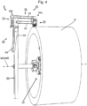
- Fig. 7 is a perspective view of a fourth embodiment of a peeling device according to the invention.
- This includes a clamping assembly 10, to which, via the spindle 16, the peeling arm carrier 160 is attached with its lower, first end 162.
- a peeling assembly 220 with a peeling arm unit 230 is arranged, which essentially corresponds to the structure of the peeling arm unit 130.
- the peeling arm unit 230 differs from the peeling arm unit 130 in the design of the support element 239, which has a substantially L-shaped shape and in which the bores receiving the hinge pins 136b, 138b are arranged at the ends of the L.
- the second end 232b of the peeling arm element 232 is shorter than the second end 234b of the peeling arm element 234, so that one leg of the carrier element 239 has a substantially vertical orientation, while the other leg is aligned approximately horizontally to the peeling arm element 232.
- the distance between the hinge pins 138a, 138b is greater than the distance between the hinge pins 136a, 136b. This changes the orientation of the carrier element 239, and thus also the orientation of the Peeling knife 144 to the tubular body R to be processed while the peeling arm unit 230 is pivoted.
- the hole 239d at the end of the horizontally aligned leg is designed as a part-circular elongated hole, with a circular arc that is concentric to the in Fig. 7a other hole that cannot be seen runs in the support element 239, and the radius of which corresponds to the distance between the centers of these holes, as shown in FIG Fig. 7a circle shown by broken lines.
- the alignment of the paring knife 144 to the tubular body R to be processed can be corrected or adjusted in such a way that the processing of a tubular body R with a conical end is possible.
- a paring knife arrangement 140 with a paring knife 144 is also arranged on the carrier element 239.
- the paring knife 144 is with a fastening element, not shown in detail, on the in Fig. 7a downward-facing side of the carrier element 239 attached.
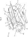
- Fig. 8 shows the clamping assembly 10 according to Figures 1 , 3 and 4 .
- the clamping assembly 10 includes the carrier sleeves 12 with the in Fig. 6 nut 18 attached to the left end and firmly connected to the carrier sleeve 12.
- the first flange 13 is axially fixed, but rotatable about the central axis of the carrier sleeve 12, which is aligned coaxially with the central axis MS of the clamping assembly 10.
- the second flange 13 is arranged to be axially movable on the right end of the carrier sleeve 12.
- the carrier sleeve 12 has the external thread 12a in the area of its right end, which interacts with the corresponding internal thread of the second flange 13.
- the flanges 13 are essentially conical with a cone base 13a and a tapered cone end 13b, the central axis of the flange 13 being aligned coaxially with the central axis of the carrier sleeve 12.
- the tapering ones Cone ends 13b point towards each other.
- the clamping scissor elements 14a, 14b of the clamping scissors 14, which are each articulated in pairs, are arranged in an articulated manner in such a way that they can be pivoted about an axis perpendicular to the central axis MS of the clamping assembly 10.
- approximately U-shaped support elements 15 are arranged, which are aligned in their longitudinal extent at least approximately parallel to the central axis MS of the clamping assembly 10, and have their open side facing the central axis MS of the clamping assembly 10 . Due to their articulated connection to one clamping scissor element 14a, 14b and the connection through an elongated hole to the corresponding other clamping scissor element 14b, 14a, the support elements 15 remain in this orientation. When the peeling device S is ready for use, i.e. when it is assembled, the support elements 15 rest on the inside of the tubular body R.
- a holding element H in the form of a tether is also attached on the clamping assembly 10 the Fig. 6 .
- the holding element or holding band H is fastened with its ends to the cone base 13a of the flanges 13 approximately centrally between two adjacent clamping scissors 14.
- the length of the retaining strap H is chosen so that it is in Fig. 6 shown, relaxed state of the clamping assembly 10, in which the flanges 13 reach their maximum distance from one another, is tensioned between the flanges 13.
- the retaining strap H can also serve as a limit for the maximum possible folding of the clamping assembly 10.
- a fixed handle can also be used as the holding element H, which is attached, for example, with one end to one of the flanges 13 and with its second end extending in the direction of the second flange 13.
- a firm grip could, similar to the support element 15, have a Elongated hole in the area of its other end can be connected to the second flange 13, whereby the mobility of the two flanges 13 is maintained, but the handling of the clamping assembly 10 can be improved.
- Fig. 9 is a sectional view of a second exemplary embodiment of a clamping assembly 310 according to the invention with a central axis MS.
- the clamping assembly 310 comprises a carrier shaft or carrier sleeve 312 designed as a hollow shaft with an in Fig. 9 First flange 313 attached to the left end and firmly connected to the carrier sleeve 312. On the in Fig. 9 At the right end of the carrier sleeve 312, a second flange 313 is arranged axially displaceably on the carrier sleeve 312. The carrier sleeve 312 is arranged coaxially to the central axis MS of the clamping assembly 310.
- the essentially conical flanges 313 have a conical base 313a and a tapered conical end 313b directed towards the center of the carrier sleeve 312.
- pairs of clamping scissor elements 314a, 314b of clamping scissors 314 are arranged in an articulated manner in such a way that they can each be pivoted about an axis perpendicular to the central axis MS of the clamping assembly 310.
- the clamping scissors 314 correspond in their structure and functionality to the clamping scissors 14 of the clamping assembly 10.
- approximately U-shaped support elements 315 are arranged, which are aligned in their longitudinal extent at least approximately parallel to the central axis MS of the clamping assembly 310, and have their open side facing the central axis MS of the clamping assembly 310. They are connected in an articulated manner to one clamping scissor element 314a, 314b and through an elongated hole to the corresponding other clamping scissor element 314b, 314a and therefore remain in this orientation during the actuation of the clamping scissors 314.
- the support elements 315 rest on the inside of the tubular body R.
- the clamping assembly 310 has an actuating mechanism 320.
- the actuating mechanism 320 comprises a piston-cylinder mechanism with an annular piston 322 which is axially fixed on the hollow shaft or carrier sleeve 312 and a sleeve-shaped cylinder 324 which is arranged coaxially to the central axis MS of the clamping assembly 310 on the carrier sleeve 312.
- the cylinder 324 rests with its inner surface on the outer circumferential surface of the piston 322 in a fluid-tight manner and is held displaceably in the axial direction.
- the actuating mechanism 320 further comprises a sleeve-shaped connection element 326 arranged coaxially to the central axis MS of the clamping assembly 310 on the carrier sleeve 312, with a connection section 326a and a fastening section 326b.
- connection section 326a corresponds to the outer diameter of the carrier sleeve 312 and is held slidably thereon.
- the connection section 326a also has a connection bore 326c, to which a fluid source, such as a hydraulic pump, can be connected via a fluid line HS, such as a hydraulic hose.
- the right flange 313 has on its side facing the actuating mechanism 320 a cylindrical recess 313c, which is aligned coaxially with the carrier sleeve 312, the diameter of which corresponds to the outer diameter of the cylinder 324, and into which the right end of the cylinder 324 projects and is fastened there is.
- An annular cylinder space 328 is formed on the outside of the carrier sleeve 312.
- the cylinder space 328 is in fluid communication with the connection bore 326c, so that a fluid conveyed via the fluid line HS reaches the cylinder space 328.
- the flange 313, the cylinder 324 and the connecting element 326 are connected to one another firmly and in a fluid-tight manner. If a fluid is conveyed under pressure into the cylinder space 328 via the fluid line HS, the connecting element 326 with the cylinder 324 and the right flange 313 attached to it shifts accordingly Fig. 9 to the left, whereby the cylinder space 328 is enlarged.
- This movement of the flange 313 activates the clamping scissors 314, which extend radially outwards and clamp the clamping assembly 310 in the tubular body R.
- the fluid under pressure in the cylinder 324 can be relieved by actuating a corresponding backflow valve.
- a backflow valve can be assigned to the fluid source, for example arranged on it.
- it is possible that such a backflow valve is arranged on the actuating mechanism 320 of the clamping assembly 310 or is part of the fluid line HS.
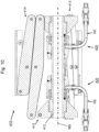
- Fig. 10 a sectional view of a third exemplary embodiment of a clamping assembly 410 according to the invention.
- the clamping assembly 410 like the clamping assembly 310, includes accordingly Fig. 9 , a hollow shaft or carrier sleeve 412, on the in Fig. 10 right end a first flange 413 is displaceably arranged.
- a first actuating mechanism 420 is also arranged on the carrier sleeve 412 and is in its Structure corresponding to that of the clamping assembly 310 Fig. 9 known actuating mechanism 320 corresponds.
- the clamping assembly 410 also includes a further actuation mechanism 420, which is also arranged on the carrier sleeve 412.
- This further actuation mechanism 420 is constructed identically to the first actuation mechanism 420, but arranged in mirror image thereto, and with the in Fig. 10 left flange 413 connected.
- Clamping scissors 414 are arranged on the flanges 413 and are constructed identically to the clamping scissors 314 of the clamping assembly 310.
- both actuation mechanisms 4320 are each connected to a fluid source via a fluid line HS. It is possible that both fluid lines HS are connected to the same source and can either be controlled together or separately. The actuation can take place simultaneously or one after the other.
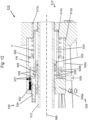
- Fig. 11 shows a sectional view of a fourth exemplary embodiment of a clamping assembly 510 according to the invention.
- the structure of the first flange 513 essentially corresponds to the first flange 312 according to the second exemplary embodiment of the clamping assembly 310 Fig. 9 .
- the clamping assembly 510 also points to the in Fig. 11 left end of the carrier sleeve 512 has a fixed second flange 513.
- Clamping scissors 514 are arranged on the flanges 512, the structure and functioning of which correspond to the clamping scissors 314 of the clamping assembly 310.
- the clamping assembly 510 has an actuation mechanism 520.
- the actuating mechanism 520 comprises a piston-cylinder mechanism with an annular piston 522 which is axially fixed on the carrier sleeve 512 and a sleeve-shaped cylinder 524 which is coaxial with the Central axis MS of the clamping assembly 510 is arranged on the carrier sleeve 512 in a fluid-tight manner.
- the cylinder 524 rests with its inner surface on the outer surface of the piston 522 and is held displaceably in the axial direction.
- the actuating mechanism 520 further comprises a sleeve-shaped connection element 526 arranged coaxially to the central axis MS of the clamping assembly 510 on the carrier sleeve 512, with a connection section 526a, a fastening section 526b and a cylinder sleeve in the form of a tubular section 526c.
- the inner diameter of the in Fig. 11 The right end of the support sleeve 512 facing fastening section 526b of the connecting element 526 corresponds to the outer diameter of the cylinder 524, the left end of which is received in the fastening section 526b and fastened thereto in a fluid-tight manner.
- the inner diameter of the connection section 526a corresponds to the outer diameter of the carrier sleeve 512 and is held slidably thereon.
- the tubular section 526c adjoins the in Fig. 11 right end of the fastening section 526b and extends towards the right flange 513.
- the inner diameter of the cylinder sleeve or the tubular section 526c is larger than the outer diameter of the cylinder 524.
- the right flange 513 has on its side facing the actuating mechanism 520 a first cylindrical recess 513c, the diameter of which corresponds to the outer diameter of the cylinder 524, and into which the right end of the cylinder 524 projects and is fastened there.
- An annular cylinder space 528 is formed between the piston 522 and the end face of the connecting section 526a of the connecting element 526 facing the piston 522 on the one hand and the inside of the left end of the cylinder 524 and the outside of the carrier sleeve 512 opposite this surface.
- the flange 513 has a second cylindrical recess 513d on its side facing the actuating mechanism 520, which is aligned coaxially with the first recess 513c, the diameter of which corresponds to the outer diameter of the tubular section 526c of the connecting element 526, which projects into it and is fastened there.
- the actuation mechanism 520 further includes an integrated drive for actuating the clamping assembly 520, as described below in connection with Fig. 12 is explained, which is an enlarged view of the actuating mechanism 520 of the clamping assembly 510 accordingly Fig. 11 is.
- the drive of the actuation mechanism 520 includes a fluid pump 530 with a piston 532 that can be moved in a cylinder 534.
- the cylinder 534 is arranged in the connection section 526a of the connection element 526, and extends parallel to the central axis MS of the clamping assembly 520 from in Fig. 12 left end of the connection element 526 to the right into the connection section 526a.
- An annular cavity is formed between the outer surface of the cylinder 524 of the piston-cylinder assembly and the inner surface of the tubular portion 526c.
- An annular piston 540 is arranged in the cavity, which sits slidably on the outer surface of the cylinder 524 and rests with its outer peripheral surface on the inner surface of the tubular section 526c of the connecting element 526.
- the annular piston 540 divides the annular cavity.
- a fluid reservoir FR is formed on the side of the annular piston 540 facing the fluid pump 530.
- the fluid reservoir or reservoir FR is connected to the cylinder 532 of the fluid pump 530 and the annular cylinder space 528 via channels 536 arranged in the connecting element 526.
- Check valves 537 in the form of spring-loaded ball check valves are arranged in the channels 536, which prevent fluid from flowing back through the channels 536 into the reservoir FR.
- connection element 536 there are further channels 538 which connect the annular cylinder space 528 with the reservoir FR.
- a return flow valve 539 is arranged in the channels 538, which allows fluid to flow back from the annular cylinder space 528 into the reservoir FR.
- a spring element F in the form of a helical compression spring is arranged on the right side of the annular piston 540.
- the spring element or spring F is arranged coaxially on the cylinder 524 and generates a force acting on the annular piston 540 in the axial direction.
- the annular cavity to the right of the annular piston 540 is connected to the atmosphere via a corresponding ventilation hole 513e in the flange 513.
- a lever H is provided.
- the lever H is on the in Fig. 13 left-facing end face of the connecting element 526 is articulated, and connected at its lower end to the piston 534 of the fluid pump 530, so that the piston 534 can be reversibly moved back and forth by actuating the lever H in the cylinder 532.
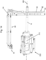
- Fig. 14 is a schematic, perspective view of a peeling device with a peeling assembly Fig. 3 and a clamping assembly Fig. 9 .
- a spindle such as the threaded spindle 16 extends through the hollow shaft or carrier sleeve 312 of the clamping assembly 310 and protrudes from the in Fig. 14 right end of the clamping assembly 310.
- the right end of the spindle 16 extends through the elongated hole 66 of the peeling arm carrier 60 which is attached thereto.
- the peeling assembly 20 with the peeling knife arrangement 40 is arranged, which extends at least approximately parallel to the central axis MS of the clamping assembly 310. How further in Fig.
- the peeling arm carrier 60 can also be provided with markings which are arranged along the elongated hole 66, and the indicate the attachment position of the peeling arm carrier 60 on the clamping assembly 310 with respect to the diameter of a tubular body R to be processed.
- the clamping assembly 10 is first positioned inside the tubular body R and clamped in such a way that the central axis MS of the clamping assembly 10 is at least approximately coaxial with the Central axis MR of the tubular body R is aligned.
- the threaded spindle 16 with the peeling arm carrier 60 and the peeling arm unit 30 located thereon is then inserted into the carrier sleeve 12, so that the peeling knife arrangement 40 is positioned radially over the section of the tubular body R to be peeled.
- a lock can be provided on the carrier sleeve 12 or the nut 18, which prevents unwanted axial displacement of the threaded spindle.
- the connection between the peeling arm carrier 60 and the left end 16a of the threaded spindle 16 is released.
- the peeling arm carrier 60 can now be moved along the end 16a of the threaded spindle 16 over the elongated hole 66 until the peeling assembly 20 or the knife carriage 42 of the peeling knife arrangement 40 with the rollers 46 stands on the tubular body R, and the peeling arm elements 32, 34 the peeling arm unit 30 are aligned at least approximately parallel to the central axis MR of the tubular body R.
- the peeling arm carrier 60 is then fixed in this position on the threaded spindle 16.
- the spring element 54 is biased by moving the pressure plate 52, for example manually, towards the second end 64 of the peeling arm carrier 60.
- the peeling arm unit 30 is not yet in the in Fig. 1 shown peeling position, ie, the spring element 54 is in an unloaded state.
- the peeling arm unit is then placed on the tubular body R and the spring element 54 is further prestressed. Due to the force exerted by the elastic element 54 on the pressure plate 52, the pressure plate 52 tilts on the peeling arm carrier 60 and is thus secured against slipping.
- a clamp (not shown) can be provided which secures the pressure plate 52 in its position on the peeling arm carrier 60, for example against unintentional displacement when load changes may occur.
- the clamping lever 84 which is located before the peeling assembly 20 is brought to the surface of the tubular body R in the in Fig. 3 in the open position shown in Fig. 4 shown clamping position, whereby the pressure plate 72 is moved towards the second end 64 of the peeling arm carrier 60.
- the force generated by the force application unit or biasing device 50, 70, with which the knife carriage 42 is pressed onto the surface of the tubular body R should be greater than the force with which the paring knife 44 is pressed against the knife carriage 42 by the spring element located in the knife carriage 42 Pipe surface is pressed to prevent the knife carriage 42 from being lifted off the tubular body R. This ensures that any existing ovalities in the tubular body R are reliably compensated for and ensures that the paring knife 44 rests on the tubular body R with a constant force.
- the peeling arm carrier 160 can be attached to the spindle 16 in the same way.
- the spindle 16 can thus be easily attached to the marking corresponding to the diameter of the tubular body R to be machined.
- the adjusting screw 152 of the force application unit or biasing unit 150 is actuated.
- the spring 154 acting on the first end 134a of the peeling arm element 134 is relieved.
- the peeling knife assembly 140 can move further towards the surface of the tubular body R, but a radial springback requires less force than with a more strongly preloaded spring F. If, on the other hand, the spring F is further tensioned by screwing the adjusting screw into the peeling arm carrier 160, a greater force is necessary for further compression.
- the peeling device S with the peeling assembly 20 is driven to rotate around the tubular body R. This can be done manually if, for example, a handle is provided in the area of the second end 64 of the peeling arm carrier 60.
- a handle is provided in the area of the second end 64 of the peeling arm carrier 60.
- an electrical device such as a cordless screwdriver or a drill, which can be attached to the attachment point of the threaded spindle 16 on the peeling arm carrier 60 using a corresponding adapter.
- the position of the peeling assembly 20 can be adjusted or changed along the central axis MS of the clamping element 10 or the central axis R of the tubular body R. This can be done gradually or continuously.
- care must be taken to ensure that the feed length corresponds at most to the width of the paring knife 44 in order to achieve uniform material removal in the axial direction. If the axial feed is continuous, it should this also corresponds to a maximum of the width of the peeling knife 44 during one revolution of the peeling assembly 20 around the tubular body R.
- a gradual axial advance can be achieved by releasing the connection between the peeling arm support 60 and the threaded spindle 16 after each revolution of the peeling assembly 20 about the tubular body R, and the peeling arm support 60 on the threaded spindle 16 by a corresponding amount along the central axis MR of the tubular body R is moved and fixed again.
- the threaded spindle 16 screws into or through the clamping assembly 10 by a desired length with each revolution of the peeling assembly 20 around the tubular body R.
- the clamping assembly 10 can, for example, have a corresponding threaded sleeve which receives the threaded spindle 16.
- the peeling arm carrier 60 is attached to the end 16a of the spindle 16 in a radially fixed manner but rotatable about the central axis MS of the clamping assembly 10.
- the threaded spindle 16 is manually screwed into or through the clamping assembly 10 by a desired length after each revolution of the peeling assembly 20 around the tubular body R.
- the peeling device S according to the invention can also be equipped with a clamping assembly 310, 410, 510, the operation of which is explained below.
- the clamping assembly 310 according to the in connection with Fig. 9
- the second exemplary embodiment explained is inserted coaxially into the tubular body R to be processed.
- a pressurized fluid such as hydraulic oil
- the pressurized fluid moves the connecting element 326 axially away from the piston 322, which is fixedly arranged on the carrier sleeve 312.
- the flange 313, which is also firmly connected to the cylinder 324 is also displaced on the carrier sleeve 312.
- the support elements 315 move radially away from the central axis MS of the clamping assembly 310 until they rest on the inside of the tubular body R and clamp the clamping assembly 310 therein.
- the clamping assembly 410 accordingly Fig. 10 includes two actuation mechanisms 420. These function in the same manner as the actuation mechanism 320 of the clamping assembly 310.
- the actuation mechanisms 420 of the clamping assembly 410 can be actuated individually, whereby only one of the flange 413 at a time, as in connection with Fig. 9 described, is moved on the carrier sleeve 312. It may be sufficient to activate only one of the actuation mechanisms 420. However, both actuation mechanisms 420 can also be activated one after the other. In addition, it is also possible to activate both actuation mechanisms 420 simultaneously in order to clamp the clamping assembly 410 in the tubular body R to be machined.
- the pressurized fluid is relieved by allowing backflow into the fluid source.
- the clamping scissors 314, 414 relieved in this way can be pushed together manually.
- the clamping assembly 510 is held coaxially in the tubular body R to be machined.
- the lever H is moved back and forth, whereby the fluid pump 530 is actuated.
- fluid such as hydraulic oil
- the check valves 537 arranged in the channels 536 prevent backflow of pressurized fluid into the reservoir FR during the clamping of the clamping assembly 510.
- the pressurized fluid causes the connecting element 526 to move axially away from that on the carrier sleeve 512 fixed piston 522 moved away.
- the flange 513 is also displaced on the carrier sleeve 512.
- the clamping scissors 514 are activated and the clamping assembly 510 is clamped in the tubular body R.
- the return flow valve 539 is activated, whereby the pressurized fluid located in the annular cylinder space 528 can flow back into the fluid reservoir FR via the channels 538.
- the clamping scissors 514 can be manually compressed.
- the size of the fluid reservoir FR changes in accordance with the amount of fluid removed or returned, with the annular piston 540 being moved accordingly.
- the spring F acting on the side of the annular piston 540 facing away from the fluid reservoir FR prevents the annular piston 540 from tilting and air from penetrating into the hydraulic system.
- Clamping assemblies 310, 410, 510 described are fluid-operated. It is therefore understood that between the relatively movable elements of the assemblies that come into contact with the fluid, corresponding seals are provided, which prevent an unwanted leakage of fluid or an equally unwanted penetration of outside air into the fluid system.
- the peeling arm carrier 60, 160 is in the exemplary embodiments Figures 1 to 7 shown with a substantially square cross section. Of course, it is possible for the peeling arm carrier 60, 160 to have a different cross section, for example a square, triangular or round cross section.
- additional positive locking means can be provided in order to To further stabilize the peeling arm carrier 60, 160, and above all to avoid unwanted twisting of the peeling arm carrier 60, 160 about an axis in its longitudinal extent, such as sleeves or clamps that prevent the peeling arm carrier 60, 160 from tilting relative to the threaded spindle 16.
- a further pressure plate is provided at the second end 64 of the peeling arm carrier 60, which is arranged between the first end 34a of the peeling arm element 34 and the elastic element 54.
- the securing and positioning element 56, 76 is arranged on this further pressure plate.
- a spindle acting on this pressure plate, or a similarly acting element can be attached to the first end 34a of the peeling arm element 34, which can be moved, for example, by means of a corresponding knob in order to move the pressure plate in the direction of the elastic element 54 in order to achieve a further adjustment of the preload must be made.
- all elements of the peeling device according to the invention can be made of a suitable metal, such as steel or aluminum, in order to ensure the required strength.
- a suitable metal such as steel or aluminum
- the second flange 13 has an internal thread which cooperates with a corresponding external thread on the right end of the carrier sleeve 12 in order to move the flange 13 on the carrier sleeve 12 in the axial direction for tensioning and relaxing the clamping scissors 14.
- the axial mobility of the second flange 13 can be achieved using other means.
- the right side of the carrier sleeve 12 can be designed as a hydraulic or pneumatic piston, on which the second flange 13, designed as a hydraulic or pneumatic cylinder, can be reversibly moved by means of a corresponding hydraulic or pneumatic pump.
- a peeling device S comprises a clamping assembly, a peeling arm carrier and a peeling assembly with a peeling arm unit. It is possible to combine each clamping assembly 10, 310, 410, 510 with each of the peeling arm supports 60,160 and each of the peeling arm units 30,130, 230.
- clamping assemblies 10, 310, 410, 510 in addition to a peeling tool, generally as a tool holder for any type of tool for processing an approximately tubular body, such as a pipe cutter or a thread cutter.
- a peeling tool generally as a tool holder for any type of tool for processing an approximately tubular body, such as a pipe cutter or a thread cutter.
- it can be arranged directly on the clamping assembly 10, 310, 410, 510 or on the peeling arm carrier 60,160.
- Peeling device for at least partially removing the surface of an at least approximately tubular body with a central axis, in particular a plastic pipe, comprising: a clamping assembly with a central axis and at least one clamping element for clamping the peeling device on the tubular body, the central axis of the in the assembled state Clamping assembly coincides at least approximately with the central axis of the tubular body, and a peeling assembly with a peeling arm unit, a peeling knife arrangement arranged at a first end of the peeling arm unit and a peeling arm carrier with a first end and a second end which connects the clamping assembly to the peeling arm unit, wherein the Peeling arm unit with a second end is connected to the peeling arm carrier in such a way that the peeling arm unit and the central axis of the clamping assembly lie in a common plane in the assembled state, the peeling knife arrangement having a peeling knife, the peeling arm unit having its first and second ends in this way with the peeling knife arrangement and connected to
- Example 2 Peeling device according to Example 1, further comprising a force application unit for reversibly biasing the peeling arm unit in a peeling position in a direction in the common plane of the peeling arm unit and the central axis of the clamping assembly.
- Example 3 Peeling device according to one of Examples 1 or 2, wherein the clamping assembly has more than one clamping element, preferably three clamping elements, preferably in the form of clamping scissors.
Landscapes
- Engineering & Computer Science (AREA)
- Mechanical Engineering (AREA)
- Life Sciences & Earth Sciences (AREA)
- Forests & Forestry (AREA)
- Turning (AREA)
- Automatic Assembly (AREA)
Applications Claiming Priority (2)
| Application Number | Priority Date | Filing Date | Title |
|---|---|---|---|
| DE102020120792.1A DE102020120792A1 (de) | 2020-08-06 | 2020-08-06 | Gelenkig gelagerter Messerhalter |
| EP21190093.1A EP3950187B1 (fr) | 2020-08-06 | 2021-08-06 | Dispositif de raclage et assemblage de serrage |
Related Parent Applications (2)
| Application Number | Title | Priority Date | Filing Date |
|---|---|---|---|
| EP21190093.1A Division-Into EP3950187B1 (fr) | 2020-08-06 | 2021-08-06 | Dispositif de raclage et assemblage de serrage |
| EP21190093.1A Division EP3950187B1 (fr) | 2020-08-06 | 2021-08-06 | Dispositif de raclage et assemblage de serrage |
Publications (2)
| Publication Number | Publication Date |
|---|---|
| EP4286080A2 true EP4286080A2 (fr) | 2023-12-06 |
| EP4286080A3 EP4286080A3 (fr) | 2024-03-06 |
Family
ID=77249735
Family Applications (2)
| Application Number | Title | Priority Date | Filing Date |
|---|---|---|---|
| EP23198307.3A Pending EP4286080A3 (fr) | 2020-08-06 | 2021-08-06 | Ensemble de serrage servant de porte-outil pour un outil |
| EP21190093.1A Active EP3950187B1 (fr) | 2020-08-06 | 2021-08-06 | Dispositif de raclage et assemblage de serrage |
Family Applications After (1)
| Application Number | Title | Priority Date | Filing Date |
|---|---|---|---|
| EP21190093.1A Active EP3950187B1 (fr) | 2020-08-06 | 2021-08-06 | Dispositif de raclage et assemblage de serrage |
Country Status (3)
| Country | Link |
|---|---|
| US (1) | US11986970B2 (fr) |
| EP (2) | EP4286080A3 (fr) |
| DE (1) | DE102020120792A1 (fr) |
Families Citing this family (8)
| Publication number | Priority date | Publication date | Assignee | Title |
|---|---|---|---|---|
| CN114603195B (zh) * | 2022-03-10 | 2023-03-31 | 江苏华东电力冶金机械总厂有限公司 | 一种波纹管双头同步切割设备 |
| CN115041730A (zh) * | 2022-07-11 | 2022-09-13 | 中核华辰建筑工程有限公司 | 一种新型钻孔便携式手持辅助工具 |
| AU2023319140A1 (en) * | 2022-08-03 | 2025-03-20 | Panther PE Tools Pty Ltd | Facing tool assembly |
| CN115365566B (zh) * | 2022-09-22 | 2023-12-15 | 济南市平阴鑫森有限责任公司 | 一种胶辊铁芯自动切割装置 |
| CN115488933B (zh) * | 2022-09-27 | 2023-05-12 | 浙江科达利实业有限公司 | 一种新能源汽车二氧化碳管测量切割装置 |
| EP4427913A1 (fr) * | 2023-03-07 | 2024-09-11 | Georg Fischer Rohrleitungssysteme AG | Support de raccord |
| CN118219009A (zh) * | 2024-04-30 | 2024-06-21 | 上海第一机床厂有限公司 | 伸缩式内支承及其使用方法 |
| CN119099000B (zh) * | 2024-11-08 | 2025-01-10 | 江西虔塑管业有限公司 | 一种pe给水管生产用的批量加工装置 |
Citations (2)
| Publication number | Priority date | Publication date | Assignee | Title |
|---|---|---|---|---|
| EP0217704A1 (fr) | 1985-09-19 | 1987-04-08 | Gaz De France | Appareil pour gratter la surface extérieure d'un tube |
| EP1160035A1 (fr) | 2000-06-02 | 2001-12-05 | Paul T. Golletz | Appareil d' écroutage compacte pour écrouter un tube ou câble |
Family Cites Families (20)
| Publication number | Priority date | Publication date | Assignee | Title |
|---|---|---|---|---|
| US2501893A (en) * | 1948-07-14 | 1950-03-28 | Joseph F Francis | Pipe beveling machine |
| DE1214512B (de) * | 1963-06-19 | 1966-04-14 | Hermann Rosorius Ingenieurbuer | Spreizdorn zum Zentrieren von rohrartigen Werkstuecken unterschiedlicher Durchmesser |
| US4393761A (en) * | 1981-07-06 | 1983-07-19 | Murphy Robert P | Floating knife assembly for a meat defatting machine |
| JPS5859502U (ja) * | 1981-10-16 | 1983-04-22 | 日本鋼管株式会社 | 管端切削装置 |
| US5076025A (en) * | 1990-12-05 | 1991-12-31 | Mathey International, Ltd. | Land grinder mount |
| US5458031A (en) * | 1993-11-23 | 1995-10-17 | Coiltech Corporation | Core cutter |
| US5771586A (en) * | 1994-09-07 | 1998-06-30 | Flexible Steel Lacing Company | Apparatus for skiving belt ends |
| DE29516513U1 (de) | 1995-09-19 | 1997-01-30 | Golletz, Paul T., 61348 Bad Homburg | Schneid-Schälwerkzeuge zum manuellen Aufschneiden und/oder Einschneiden und/oder Schälen eines Rohres, insbesondere Kunststoffrohr |
| IT1294817B1 (it) * | 1997-07-11 | 1999-04-15 | Perini Fabio Spa | Macchina ribobinatrice - taglierina per la produzione di rotoli di materiale nastriforme e relativo metodo |
| EP1075910A1 (fr) * | 1999-08-10 | 2001-02-14 | Fort James France | Machine de découpe d'un rouleau de papier |
| DE20117063U1 (de) | 2000-10-22 | 2002-01-17 | Golletz, Paul T., 61348 Bad Homburg | Schneidvorrichtung und Schälwerkzeug zum Abschälen einer äußeren Schicht oder Schichten eines Rohres oder Kabels |
| RU2200075C2 (ru) * | 2001-02-12 | 2003-03-10 | Общество с ограниченной ответственностью Фирма "Техносервис" | Мобильное токарное устройство для обработки торцов крупногабаритных обечаек |
| US20030084772A1 (en) * | 2001-11-05 | 2003-05-08 | Shen Ying Liang | Cutting device of packaging machine |
| ITPD20030241A1 (it) | 2003-10-10 | 2005-04-11 | Ritmo Spa | Attrezzatura per la preparazione della zona di saldatura |
| DE102005055114A1 (de) | 2005-11-18 | 2007-05-24 | Dipl.-Ing. H. Schulz Hds Hydraulik Gmbh & Co. Kg | Schälwerkzeug für Schläuche und Verfahren zum Schälen von armierten Schläuchen |
| DE102009010776B4 (de) * | 2009-02-26 | 2016-07-14 | Gbz Mannheim Gmbh & Co. Kg | Schälgerät zur Bearbeitung von Kunststoffrohren oder von mit Kunststoff beschichteten Rohren |
| DE202009010958U1 (de) | 2009-08-16 | 2011-01-05 | Gbz Mannheim Gmbh & Co. Kg | Schälvorrichtung für Kunststoffrohre mit großem Durchmesser |
| DE202010013750U1 (de) | 2010-10-01 | 2012-01-13 | Friatec Ag | Messer für ein Schälgerät |
| CA2984297A1 (fr) * | 2017-02-28 | 2018-08-28 | Gregg R. Bruinsma | Dispositif et methode de dressage d'extremite de tuyau |
| US11504871B2 (en) * | 2019-10-16 | 2022-11-22 | Robert A. Blasi | Shaft cutting tool |
-
2020
- 2020-08-06 DE DE102020120792.1A patent/DE102020120792A1/de not_active Withdrawn
-
2021
- 2021-08-04 US US17/394,306 patent/US11986970B2/en active Active
- 2021-08-06 EP EP23198307.3A patent/EP4286080A3/fr active Pending
- 2021-08-06 EP EP21190093.1A patent/EP3950187B1/fr active Active
Patent Citations (2)
| Publication number | Priority date | Publication date | Assignee | Title |
|---|---|---|---|---|
| EP0217704A1 (fr) | 1985-09-19 | 1987-04-08 | Gaz De France | Appareil pour gratter la surface extérieure d'un tube |
| EP1160035A1 (fr) | 2000-06-02 | 2001-12-05 | Paul T. Golletz | Appareil d' écroutage compacte pour écrouter un tube ou câble |
Also Published As
| Publication number | Publication date |
|---|---|
| US11986970B2 (en) | 2024-05-21 |
| EP3950187B1 (fr) | 2024-06-26 |
| EP4286080A3 (fr) | 2024-03-06 |
| EP3950187A2 (fr) | 2022-02-09 |
| US20220040874A1 (en) | 2022-02-10 |
| DE102020120792A1 (de) | 2022-02-10 |
| EP3950187A3 (fr) | 2023-03-08 |
Similar Documents
| Publication | Publication Date | Title |
|---|---|---|
| EP3950187B1 (fr) | Dispositif de raclage et assemblage de serrage | |
| DE102015115433B4 (de) | Greif- und Hebevorrichtung zum Greifen von einem Greifgut mit zumindest zwei Greifzangen | |
| EP0910497A1 (fr) | Serre-joints | |
| EP0928602A2 (fr) | Outil pour cisaillement d'implants | |
| DE20219954U1 (de) | Auspreßvorrichtung für exzentrische Traggelenke | |
| DE102015112724A1 (de) | Stanzbacken und Stanzgerät mit einer Stanzhülse und einer Stanzöffnung | |
| EP3269509A1 (fr) | Pince pour réaliser des trous sur des profiles à section trapézodale | |
| WO2019158590A1 (fr) | Dispositif tendeur | |
| DE202008009394U1 (de) | Vorrichtung zum lösbaren Verschließen des Endes eines Rohres | |
| AT16129U1 (de) | Vorrichtung und Verfahren zur Montage von Buchsen auf Wellen | |
| DE2851746C2 (de) | Bandvorschubgerät | |
| EP1353779A2 (fr) | Dispositif permettant de visser des elements de fixation | |
| DE29805584U1 (de) | Montagevorrichtung zum Auswechseln von Silentlagern | |
| DE10234603B4 (de) | Spanneinrichtung für Werkzeuge oder Werkstücke | |
| DE19521438A1 (de) | Bohrhilfsvorrichtung für eine Bohrmaschine, eine Bohrmaschine sowie Verfahren zum Bohren von Werkstücken | |
| EP1840049B1 (fr) | Elément de prise pour une bouteille de gaz | |
| EP1810784B1 (fr) | Dispositif de serrage de tubes à réglage variable | |
| DE102023131331B3 (de) | Mitnahmewerkzeug mit verstellbarer Mitnahmekontur | |
| EP2881192A1 (fr) | Mâchoires pivotantes et appareil manuel motorisé | |
| DE19501312B4 (de) | Halter für Trommeln, zur Verwendung an Trommelständern | |
| EP1698435B1 (fr) | Outil dynamométrique à application manuelle du couple avec poignée extensible | |
| EP4640374A1 (fr) | Dispositif de serrage | |
| DE3611284C2 (fr) | ||
| DE29616065U1 (de) | Pinzette | |
| DE20210128U1 (de) | Distraktionsgerät |
Legal Events
| Date | Code | Title | Description |
|---|---|---|---|
| PUAI | Public reference made under article 153(3) epc to a published international application that has entered the european phase |
Free format text: ORIGINAL CODE: 0009012 |
|
| STAA | Information on the status of an ep patent application or granted ep patent |
Free format text: STATUS: THE APPLICATION HAS BEEN PUBLISHED |
|
| AC | Divisional application: reference to earlier application |
Ref document number: 3950187 Country of ref document: EP Kind code of ref document: P |
|
| AK | Designated contracting states |
Kind code of ref document: A2 Designated state(s): AL AT BE BG CH CY CZ DE DK EE ES FI FR GB GR HR HU IE IS IT LI LT LU LV MC MK MT NL NO PL PT RO RS SE SI SK SM TR |
|
| PUAL | Search report despatched |
Free format text: ORIGINAL CODE: 0009013 |
|
| AK | Designated contracting states |
Kind code of ref document: A3 Designated state(s): AL AT BE BG CH CY CZ DE DK EE ES FI FR GB GR HR HU IE IS IT LI LT LU LV MC MK MT NL NO PL PT RO RS SE SI SK SM TR |
|
| RIC1 | Information provided on ipc code assigned before grant |
Ipc: B26D 3/16 20060101ALI20240130BHEP Ipc: B23B 5/16 20060101AFI20240130BHEP |
|
| STAA | Information on the status of an ep patent application or granted ep patent |
Free format text: STATUS: REQUEST FOR EXAMINATION WAS MADE |
|
| 17P | Request for examination filed |
Effective date: 20240906 |
|
| RBV | Designated contracting states (corrected) |
Designated state(s): AL AT BE BG CH CY CZ DE DK EE ES FI FR GB GR HR HU IE IS IT LI LT LU LV MC MK MT NL NO PL PT RO RS SE SI SK SM TR |
|
| STAA | Information on the status of an ep patent application or granted ep patent |
Free format text: STATUS: EXAMINATION IS IN PROGRESS |
|
| 17Q | First examination report despatched |
Effective date: 20260331 |