EP4286094A1 - Procédé et dispositif d'usinage pour l'affûtage de lames d'un outil de coupe rotatif - Google Patents
Procédé et dispositif d'usinage pour l'affûtage de lames d'un outil de coupe rotatif Download PDFInfo
- Publication number
- EP4286094A1 EP4286094A1 EP23176917.5A EP23176917A EP4286094A1 EP 4286094 A1 EP4286094 A1 EP 4286094A1 EP 23176917 A EP23176917 A EP 23176917A EP 4286094 A1 EP4286094 A1 EP 4286094A1
- Authority
- EP
- European Patent Office
- Prior art keywords
- tool
- cutting
- processing
- machined
- cutting edge
- Prior art date
- Legal status (The legal status is an assumption and is not a legal conclusion. Google has not performed a legal analysis and makes no representation as to the accuracy of the status listed.)
- Granted
Links
Images

Classifications
-
- B—PERFORMING OPERATIONS; TRANSPORTING
- B24—GRINDING; POLISHING
- B24B—MACHINES, DEVICES, OR PROCESSES FOR GRINDING OR POLISHING; DRESSING OR CONDITIONING OF ABRADING SURFACES; FEEDING OF GRINDING, POLISHING, OR LAPPING AGENTS
- B24B3/00—Sharpening cutting edges, e.g. of tools; Accessories therefor, e.g. for holding the tools
- B24B3/36—Sharpening cutting edges, e.g. of tools; Accessories therefor, e.g. for holding the tools of cutting blades
- B24B3/46—Sharpening cutting edges, e.g. of tools; Accessories therefor, e.g. for holding the tools of cutting blades of disc blades
-
- B—PERFORMING OPERATIONS; TRANSPORTING
- B23—MACHINE TOOLS; METAL-WORKING NOT OTHERWISE PROVIDED FOR
- B23D—PLANING; SLOTTING; SHEARING; BROACHING; SAWING; FILING; SCRAPING; LIKE OPERATIONS FOR WORKING METAL BY REMOVING MATERIAL, NOT OTHERWISE PROVIDED FOR
- B23D63/00—Dressing the tools of sawing machines or sawing devices for use in cutting any kind of material, e.g. in the manufacture of sawing tools
- B23D63/005—Workpiece indexing equipment specially adapted to form part of sawing tool dressing machines
-
- B—PERFORMING OPERATIONS; TRANSPORTING
- B23—MACHINE TOOLS; METAL-WORKING NOT OTHERWISE PROVIDED FOR
- B23D—PLANING; SLOTTING; SHEARING; BROACHING; SAWING; FILING; SCRAPING; LIKE OPERATIONS FOR WORKING METAL BY REMOVING MATERIAL, NOT OTHERWISE PROVIDED FOR
- B23D63/00—Dressing the tools of sawing machines or sawing devices for use in cutting any kind of material, e.g. in the manufacture of sawing tools
- B23D63/08—Sharpening the cutting edges of saw teeth
- B23D63/12—Sharpening the cutting edges of saw teeth by grinding
- B23D63/14—Sharpening circular saw blades
-
- B—PERFORMING OPERATIONS; TRANSPORTING
- B24—GRINDING; POLISHING
- B24B—MACHINES, DEVICES, OR PROCESSES FOR GRINDING OR POLISHING; DRESSING OR CONDITIONING OF ABRADING SURFACES; FEEDING OF GRINDING, POLISHING, OR LAPPING AGENTS
- B24B49/00—Measuring or gauging equipment for controlling the feed movement of the grinding tool or work; Arrangements of indicating or measuring equipment, e.g. for indicating the start of the grinding operation
- B24B49/02—Measuring or gauging equipment for controlling the feed movement of the grinding tool or work; Arrangements of indicating or measuring equipment, e.g. for indicating the start of the grinding operation according to the instantaneous size and required size of the workpiece acted upon, the measuring or gauging being continuous or intermittent
- B24B49/04—Measuring or gauging equipment for controlling the feed movement of the grinding tool or work; Arrangements of indicating or measuring equipment, e.g. for indicating the start of the grinding operation according to the instantaneous size and required size of the workpiece acted upon, the measuring or gauging being continuous or intermittent involving measurement of the workpiece at the place of grinding during grinding operation
-
- B—PERFORMING OPERATIONS; TRANSPORTING
- B24—GRINDING; POLISHING
- B24B—MACHINES, DEVICES, OR PROCESSES FOR GRINDING OR POLISHING; DRESSING OR CONDITIONING OF ABRADING SURFACES; FEEDING OF GRINDING, POLISHING, OR LAPPING AGENTS
- B24B51/00—Arrangements for automatic control of a series of individual steps in grinding a workpiece
-
- G—PHYSICS
- G05—CONTROLLING; REGULATING
- G05B—CONTROL OR REGULATING SYSTEMS IN GENERAL; FUNCTIONAL ELEMENTS OF SUCH SYSTEMS; MONITORING OR TESTING ARRANGEMENTS FOR SUCH SYSTEMS OR ELEMENTS
- G05B19/00—Program-control systems
- G05B19/02—Program-control systems electric
- G05B19/18—Numerical control [NC], i.e. automatically operating machines, in particular machine tools, e.g. in a manufacturing environment, so as to execute positioning, movement or co-ordinated operations by means of program data in numerical form
- G05B19/402—Numerical control [NC], i.e. automatically operating machines, in particular machine tools, e.g. in a manufacturing environment, so as to execute positioning, movement or co-ordinated operations by means of program data in numerical form characterised by control arrangements for positioning, e.g. centring a tool relative to a hole in the workpiece, additional detection means to correct position
-
- G—PHYSICS
- G05—CONTROLLING; REGULATING
- G05B—CONTROL OR REGULATING SYSTEMS IN GENERAL; FUNCTIONAL ELEMENTS OF SUCH SYSTEMS; MONITORING OR TESTING ARRANGEMENTS FOR SUCH SYSTEMS OR ELEMENTS
- G05B2219/00—Program-control systems
- G05B2219/30—Nc systems
- G05B2219/45—Nc applications
- G05B2219/45144—Saw
Definitions
- the present invention relates to a method for sharpening, in particular grinding and/or eroding, cutting edges of a rotary cutting tool by means of a processing device.
- the cutting edges are arranged along a circumference of the cutting tool at predetermined, although not always regular, angular positions.
- Such cutting tools include, for example, saw blades from circular saws.
- the processing usually also serves to compensate for manufacturing-related tolerances.
- sharpening the cutting edges during production it is also common to service or rework rotary cutting tools after use and the resulting wear. This sharpens the cutting edges again so that the service life of the rotary cutting tool can be increased.
- the cutting edges can be made of a special material such as hardened steel, diamond or diamond-coated hard metal.
- various cutting processes are used for sharpening the cutting edges, such as grinding or erosion processing.
- a grinding wheel is often used for grinding machining and an eroding wire or an eroding disk is often used for eroding machining.
- a method and a corresponding device for sharpening circular saw blades are known.
- the circular saw blade is first connected to a spindle so that it cannot rotate.
- the position of the cutting edge or the angular distance between the cutting edges of the circular saw blade is then determined using a button.
- work stations are provided for grinding.
- One of the work stations can be arranged in a fixed angular position with respect to a tensioned circular saw blade, with the other work stations being changeable in their angular position relative to the circular saw blade.
- designs are also known in which the position of all workstations can be changed.
- the design with multiple work stations is intended to reduce the processing time of a circular saw blade.
- increasing machine complexity is usually accompanied by higher acquisition costs and higher maintenance costs.
- a complex control is necessary to control the many workstations simultaneously.
- the object according to the invention is achieved by the method according to claim 1.
- the object according to the invention is further achieved by the processing device according to claim 12.
- Advantageous developments of the invention are described in the dependent claims.
- the correction according to the invention makes it possible to at least partially or completely compensate for the specific deviation of the actual position from the target position of the cutting edge to be machined.
- the correction is particularly advantageous through a linear relative displacement between the cutting edge to be machined and the machining tool, which can be carried out easily, quickly and precisely.
- the masses to be moved are small.
- the corrected relative starting position facilitates the subsequent sharpening process.
- a machining program that runs during sharpening does not have to be laboriously changed.
- a specified sequence of the machining program can be retained unchanged.
- the machining program can be executed starting from the corrected relative starting position, for example starting from a corrected relative starting point.
- the method according to the invention makes it possible to completely correct or compensate for the deviation.
- the inventors have additionally recognized that if the deviation is only partially compensated for, the remaining angular error, which can result from a purely linear relative displacement between the cutting edge to be processed and the processing tool without an additional change in the relative angular position between the cutting edge to be processed and the processing tool, can be neglected , namely in favor of fast processing while at the same time sufficiently high processing quality.
- Either the angular error can be compensated for by sharpening, or it has little influence on the quality of the machined cutting edge because it is minimal.
- the inventors have recognized that the positioning accuracy of the clamping device and the resulting at least partial deviation, even if the cutting edge to be machined is brought into a machining position after measuring, ultimately do not determine the machining accuracy.
- the deviation can be efficiently counteracted by correcting according to the invention.
- the linear displacement in step e) is limited to the linear displacement of the processing tool. This represents a simple, precise and quick correction. In addition, this also simplifies the machine structure because no relocation of the workpiece is necessary.
- correction according to the invention can be carried out particularly quickly and easily.
- This limitation to the linear displacement of the machining tool can be made dependent on a limit value. If the deviation is below a specified limit, the restriction applies. If the deviation is above the limit value, correction is not limited to linearly moving the machining tool. For example, a permissible machining tolerance for the cutting edge to be machined can be considered as a limit value.
- the correction in step e) includes not only the linear displacement of the processing tool but also a linear displacement of the cutting tool, this can lead to additional time savings.
- the respective linear displacement of the two components relative to one another can take place in parallel in time. Furthermore, this can help to better correct or compensate for the deviation. It can be provided that the respective linear displacement takes place in spatial directions that differ from one another.
- the sharpening step can include a linear relative displacement between the processing tool and the cutting edge to be processed in at least one spatial direction, preferably two spatial directions, particularly preferably three spatial directions.
- a linear displacement enables high machining quality and is easier to implement.
- the displacement in the respective spatial directions can be provided by corresponding slide directions of a slide arrangement of the machining tool.
- there is no rotational relative displacement relative to the cutting edge to be processed which simplifies sharpening and at the same time enables high processing quality.
- the relative displacement during sharpening preferably takes place in at least one of the spatial directions of the linear displacement of step e). This makes it possible to keep the process and the structure of the processing device simple.
- the sharpening step includes a predetermined movement pattern of the processing tool relative to the cutting edge to be processed.
- a predetermined movement pattern enables a simple and reproducible sharpening step.
- the movement pattern is preferably a linear movement pattern, i.e. H. a purely linear trajectory. This means that sharpening can be kept simple on each cutting edge to be processed.
- the term “movement pattern” is to be understood independently of a possible (rotational) movement of the machining tool that is necessary to cause material removal on the cutting edge. If the processing tool is a grinding wheel, the movement pattern does not include the rotational movement of the grinding wheel about its axis of rotation, but rather the grinding stroke that is traversed by the grinding wheel.
- the cutting tool clamped on the clamping device assumes a constant angle to the axis of rotation during sharpening.
- the processing tool has a constant angle during sharpening with respect to the cutting edge to be processed or a contour of the cutting edge to be generated or a partial contour to be generated. The angle of the machining tool can be changed between partial contours to be created.
- the target position can be a predetermined value.
- the specified value can, for example, result from existing data on the cutting tool, such as a data sheet, an imprint on the cutting tool or associated manufacturer information. Existing data can also result from previous measurement processes of the same cutting tool or a comparable cutting tool.
- the specified value can include an operator input or be stored in a machine.
- the target position is the measured angular position of a predetermined cutting edge of the cutting tool. This makes it possible to record the angular positions of some or all of the cutting edges of the cutting tool and to define one of them as the target position.
- the target position is the angular position of a first cutting edge to be machined. This can match the cutting edge that is first measured in step b). Overall, this can result in A target position can be easily defined. For circular saw blades with unequal pitch, several measurements may have to be carried out or other methods may be used to determine the target position.
- the sharpening processing is preceded by a step d) of positioning the cutting edge to be processed in a processing position by rotating the clamping device.
- a step d) of positioning the cutting edge to be processed in a processing position by rotating the clamping device is particularly advantageous if the processing tool is arranged at a different circumferential position than the measuring device relative to the cutting tool. Then the cutting edge to be machined is rotated from a measuring position into a machining position.
- Driving the clamping device in rotation with the cutting tool can be implemented in a time-efficient manner.
- the deviation is at least partially compensated for in step d) of positioning.
- step d) the extent to which correction in step e) is necessary can be reduced.
- Compensation in step d) preferably takes place when the deviation is above a predetermined limit value. This makes it possible to at least partially compensate for comparatively large deviations by rotating the clamping device and at the same time achieve rapid positioning.
- the target position of the cutting edge does not have to be reached exactly, since the position of the cutting edge is known at any time through the measuring system of the clamping device and the previously carried out measurement of the angular position of the cutting edge and the position of the processing tool can be corrected for processing.
- a possible limit value is a predetermined value such as a permissible angular tolerance of the cutting edge to be machined or a value of the positioning accuracy of the clamping device in relation to the axis of rotation.
- the at least partial compensation of the deviation takes place by rotating the clamping device in conjunction with the correction in step e).
- the correction in step e) can take place depending on the compensation in step d) or vice versa.
- the extent of correction in step e) can be smaller if compensation already takes place in step d).
- step d) is carried out before or after step e).
- step b) is repeated until the angular positions of all cutting edges of the cutting tool to be machined have been measured.
- steps c) to f) are repeated until all of the cutting edges of the cutting tool to be machined have been sharpened.
- steps b) to f) can be repeated until all cutting edges of the cutting tool to be machined have been sharpened. These can actually be all of the cutting edges of the cutting tool or just a subset of them.
- step b) includes a sub-step b1) of aligning the cutting edge to be machined relative to the measuring device.
- the measurement in step b) then takes place after the alignment, for example in a sub-step b2) or b3).
- the sharpening includes grinding and/or erosion processing.
- the grinding can be carried out using a grinding wheel.
- the erosion processing can be carried out using an erosion wire or an erosion disk.
- processing methods such as milling or laser processing are also conceivable.
- a cutting tool with the same tooth pitch can be created.
- the angular position of a cutting edge is measured and the other cutting edges are machined with the same or predetermined pitch or predetermined distance from one another.
- at least step f) is repeated until all cutting edges to be machined have been sharpened.
- the amount of material removed per cutting edge due to the sharpening process can vary. It is important to ensure that material is removed from each cutting edge to be machined.
- the measuring device comprises a tactile or non-contact sensor.
- the processing device can comprise a carriage arrangement on which the processing tool is arranged, the carriage arrangement providing linear displaceability of the processing tool in at least a first and/or a second and/or a third carriage longitudinal axis, hereinafter referred to as the carriage direction.
- the carriage directions can be aligned orthogonally to one another. Correction can thus be carried out in a simple manner using the carriage arrangement.
- the carriage arrangement comprises a first direct drive for displacing the machining tool in the first carriage direction and/or a second direct drive for displacing the machining tool in the second carriage direction and/or a third direct drive for displacing the machining tool in the third carriage direction .
- the cutting tool is designed to be rotationally symmetrical and/or the cutting edges on the cutting tool are arranged according to a predetermined pattern and/or predetermined tooth spacing.
- the clamping device is arranged to be linearly displaceable in at least one, preferably two, particularly preferably three spatial directions, for example on a carriage arrangement.
- sharpening can also include contour grinding, for example.
- the clamping device can be driven continuously or discontinuously in rotation about the axis of rotation.
- the machining position can be independent of the angular position of the Cutting tool can be defined in relation to the axis of rotation. In this case, it can be defined, for example, by a position of the axis of rotation or the clamping device in space or in relation to other components of the processing device.
- Sharpening is also not limited to processing processes in which the cutting edge necessarily has to be sharpened finally. For example, it can include related or related processing steps. What is crucial is that material is removed from the cutting edge or an area adjacent to it. This can be done, for example, by grinding and/or eroding. Furthermore, sharpening processing can combine various processing methods of material removal. The sharpening processing can also include producing a cutting edge, for example from a blank, as is required during initial processing to provide a new cutting tool.
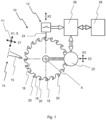
- FIG. 1 shows a schematic representation of a processing device 10 according to the invention, which has a clamping device which can be driven in rotation about an axis of rotation A, but is not shown in more detail. Furthermore, the processing device 10 has a measuring device 12 and a processing unit 14.
- the processing unit 14 has a processing tool 15, which is arranged on a slide arrangement, not shown, of the processing unit 14, the slide arrangement having a first linear slide, which enables the processing tool 15 to be linearly displaceable along a first slide direction X1, as well as a second linear slide, which enables the machining tool 15 to be moved linearly along a second slide direction Z1.
- the carriage arrangement can optionally also enable the machining tool 15 to be moved linearly along a third carriage direction Y1.
- the processing unit 14 also has a rotatably drivable spindle, through which the machining tool 15 can be rotatably driven on the slide arrangement about a spindle axis S, which in the present case coincides with the first slide direction X1.
- the machining tool 15 or the first slide direction X1 and the second slide direction Z1 are arranged inclined relative to a horizontal axis.
- the processing unit 14 has an inclination adjustment mechanism, not shown.
- the reclining mechanism may support the carriage assembly or vice versa.
- the spindle axis S and the first carriage direction X1 are not aligned orthogonally to a horizontal axis, but at an angle of approximately 13 degrees.
- the angle is only to be understood as an example.
- the angle can be a predetermined value to which a cutting edge is to be ground.
- a cutting tool 16 in the form of a circular saw blade is arranged on the clamping device and is firmly clamped.
- the cutting tool 16 has a plurality of teeth 18 with a predetermined, constant tooth spacing, with a cutting edge 20 to be machined being fixedly arranged on each tooth 18.
- the cutting edges 20 are made of a particularly hard material such as hardened steel, hard metal, polycrystalline diamond (PCD) or diamond-coated hard metal material.
- the clamping device is set up to firmly clamp or release the cutting tool.
- a controllable clamping mechanism can be provided.
- the clamping device has a rotary drive 22, which is designed to rotate the clamping device about the axis of rotation A.
- the axis of rotation A runs orthogonally to the image plane.
- the rotary drive 22 is set up to block rotation of the clamping device about the axis of rotation A.
- the rotary drive 22 is set up to detect an angular position of the clamping device about the axis of rotation A or to output it as a coded value.
- the clamping device can be designed as a clamping unit, which additionally comprises a clamping slide arrangement, which enables the rotary drive to be linearly displaceable relative to the rest of the processing device 10 or the processing unit 14 in at least a first clamping slide direction X3 and/or a second clamping slide direction Z3. At least one of the clamping carriage directions is then preferably arranged orthogonally to the axis of rotation A.
- the rotary drive 22 is shown schematically next to the axis of rotation A, but can also be arranged on the axis of rotation A.
- the measuring device 12 is arranged on a linear drive, not shown, which makes it possible to displace the measuring device 12 relative to the clamping device in a drive direction X2 that is orthogonal to the axis of rotation A.
- the measuring device 12 has a tactile, i.e. a touch-sensitive sensor 24.
- the sensor 24 is set up to contact one of the cutting edges 20 to be machined.
- the angular position i.e. the rotational position of the clamping device about the axis of rotation A
- the controller 26 is connected to all controllable or signaling components of the processing device 10, including the measuring device 12, the rotary drive 22 and the memory 28, via signal lines such as a bus system.
- Figure 2 shows a schematic representation of the method 100 according to the invention.
- the method 100 comprises several, successive steps a) to f).
- step a) the cutting tool 16 is clamped onto the clamping device. This can be done manually or automatically. A marking can be provided on the clamping device, which indicates how the cutting tool 16 should be clamped. Additionally or alternatively, the clamping device can be provided with a holder that allows the cutting tool 16 to be clamped only in a predetermined position on the clamping device.
- Step b) then takes place, in which an angular position of one of the cutting edges 20 to be machined is measured using the measuring device 12 as the actual position of this cutting edge 20 to be machined.
- the angular position describes a measured value relative to the axis of rotation A.
- the actual position can be stored in the memory 28 for the cutting edge 20 to be machined.
- the cutting edge 20 to be machined is first aligned relative to the measuring device 12, for example in a sub-step b1).
- the measuring device 12 is displaced in the direction of the drive direction X2.
- the clamping device is driven in rotation about the axis of rotation A.
- the measuring device 12 outputs a signal, after which the sensor 24 contacts or detects the cutting edge to be machined, the actual position of the cutting edge 20 to be machined is measured. This measurement can also be referred to as sub-step b3). After a respective measuring process or at the end of step d), the measuring device 12 can move in the drive direction X2 from the cutting edge 20 to be machined be removed so that the sensor 24 can no longer come into engagement with the cutting edge 20 to be machined.
- the measurement can be repeated for one or more points of the cutting edge 20 in order to detect a profile or inclination of the cutting edge 20 on the cutting tool 16.
- the profile or inclination can be measured as the actual position.
- step b) is repeated one after the other or by carrying out steps b) to f) until an angular position has been measured for all cutting edges to be machined or all cutting edges 20 to be machined have been sharpened.
- This is particularly advantageous when using an optical sensor such as a laser light barrier.
- the cutting tool 16 is rotated once by one revolution. Alternatively or additionally, after measuring a cutting edge on one diameter, it can be measured on at least one further diameter, for example to determine the rake angle of the cutting edge.
- step c) a deviation of the actual position from a target position of one cutting edge 20 to be machined or for all cutting edges 20 to be machined is determined.
- a predetermined value serves as the target position, which is known for the cutting tool 16 for each of the cutting edges 20 or has been defined in advance or results from a target position of a cutting edge for the other cutting edges.
- the respective cutting edge 20 to be processed is positioned in a processing position.
- the cutting tool 16 is driven in rotation about the axis of rotation A until the cutting edge 20 to be machined, for which the deviation was determined, reaches a predetermined rotational position.
- the processing position it is possible for the processing tool 15 to come into engagement with the cutting edge 20 to be processed in order to enable sharpening processing.
- the cutting edge 20 to be machined is pivoted into the machining position after measuring, provided that the measuring does not take place in the machining position.
- the machining position is a predetermined angle of rotation, in the extension of which the machining tool 15 is located.
- the cutting edge 20 reaches exactly the machining position, because after positioning, the machining position approached is known based on the measured actual position and the machining tool 15 can be moved by moving the axes X1 and / or Z1 in the direction of the approached Machining position can be moved.
- This is a decisive advantage compared to previous machines, which include a feed, for example.
- the current position of the cutting edge is not known and it is assuming that it is in the position in which the feeder positioned it. However, this can be inaccurate due to inertia, especially if the feed speed is too high, or due to friction in the clamping or deformations during clamping.
- Step d) is therefore optional because the processing unit 14 can also be arranged together with the measuring device 12. Then the processing tool 15 can come into engagement with the cutting edge 20 to be processed instead of the sensor 24.
- the rotational driving in step d) may depend on the angle at which the machining tool 15 is inclined.
- step d) If the deviation determined in step c) is above a predetermined limit value, which results, for example, from the positioning accuracy of the clamping device about the axis of rotation A, the deviation in step d) is at least partially compensated for by increasing or reducing the rotational movement about the axis of rotation A.
- the positioning can therefore be adjusted.
- the extent of the rotational driving can be increased or reduced in such a way that the cutting edge in the machining position achieves a deviation below the limit value.
- the extent of the correction may be adjusted depending on step d). It is therefore possible to use the method 100 according to the invention even with large deviations and still achieve a high level of machining accuracy.
- the angular position of the machining tool 15 does not have to be changed at least during the machining of a respective cutting tool 16. This reduces the processing effort and shortens the processing time for sharpening for the entire cutting tool 16.
- step e) the relative starting position of the machining tool 15 relative to the cutting edge 20 to be machined is corrected into a corrected relative starting position by linear displacement based on the determined deviation.
- the machining tool 15 is displaced linearly using the carriage arrangement.
- the machining tool 15 can be displaced, for example, in the first slide direction X1 or in the second slide direction X2.
- the cutting tool 16 can be displaced by means of the clamping slide arrangement in one of its slide directions, for example in the first clamping slide direction X3 and/or second clamping slide direction Z3. This takes place depending on the specific deviation and possibly also depending on the angle or inclination of the processing tool 15.
- step f) the cutting edge 20 to be machined is sharpened using the machining tool 15, starting from the corrected starting position. Grinding or erosion machining can take place, depending on the design of the machining tool 15.
- the grinding is carried out using a predetermined movement pattern of the machining tool 15, which is generated by the carriage arrangement of the machining unit 14. Furthermore, the machining tool 15 is driven in rotation about the spindle axis S.
- the predetermined movement pattern includes at least one movement of the processing tool 15 along the second carriage direction Z1.
- the movement pattern can also include a movement of the machining tool 15 in the first carriage direction X1 and/or a third carriage direction Y1.
- the carriage directions X1, Z1 and Y1 are aligned orthogonally to each other.
- the movement pattern may include a meandering shape, a spiral shape and/or a one-dimensional movement shape.
- the correcting step does not or cannot completely compensate for the deviation.
- An angular error can therefore occur, for example in the rake face of the cutting edge to be machined.
- this is extremely low or can be neglected in favor of a simple and quick process.
Landscapes
- Engineering & Computer Science (AREA)
- Mechanical Engineering (AREA)
- Human Computer Interaction (AREA)
- Manufacturing & Machinery (AREA)
- Physics & Mathematics (AREA)
- General Physics & Mathematics (AREA)
- Automation & Control Theory (AREA)
- Automatic Control Of Machine Tools (AREA)
Applications Claiming Priority (1)
| Application Number | Priority Date | Filing Date | Title |
|---|---|---|---|
| DE102022114020.2A DE102022114020A1 (de) | 2022-06-02 | 2022-06-02 | Verfahren und Bearbeitungsvorrichtung zum Schärfbearbeiten von Schneiden eines rotativen Schneidwerkzeugs |
Publications (2)
| Publication Number | Publication Date |
|---|---|
| EP4286094A1 true EP4286094A1 (fr) | 2023-12-06 |
| EP4286094B1 EP4286094B1 (fr) | 2026-04-29 |
Family
ID=86688416
Family Applications (1)
| Application Number | Title | Priority Date | Filing Date |
|---|---|---|---|
| EP23176917.5A Active EP4286094B1 (fr) | 2022-06-02 | 2023-06-02 | Procédé et dispositif d'usinage pour l'affûtage de lames d'un outil de coupe rotatif |
Country Status (2)
| Country | Link |
|---|---|
| EP (1) | EP4286094B1 (fr) |
| DE (1) | DE102022114020A1 (fr) |
Cited By (1)
| Publication number | Priority date | Publication date | Assignee | Title |
|---|---|---|---|---|
| CN119217161A (zh) * | 2024-11-28 | 2024-12-31 | 广东欧欧优家居有限公司 | 一种用于刀具磨削的控制方法及系统 |
Citations (4)
| Publication number | Priority date | Publication date | Assignee | Title |
|---|---|---|---|---|
| US4819515A (en) * | 1987-06-26 | 1989-04-11 | Armstrong Manufacturing Company | Method and apparatus for grinding saw teeth |
| DE19752140A1 (de) | 1996-12-04 | 1998-06-10 | Franco Accorsi | Verfahren und Maschine zum Schärfen und Profilieren von rotierenden Werkzeugen mit aufgelöteten oder aufgeschweißten Einsatzzähnen |
| FR2774614A3 (fr) * | 1998-02-06 | 1999-08-13 | Ake Knebel Gmbh & Co | Procede et dispositif de rectification des faces actives des dents d'un outil de sciage |
| US6379218B1 (en) * | 1997-10-01 | 2002-04-30 | Vollmer Werke Maschinenfabrik Gmbh | Machine for machining workpieces with cutting teeth, especially saw blades |
Family Cites Families (2)
| Publication number | Priority date | Publication date | Assignee | Title |
|---|---|---|---|---|
| DE20108796U1 (de) | 2001-05-18 | 2002-01-10 | RECORD Maschinenbau GmbH, 07426 Königsee | Vorrichtung zum Schärfen von Sägezahnkonturen an HSS-, Vollhartmetall- und hartmetallbestückten Kreissägeblättern |
| DE102006002282A1 (de) | 2005-01-24 | 2006-07-27 | Iseli & Co. Ag Maschinenfabrik | Verfahren und Vorrichtung zum Schleifen von Kreissägeblättern |
-
2022
- 2022-06-02 DE DE102022114020.2A patent/DE102022114020A1/de active Pending
-
2023
- 2023-06-02 EP EP23176917.5A patent/EP4286094B1/fr active Active
Patent Citations (4)
| Publication number | Priority date | Publication date | Assignee | Title |
|---|---|---|---|---|
| US4819515A (en) * | 1987-06-26 | 1989-04-11 | Armstrong Manufacturing Company | Method and apparatus for grinding saw teeth |
| DE19752140A1 (de) | 1996-12-04 | 1998-06-10 | Franco Accorsi | Verfahren und Maschine zum Schärfen und Profilieren von rotierenden Werkzeugen mit aufgelöteten oder aufgeschweißten Einsatzzähnen |
| US6379218B1 (en) * | 1997-10-01 | 2002-04-30 | Vollmer Werke Maschinenfabrik Gmbh | Machine for machining workpieces with cutting teeth, especially saw blades |
| FR2774614A3 (fr) * | 1998-02-06 | 1999-08-13 | Ake Knebel Gmbh & Co | Procede et dispositif de rectification des faces actives des dents d'un outil de sciage |
Cited By (2)
| Publication number | Priority date | Publication date | Assignee | Title |
|---|---|---|---|---|
| CN119217161A (zh) * | 2024-11-28 | 2024-12-31 | 广东欧欧优家居有限公司 | 一种用于刀具磨削的控制方法及系统 |
| CN119217161B (zh) * | 2024-11-28 | 2025-03-11 | 广东欧欧优家居有限公司 | 一种用于刀具磨削的控制方法及系统 |
Also Published As
| Publication number | Publication date |
|---|---|
| EP4286094B1 (fr) | 2026-04-29 |
| DE102022114020A1 (de) | 2023-12-07 |
Similar Documents
| Publication | Publication Date | Title |
|---|---|---|
| EP1719585B1 (fr) | Machine destinée au traitement de pièces optiques, nominalement de verres de lunettes en plastique | |
| DE102014111402B4 (de) | Bearbeitungsverfahren mit einem Schneidwerkzeug und Drahtelektroerosionsvorrichtung | |
| DE69901004T2 (de) | Verfahren und vorrichtung zur bearbeitung von vorbearbeiteten, verzahnten werkstücken wie zahnräder | |
| DE19910747B9 (de) | Verfahren und Vorrichtung zum Einmitten eines Abrichtwerkzeuges in die Ganglücke einer Schleifschnecke | |
| EP1588224B1 (fr) | Procede et dispositif de fabrication d'aubes de service | |
| EP2394783B1 (fr) | Meuleuse cylindrique sans pointe et procédé de meulage sans pointe à l'aide d'une plaque de réglage réglable en hauteur | |
| WO2019115332A1 (fr) | Procédé et dispositif servant à mesurer un outil d'usinage par laminage | |
| DE2346796A1 (de) | Automatisches richtverfahren und richtmaschine dafuer mit mehreren richtstellen | |
| DE102012002126A1 (de) | Verfahren zur Ansteuerung der Bewegung eines Abrichtwerkzeugs | |
| DE102018118031A1 (de) | Bearbeitungsvorrichtung und Verfahren zur Bearbeitung | |
| DE102012201732B4 (de) | Numerisch gesteuerte Werkzeugmaschine und Verfahren zum Steuern eines automatischen rotatorischen Ausrichtvorgangs eines Zahnrads an der Werkzeugmaschine | |
| DE3119629A1 (de) | Verfahren zum spannen und positionieren von praezisionsteilen | |
| WO1998004379A1 (fr) | Machine a usiner des pieces avec des dents de coupe, notamment des lames de scie | |
| EP4286094A1 (fr) | Procédé et dispositif d'usinage pour l'affûtage de lames d'un outil de coupe rotatif | |
| EP0252090B1 (fr) | Procede et dispositif pour la mise a zero d'une rectifieuse cylindrique | |
| EP3711900A1 (fr) | Dispositif et procédé d'usinage de pièces similaires | |
| DE19804762B4 (de) | Verfahren und Vorrichtung zum Schleifen der Frei-, Span- und/oder Brustfläche von Zähnen eines Sägewerkzeugs | |
| DE2931845A1 (de) | Kopierfraesmaschine | |
| DE19738818B4 (de) | Verfahren und Vorrichtung zur formgeregelten Feinstbearbeitung eines Werkstücks | |
| DE69712222T2 (de) | Verfahren zur steuerung einer werkzeugmaschine | |
| EP3596563B1 (fr) | Procédé d'usinage de pièces avec un centre d'usinage | |
| EP3325202B1 (fr) | Procédé et dispositif d'usinage de finition de chaises de palier pré-usinées des paliers principaux et des paliers mobiles de vilebrequins | |
| DE10142739B4 (de) | Maschine zum Hinterarbeiten eines um eine Drehachse rotierenden Werkstücks | |
| DE102016224871A1 (de) | Verfahren zum Betreiben einer Mehrachs-Drehmaschine und Mehrachs-Drehmaschine | |
| DE10354622B4 (de) | Verfahren und Vorrichtung zum Herstellen einer Gewinderolle |
Legal Events
| Date | Code | Title | Description |
|---|---|---|---|
| PUAI | Public reference made under article 153(3) epc to a published international application that has entered the european phase |
Free format text: ORIGINAL CODE: 0009012 |
|
| STAA | Information on the status of an ep patent application or granted ep patent |
Free format text: STATUS: REQUEST FOR EXAMINATION WAS MADE |
|
| 17P | Request for examination filed |
Effective date: 20230602 |
|
| AK | Designated contracting states |
Kind code of ref document: A1 Designated state(s): AL AT BE BG CH CY CZ DE DK EE ES FI FR GB GR HR HU IE IS IT LI LT LU LV MC ME MK MT NL NO PL PT RO RS SE SI SK SM TR |
|
| GRAP | Despatch of communication of intention to grant a patent |
Free format text: ORIGINAL CODE: EPIDOSNIGR1 |
|
| STAA | Information on the status of an ep patent application or granted ep patent |
Free format text: STATUS: GRANT OF PATENT IS INTENDED |
|
| RIC1 | Information provided on ipc code assigned before grant |
Ipc: B24B 3/46 20060101AFI20251201BHEP Ipc: G05B 99/00 20060101ALI20251201BHEP Ipc: B23D 63/12 20060101ALI20251201BHEP Ipc: B23D 63/00 20060101ALI20251201BHEP Ipc: B24B 51/00 20060101ALI20251201BHEP Ipc: B24B 49/04 20060101ALI20251201BHEP Ipc: B23D 63/14 20060101ALI20251201BHEP Ipc: G05B 19/402 20060101ALI20251201BHEP |
|
| INTG | Intention to grant announced |
Effective date: 20251218 |
|
| GRAS | Grant fee paid |
Free format text: ORIGINAL CODE: EPIDOSNIGR3 |
|
| GRAA | (expected) grant |
Free format text: ORIGINAL CODE: 0009210 |
|
| STAA | Information on the status of an ep patent application or granted ep patent |
Free format text: STATUS: THE PATENT HAS BEEN GRANTED |