EP4286128A1 - Appareil et procédé de traitement de matériau dans une trémie - Google Patents
Appareil et procédé de traitement de matériau dans une trémie Download PDFInfo
- Publication number
- EP4286128A1 EP4286128A1 EP23174837.7A EP23174837A EP4286128A1 EP 4286128 A1 EP4286128 A1 EP 4286128A1 EP 23174837 A EP23174837 A EP 23174837A EP 4286128 A1 EP4286128 A1 EP 4286128A1
- Authority
- EP
- European Patent Office
- Prior art keywords
- process fluid
- internal volume
- incoherent
- plastics
- permeable
- Prior art date
- Legal status (The legal status is an assumption and is not a legal conclusion. Google has not performed a legal analysis and makes no representation as to the accuracy of the status listed.)
- Granted
Links
Images


Classifications
-
- B—PERFORMING OPERATIONS; TRANSPORTING
- B29—WORKING OF PLASTICS; WORKING OF SUBSTANCES IN A PLASTIC STATE IN GENERAL
- B29B—PREPARATION OR PRETREATMENT OF THE MATERIAL TO BE SHAPED; MAKING GRANULES OR PREFORMS; RECOVERY OF PLASTICS OR OTHER CONSTITUENTS OF WASTE MATERIAL CONTAINING PLASTICS
- B29B13/00—Conditioning or physical treatment of the material to be shaped
- B29B13/02—Conditioning or physical treatment of the material to be shaped by heating
-
- B—PERFORMING OPERATIONS; TRANSPORTING
- B29—WORKING OF PLASTICS; WORKING OF SUBSTANCES IN A PLASTIC STATE IN GENERAL
- B29B—PREPARATION OR PRETREATMENT OF THE MATERIAL TO BE SHAPED; MAKING GRANULES OR PREFORMS; RECOVERY OF PLASTICS OR OTHER CONSTITUENTS OF WASTE MATERIAL CONTAINING PLASTICS
- B29B13/00—Conditioning or physical treatment of the material to be shaped
- B29B13/06—Conditioning or physical treatment of the material to be shaped by drying
- B29B13/065—Conditioning or physical treatment of the material to be shaped by drying of powder or pellets
-
- F—MECHANICAL ENGINEERING; LIGHTING; HEATING; WEAPONS; BLASTING
- F26—DRYING
- F26B—DRYING SOLID MATERIALS OR OBJECTS BY REMOVING LIQUID THEREFROM
- F26B17/00—Machines or apparatus for drying materials in loose, plastic, or fluidised form, e.g. granules, staple fibres, with progressive movement
- F26B17/12—Machines or apparatus for drying materials in loose, plastic, or fluidised form, e.g. granules, staple fibres, with progressive movement with movement performed solely by gravity, i.e. the material moving through a substantially vertical drying enclosure, e.g. shaft
- F26B17/14—Machines or apparatus for drying materials in loose, plastic, or fluidised form, e.g. granules, staple fibres, with progressive movement with movement performed solely by gravity, i.e. the material moving through a substantially vertical drying enclosure, e.g. shaft the materials moving through a counter-current of gas
- F26B17/1408—Machines or apparatus for drying materials in loose, plastic, or fluidised form, e.g. granules, staple fibres, with progressive movement with movement performed solely by gravity, i.e. the material moving through a substantially vertical drying enclosure, e.g. shaft the materials moving through a counter-current of gas the gas being supplied and optionally extracted through ducts extending into the moving stack of material
- F26B17/1425—Machines or apparatus for drying materials in loose, plastic, or fluidised form, e.g. granules, staple fibres, with progressive movement with movement performed solely by gravity, i.e. the material moving through a substantially vertical drying enclosure, e.g. shaft the materials moving through a counter-current of gas the gas being supplied and optionally extracted through ducts extending into the moving stack of material the ducts being perforated and arranged vertically
-
- F—MECHANICAL ENGINEERING; LIGHTING; HEATING; WEAPONS; BLASTING
- F26—DRYING
- F26B—DRYING SOLID MATERIALS OR OBJECTS BY REMOVING LIQUID THEREFROM
- F26B25/00—Details of general application not covered by group F26B21/00 or F26B23/00
- F26B25/005—Treatment of dryer exhaust gases
- F26B25/007—Dust filtering; Exhaust dust filters
-
- F—MECHANICAL ENGINEERING; LIGHTING; HEATING; WEAPONS; BLASTING
- F26—DRYING
- F26B—DRYING SOLID MATERIALS OR OBJECTS BY REMOVING LIQUID THEREFROM
- F26B3/00—Drying solid materials or objects by processes involving the application of heat
- F26B3/02—Drying solid materials or objects by processes involving the application of heat by convection, i.e. heat being conveyed from a heat source to the materials or objects to be dried by a gas or vapour, e.g. air
- F26B3/06—Drying solid materials or objects by processes involving the application of heat by convection, i.e. heat being conveyed from a heat source to the materials or objects to be dried by a gas or vapour, e.g. air the gas or vapour flowing through the materials or objects to be dried
-
- F—MECHANICAL ENGINEERING; LIGHTING; HEATING; WEAPONS; BLASTING
- F26—DRYING
- F26B—DRYING SOLID MATERIALS OR OBJECTS BY REMOVING LIQUID THEREFROM
- F26B21/00—Arrangements for supplying or controlling air or other gases for drying solid materials or objects
- F26B21/20—Circulating air or gases in closed cycles, e.g. wholly within the drying enclosure
- F26B21/25—Circulating air or gases in closed cycles, e.g. wholly within the drying enclosure partly outside the drying enclosure
-
- F—MECHANICAL ENGINEERING; LIGHTING; HEATING; WEAPONS; BLASTING
- F26—DRYING
- F26B—DRYING SOLID MATERIALS OR OBJECTS BY REMOVING LIQUID THEREFROM
- F26B21/00—Arrangements for supplying or controlling air or other gases for drying solid materials or objects
- F26B21/30—Controlling, e.g. regulating, parameters of gas supply
- F26B21/33—Humidity
-
- F—MECHANICAL ENGINEERING; LIGHTING; HEATING; WEAPONS; BLASTING
- F26—DRYING
- F26B—DRYING SOLID MATERIALS OR OBJECTS BY REMOVING LIQUID THEREFROM
- F26B2200/00—Drying processes and machines for solid materials characterised by the specific requirements of the drying goods
- F26B2200/08—Granular materials
Definitions
- the invention relates to an apparatus for processing material in a hopper, in particular for processing incoherent plastics, i.e. in the form of granules and/or microgranules and/or pellets and/or powder and/or flakes or the like.
- a process fluid generally hot air
- a process fluid generally hot air
- the invention can be advantageously applied in the context of a plant for treating incoherent plastics, like, for example, a plant for dehumidifying and/or drying and/or crystallizing and/or packaging and/or conveying in a vacuum and/or under pressure the incoherent plastics.
- This plant may be intended, in particular, to supply a user machine, such as, for example, a machine for processing and transforming plastics, in particular an extruder that supplies extruded plastics to an injection moulding and/or blow moulding and/or compression moulding apparatus.
- Patent publication US 2009/090019 A1 shows an apparatus according to the preamble of claim 1.
- Patent publication US 2021/0387380 A1 shows a solution intended to obtain a better distribution of thermal energy in the mass of the polymer granules and to reduce energy consumption.
- This solution diffuses the process fluid (hot air) inside a drying and/or dehumidifying hopper not only vertically (in general from bottom to top), but also horizontally.
- This combined mode involves the use of a great flowrate of the process fluid to ensure the transmission of the thermal energy to the granule. It has been established that this flowrate is about double the flowrate in a traditional process that uses a distributing cone that distributes in a vertical manner.
- One object of the invention is to provide an apparatus and/or a method that is able to overcome the aforesaid limits and drawbacks of the prior art.
- One object is to provide a solution, which is alternative to the prior art solutions, for processing incoherent plastics.
- One advantage is to reduce the phenomenon of conveying the granule to a hopper and/or optimizing the distribution of the air inside the hopper.
- One advantage is to limit the material conveyed "in flight" by the process fluid and reduce clogging of the filters of the fluid.
- One advantage is to transmit thermal energy to the granule so as to homogenize the temperature of the granule and reduce the thermal gradient between the heart of the granule and the external surface thereof.
- One advantage is to reduce or eliminate the powder deposit (coming from the granule) along the conduits evacuating the process fluid.
- One advantage is to obtain high process efficiency, in particular of a process that involves heating material.
- One advantage is to make available a constructionally simple and cheap apparatus for processing incoherent plastics.
- a method for processing incoherent plastics with a process fluid comprises the step of generating a flow of the process fluid through the incoherent plastics contained in an internal volume of a container and the step of extracting the process fluid through at least one tubular portion, which is permeable to the process fluid, of at least one tubular body that is provided above with an opening that leads into an outlet chamber of the process fluid that is arranged above the internal volume and is separated from the internal volume by a diaphragm that is impermeable to the process fluid.
- the method may comprise the step of introducing the incoherent plastics into the internal volume through at least one inlet port separated from the outlet chamber by separating means that is impermeable to the process fluid.
- a method for processing incoherent plastics with a process fluid comprises the step of generating a flow of the process fluid through the incoherent plastics contained in an internal volume of a container and the step of extracting the process fluid through at least one tubular portion, which is permeable to the process fluid, of at least one tubular body that is provided above with an opening connected to an outlet of the process fluid, in which the aforesaid at least one tubular body may be, in particular, arranged eccentrically with respect to a vertical central longitudinal axis of the aforesaid container.
- tubular bodies each comprising at least one tubular portion which is permeable to the process fluid and at least one upper opening connected to the outlet, arranged angularly spaced apart with respect to a vertical central longitudinal axis of the aforesaid container.
- permeable to the process fluid means a means (for example a perforated wall) that lets the process fluid pass through and retains the incoherent material or at least the less fine particles.
- the only escape route for the incoherent plastics to the outlet chamber consists of each of the aforesaid tubular portions that are permeable to the fluid that advantageously represent a significantly effective barrier against the undesired aspiration of incoherent plastics.
- tubular bodies immersed in the internal volume of the container of the incoherent plastics enables the transit surface of the process fluid to be increased. It is further observed that the tubular bodies can be completely surrounded by the incoherent plastics, when the internal volume is sufficiently filled, so that flowing of the material contributes to keeping the surfaces of the tubular bodies clean by eliminating the depositing of powder.
- the eccentric arrangement with respect to a central axis of the container of one, two or more tubular bodies enables the material to be limited that is conveyed "in flight" by the process fluid and also obtains the advantage of reducing clogging of the filters by the material conveyed.
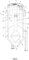
- the apparatus 1 comprises a container 2 extending vertically with an internal volume configured to contain the incoherent plastics.
- the container 2 may comprise, in particular, a drying and/or dehumidifying hopper for drying and/or dehumidifying incoherent plastics (polymer granules).
- the container 2 may comprise, in particular, a vertical central longitudinal axis.
- the apparatus 1 may comprise, in particular, an outlet chamber 3 of the process fluid arranged above the internal volume containing the material.
- the outlet chamber 3 is provided with at least one outlet 4 of the process fluid.
- the outlet chamber 3 may be, in particular, separated from the internal volume, where the plastics are situated, by a diaphragm 5 (for example made of sheet metal) that is permeable to the process fluid.
- the diaphragm 5 is provided with one or more openings 6 to enable the process fluid to exit the internal volume.
- the apparatus 1 comprises, for each of the aforesaid openings 6, a tubular body 7 extending below the diaphragm 5 and arranged inside the internal volume.
- Each tubular body 7 is open above at the respective opening 6 in the diaphragm 5.
- Each tubular body 7 may comprise, in particular, at least one segment 7a that is permeable to the process fluid.
- This segment 7a that is permeable to the fluid may comprise, in particular, a tubular segment, for example a perforated tubular wall.
- This segment 7a that is permeable enables the process fluid to exit the internal volume through the respective opening.
- This segment 7a that is permeable may be, in particular, arranged in the internal volume so as to be completely immersed and surrounded (at 360° degrees) by the incoherent plastics that are processed once the internal volume has been sufficiently filled with the material.
- the apparatus 1 comprises means for generating a flow of the process fluid inside the internal volume to the outlet chamber 3.
- the means for generating a flow may comprise, in particular, at least one fan 8 to send the flow to an inlet 9 of the container 2.
- the means for generating a flow may comprise, in particular, at least one filter 10 for filtering the process fluid coming from the outlet 4 of the container. It is possible, as in the embodiment of Figure 1 , for the apparatus 1 to comprise a closed circuit for the circulation of the process fluid.
- the fan 8 may operate in a closed circuit by removing the fluid from the outlet 4 and sending the fluid to the inlet 9.
- the apparatus 1 may comprise, in particular, regenerating means, for example of known type (not illustrated), to regenerate the fluid exiting the container 2. The regenerated fluid may be sent in a closed circuit to the inlet 9 by the fan 8.
- the outlet chamber 3 may be, in particular, of annular shape.
- the outlet chamber 3 may be, in particular, internally bounded by a tubular wall 11 that is permeable to the process fluid.
- the tubular wall 11 may define, in particular, a passage for the entry of the incoherent plastics into the internal volume.
- the apparatus 1 may comprise, in particular, a loader 12 for feeding the incoherent plastics to the internal volume through the tubular wall 11. It is possible, as in the embodiments in Figures 2 and 3 , for the material supplied by the loader 12 to pass inside the tubular wall 11 remaining isolated from the flow of the process fluid that exits through the outlet chamber 3.
- the apparatus 1 may comprise, in particular, a discharge 13 for the processed material to exit.
- the discharge 13 may comprise, in particular, an outlet port arranged at the lower end of the internal volume.
- the diaphragm 5 may be, in particular, arranged radially around the tubular wall 11 starting from the tubular wall 11, so as to ensure substantial impermeability to the process fluid.
- the diaphragm 5 may comprise, in particular, a wall of annular shape with an edge inside a closed loop (for example, of circular shape) directly connected (substantially coincident with) to a lower end edge of the tubular wall 11.
- the aforesaid passage for the entry of the material and the aforesaid outlet chamber 3 of the fluid may be, in particular, separated from one another by the tubular wall 11, so that the outlet chamber 3 is substantially isolated, almost hermetically, from the course of the incoherent plastics, apart from the fluid communication represented by the permeable segment/s 7a.
- This fluid communication is anyway conformed and arranged so as to constitute an effective barrier to reduce or eliminate the undesired transit of incoherent material.
- Each tubular body 7 may, in particular, extend along a longitudinal (for example, vertical) axis not coinciding with a longitudinal axis (for example, vertical) along which the tubular wall 11 (for example of cylindrical shape) extends.
- the longitudinal axis of each tubular body 7 may be spaced apart from the longitudinal axis of the tubular wall 11.
- the tubular wall 11 may be arranged centrally with respect to a vertical central longitudinal axis of the container 2, or with respect to a center of gravity of the diaphragm 5, whereas each tubular body 7 may be arranged eccentrically with respect to the vertical central longitudinal axis of the container 2, or with respect to the center of gravity of the diaphragm 5.
- the apparatus 1 may comprise, in particular, an inlet conduit 14 of the process fluid that is connected to the inlet 9 and is arranged in the internal volume and is permeable to the process fluid.
- the inlet conduit 14 may, in particular, terminate below with a permeable portion 15 (for example, perforated) that is arranged to enable the process fluid to enter the internal volume.
- the permeable portion 15 may be, in particular, arranged below each of the tubular bodies 7, in particular below the segments 7a that are permeable of the tubular bodies 7.
- the permeable portion 15 may comprise, in particular, a distributing cone.
- the permeable portion 15 may be, in particular, arranged in a manner that is central or coaxial with respect to the vertical central longitudinal axis of the container 2.
- Each tubular body 7 may be, in particular, arranged in a manner that is eccentric or offset with respect to the permeable portion 15 and/or with respect to the vertical central longitudinal axis of the container 2. This eccentric or offset arrangement, together with the fact that the segment 7a that is permeable can be completely immersed and surrounded by the incoherent material, promotes the regularity and efficiency of the extraction of the process fluid from the internal volume of the container to the outlet 4.
- the diaphragm 5 may be, in particular, provided with two, or three, or four, or five, or more than five openings 6, with each of which a respective tubular body 7 is associated.
- the openings 6 may be arranged, in particular, spaced angularly apart from one another around a vertical axis of the container 2.
- the tubular body 7 may comprise a segment 7a (lower and/or tubular) that is permeable to the process fluid to enable the transit thereof from the outside inside the tubular body 7.
- the tubular body 7 may comprise, in particular, an (upper or lower) segment 7b that is impermeable to the process fluid.
- the segment 7b that is impermeable may be arranged (for example coaxially) above the segment 7a that is permeable.
- the segment 7a that is permeable (perforated) may be of cylindrical shape.
- the segment 7b that is impermeable (unperforated) may be of cylindrical shape.
- the (upper) segment 7b that is impermeable may extend, in particular, between the respective (lower) segment 7a that is permeable and the respective opening 6 on the diaphragm 5.
- a vertical length of the (upper) segment 7b that is impermeable may be, in particular, greater than a vertical length of the respective (lower) segment 7a that is permeable.
- the apparatus 1 may comprise, in particular, at least one perforated wall 16 which is permeable to the process fluid and arranged to bound laterally the internal volume and define an annular circulating zone of the process fluid.
- the apparatus 1 may comprise, in particular, at least one external wall 17 that is permeable to the process fluid to bound laterally and externally the aforesaid annular zone.
- the apparatus 1 may comprise, in particular, one or more septa 18 that are impermeable to the process fluid to divide the aforesaid annular zone into two or more compartments arranged one on top of the other.
- the aforesaid annular circulating zone of the process fluid promotes circulation with at least one component of the flow in a horizontal direction.
- the division into two or more compartments arranged one on top of the other promotes complex circulation in which the flow can enter and exit each compartment so as to be able to enter or exit each compartment so as to generate flow components in a horizontal direction radially outwards and several components of the flow in a horizontal direction radially inwards.
- the operation of the apparatus may actuate, in particular, a method for processing incoherent plastics with a process fluid, in particular to dry and/or dehumidify incoherent plastics.
- the method may comprise, in particular, the step of generating a flow of a process fluid through incoherent plastics contained in an internal volume of a container 2.
- the method may comprise, in particular, the step of extracting the process fluid from the internal volume through a tubular body 7 which is at least partially permeable (for example perforated) to the fluid and provided above with an opening 6 that leads into an outlet chamber 3 of the process fluid arranged above the internal volume and separated from the internal volume by a diaphragm 5 which is permeable to the process fluid.
- the method may comprise, in particular, the step of extracting the process fluid through two or more tubular bodies 7 (each of which is at least partially permeable to the fluid) that are arranged angularly spaced apart from one another around a central vertical axis of the container 2.
- the number N of removal zones may be chosen in function of the maximum flowrate of the process fluid and/or of the diameter/height ratio of the container 2 (hopper).
- the embodiments of Figs 2 and 3 differ from one another substantially through the number of removal or extraction zones for removing or extracting the process fluid, i.e. tubular bodies 7.
Landscapes
- Engineering & Computer Science (AREA)
- Mechanical Engineering (AREA)
- General Engineering & Computer Science (AREA)
- Life Sciences & Earth Sciences (AREA)
- Microbiology (AREA)
- Physics & Mathematics (AREA)
- Thermal Sciences (AREA)
- Processing And Handling Of Plastics And Other Materials For Molding In General (AREA)
Applications Claiming Priority (1)
| Application Number | Priority Date | Filing Date | Title |
|---|---|---|---|
| IT102022000011555A IT202200011555A1 (it) | 2022-05-31 | 2022-05-31 | Apparato e metodo per processare materiale in una tramoggia |
Publications (2)
| Publication Number | Publication Date |
|---|---|
| EP4286128A1 true EP4286128A1 (fr) | 2023-12-06 |
| EP4286128B1 EP4286128B1 (fr) | 2024-10-09 |
Family
ID=82943322
Family Applications (1)
| Application Number | Title | Priority Date | Filing Date |
|---|---|---|---|
| EP23174837.7A Active EP4286128B1 (fr) | 2022-05-31 | 2023-05-23 | Appareil et procédé de traitement de matériau dans une trémie |
Country Status (2)
| Country | Link |
|---|---|
| EP (1) | EP4286128B1 (fr) |
| IT (1) | IT202200011555A1 (fr) |
Citations (8)
| Publication number | Priority date | Publication date | Assignee | Title |
|---|---|---|---|---|
| DE4234696A1 (de) * | 1991-10-14 | 1993-05-06 | Koch, Werner, 7536 Ispringen, De | Vorrichtung zum trocknen von kunststoffschuettgut |
| DE102006024126A1 (de) * | 2006-05-22 | 2007-11-29 | Bühler AG | Kompakte Vorrichtung zur Trocknung kristallisierbarer Polymerpartikel |
| US20090090019A1 (en) | 2007-10-09 | 2009-04-09 | Renato Moretto | Granular material treatment unit having a heat-regeneration group |
| CN108973003A (zh) * | 2018-08-07 | 2018-12-11 | 安徽龙锐模塑有限公司 | 一种注塑机用烘料斗 |
| CN110671909A (zh) * | 2019-10-30 | 2020-01-10 | 太仓金昊达新材料有限公司 | 一种塑料粒子烘料机 |
| CN111589792A (zh) * | 2020-05-28 | 2020-08-28 | 合肥德捷节能环保科技有限公司 | 一种塑料母粒除尘、清洗与烘干一体装置 |
| CN112959541A (zh) * | 2021-03-26 | 2021-06-15 | 浙江方欣新材料有限公司 | 一种锦纶纤维的生产方法 |
| US20210387380A1 (en) | 2018-10-24 | 2021-12-16 | Stefan Bock | Method and device for the fast and efficient heating of plastic granulates for preparing for the processing in a plasticization |
-
2022
- 2022-05-31 IT IT102022000011555A patent/IT202200011555A1/it unknown
-
2023
- 2023-05-23 EP EP23174837.7A patent/EP4286128B1/fr active Active
Patent Citations (8)
| Publication number | Priority date | Publication date | Assignee | Title |
|---|---|---|---|---|
| DE4234696A1 (de) * | 1991-10-14 | 1993-05-06 | Koch, Werner, 7536 Ispringen, De | Vorrichtung zum trocknen von kunststoffschuettgut |
| DE102006024126A1 (de) * | 2006-05-22 | 2007-11-29 | Bühler AG | Kompakte Vorrichtung zur Trocknung kristallisierbarer Polymerpartikel |
| US20090090019A1 (en) | 2007-10-09 | 2009-04-09 | Renato Moretto | Granular material treatment unit having a heat-regeneration group |
| CN108973003A (zh) * | 2018-08-07 | 2018-12-11 | 安徽龙锐模塑有限公司 | 一种注塑机用烘料斗 |
| US20210387380A1 (en) | 2018-10-24 | 2021-12-16 | Stefan Bock | Method and device for the fast and efficient heating of plastic granulates for preparing for the processing in a plasticization |
| CN110671909A (zh) * | 2019-10-30 | 2020-01-10 | 太仓金昊达新材料有限公司 | 一种塑料粒子烘料机 |
| CN111589792A (zh) * | 2020-05-28 | 2020-08-28 | 合肥德捷节能环保科技有限公司 | 一种塑料母粒除尘、清洗与烘干一体装置 |
| CN112959541A (zh) * | 2021-03-26 | 2021-06-15 | 浙江方欣新材料有限公司 | 一种锦纶纤维的生产方法 |
Also Published As
| Publication number | Publication date |
|---|---|
| EP4286128B1 (fr) | 2024-10-09 |
| IT202200011555A1 (it) | 2023-12-01 |
Similar Documents
| Publication | Publication Date | Title |
|---|---|---|
| US4591324A (en) | Granulating apparatus | |
| US10006714B2 (en) | Apparatus for drying a material | |
| US2561392A (en) | Process and apparatus for treating solutions to recover and coat solid particles | |
| US4584366A (en) | Process for the crystallizing, drying and aftercondensation of polycondensates | |
| DK151128B (da) | Fremgangsmaade og apparat til behandling af pulveragtige eller kornede materialer | |
| FI82980B (fi) | Foerfarande och anordning foer avlaegsnande av vatten fraon partikelformigt material. | |
| WO2007124745A1 (fr) | Appareil d'agglomération et procédé de fabrication de particules agglomérées | |
| KR20070087076A (ko) | 일련의 원통형 챔버의 회전 유동층 장치 및 방법 | |
| JPWO1997024570A1 (ja) | 粉粒体の乾燥方法及び乾燥装置 | |
| US11913721B2 (en) | Apparatus, a bottom plate component and a method for drying bulk particulate material | |
| EP4286128B1 (fr) | Appareil et procédé de traitement de matériau dans une trémie | |
| EP1044044B1 (fr) | Procede et appareil servant a extraire un liquide d'une matiere particulaire | |
| EP3550242B1 (fr) | Appareil et procédé de séchage de matière particulaire en vrac | |
| EP4470742A1 (fr) | Appareil et procédé de traitement de matériau incohérent | |
| JP3126023B2 (ja) | 連続造粒・コーティング装置 | |
| PL204355B1 (pl) | Urządzenie do suszenia rozpyłowego | |
| WO2017092758A1 (fr) | Système de séchage de poudre avec agencement de nettoyage d'unité de filtre amélioré, et procédé pour nettoyer le système | |
| US20240269896A1 (en) | System and method for recovering plastic recycling material | |
| US789109A (en) | Apparatus for treating materials. | |
| WO2013020832A2 (fr) | Traitement de gélules | |
| US5338365A (en) | Apparatus for conditioning confectioners' sugar and the like | |
| US2733762A (en) | Spray drier | |
| CN112933665A (zh) | 用于高粘度流体的脱挥系统以及脱挥方法 | |
| GB2050182A (en) | Method of and apparatus for drying liquid suspensions or solution | |
| HU201689B (en) | Pneumatic mixer for bulkable materials |
Legal Events
| Date | Code | Title | Description |
|---|---|---|---|
| PUAI | Public reference made under article 153(3) epc to a published international application that has entered the european phase |
Free format text: ORIGINAL CODE: 0009012 |
|
| STAA | Information on the status of an ep patent application or granted ep patent |
Free format text: STATUS: REQUEST FOR EXAMINATION WAS MADE |
|
| 17P | Request for examination filed |
Effective date: 20231031 |
|
| AK | Designated contracting states |
Kind code of ref document: A1 Designated state(s): AL AT BE BG CH CY CZ DE DK EE ES FI FR GB GR HR HU IE IS IT LI LT LU LV MC ME MK MT NL NO PL PT RO RS SE SI SK SM TR |
|
| GRAP | Despatch of communication of intention to grant a patent |
Free format text: ORIGINAL CODE: EPIDOSNIGR1 |
|
| STAA | Information on the status of an ep patent application or granted ep patent |
Free format text: STATUS: GRANT OF PATENT IS INTENDED |
|
| RIC1 | Information provided on ipc code assigned before grant |
Ipc: F26B 17/12 20060101ALI20240417BHEP Ipc: F26B 3/14 20060101ALI20240417BHEP Ipc: F26B 3/06 20060101ALI20240417BHEP Ipc: B29B 13/06 20060101ALI20240417BHEP Ipc: B29B 13/02 20060101AFI20240417BHEP |
|
| INTG | Intention to grant announced |
Effective date: 20240430 |
|
| P01 | Opt-out of the competence of the unified patent court (upc) registered |
Free format text: CASE NUMBER: APP_42075/2024 Effective date: 20240716 |
|
| GRAS | Grant fee paid |
Free format text: ORIGINAL CODE: EPIDOSNIGR3 |
|
| GRAA | (expected) grant |
Free format text: ORIGINAL CODE: 0009210 |
|
| STAA | Information on the status of an ep patent application or granted ep patent |
Free format text: STATUS: THE PATENT HAS BEEN GRANTED |
|
| AK | Designated contracting states |
Kind code of ref document: B1 Designated state(s): AL AT BE BG CH CY CZ DE DK EE ES FI FR GB GR HR HU IE IS IT LI LT LU LV MC ME MK MT NL NO PL PT RO RS SE SI SK SM TR |
|
| REG | Reference to a national code |
Ref country code: CH Ref legal event code: EP |
|
| REG | Reference to a national code |
Ref country code: DE Ref legal event code: R096 Ref document number: 602023000690 Country of ref document: DE |
|
| REG | Reference to a national code |
Ref country code: IE Ref legal event code: FG4D |
|
| REG | Reference to a national code |
Ref country code: LT Ref legal event code: MG9D |
|
| REG | Reference to a national code |
Ref country code: NL Ref legal event code: MP Effective date: 20241009 |
|
| PG25 | Lapsed in a contracting state [announced via postgrant information from national office to epo] |
Ref country code: NL Free format text: LAPSE BECAUSE OF FAILURE TO SUBMIT A TRANSLATION OF THE DESCRIPTION OR TO PAY THE FEE WITHIN THE PRESCRIBED TIME-LIMIT Effective date: 20241009 |
|
| PG25 | Lapsed in a contracting state [announced via postgrant information from national office to epo] |
Ref country code: NL Free format text: LAPSE BECAUSE OF FAILURE TO SUBMIT A TRANSLATION OF THE DESCRIPTION OR TO PAY THE FEE WITHIN THE PRESCRIBED TIME-LIMIT Effective date: 20241009 |
|
| PG25 | Lapsed in a contracting state [announced via postgrant information from national office to epo] |
Ref country code: HR Free format text: LAPSE BECAUSE OF FAILURE TO SUBMIT A TRANSLATION OF THE DESCRIPTION OR TO PAY THE FEE WITHIN THE PRESCRIBED TIME-LIMIT Effective date: 20241009 Ref country code: IS Free format text: LAPSE BECAUSE OF FAILURE TO SUBMIT A TRANSLATION OF THE DESCRIPTION OR TO PAY THE FEE WITHIN THE PRESCRIBED TIME-LIMIT Effective date: 20250209 Ref country code: PT Free format text: LAPSE BECAUSE OF FAILURE TO SUBMIT A TRANSLATION OF THE DESCRIPTION OR TO PAY THE FEE WITHIN THE PRESCRIBED TIME-LIMIT Effective date: 20250210 |
|
| PG25 | Lapsed in a contracting state [announced via postgrant information from national office to epo] |
Ref country code: FI Free format text: LAPSE BECAUSE OF FAILURE TO SUBMIT A TRANSLATION OF THE DESCRIPTION OR TO PAY THE FEE WITHIN THE PRESCRIBED TIME-LIMIT Effective date: 20241009 |
|
| PG25 | Lapsed in a contracting state [announced via postgrant information from national office to epo] |
Ref country code: BG Free format text: LAPSE BECAUSE OF FAILURE TO SUBMIT A TRANSLATION OF THE DESCRIPTION OR TO PAY THE FEE WITHIN THE PRESCRIBED TIME-LIMIT Effective date: 20241009 |
|
| PG25 | Lapsed in a contracting state [announced via postgrant information from national office to epo] |
Ref country code: ES Free format text: LAPSE BECAUSE OF FAILURE TO SUBMIT A TRANSLATION OF THE DESCRIPTION OR TO PAY THE FEE WITHIN THE PRESCRIBED TIME-LIMIT Effective date: 20241009 |
|
| PG25 | Lapsed in a contracting state [announced via postgrant information from national office to epo] |
Ref country code: NO Free format text: LAPSE BECAUSE OF FAILURE TO SUBMIT A TRANSLATION OF THE DESCRIPTION OR TO PAY THE FEE WITHIN THE PRESCRIBED TIME-LIMIT Effective date: 20250109 |
|
| PG25 | Lapsed in a contracting state [announced via postgrant information from national office to epo] |
Ref country code: LV Free format text: LAPSE BECAUSE OF FAILURE TO SUBMIT A TRANSLATION OF THE DESCRIPTION OR TO PAY THE FEE WITHIN THE PRESCRIBED TIME-LIMIT Effective date: 20241009 Ref country code: GR Free format text: LAPSE BECAUSE OF FAILURE TO SUBMIT A TRANSLATION OF THE DESCRIPTION OR TO PAY THE FEE WITHIN THE PRESCRIBED TIME-LIMIT Effective date: 20250110 |
|
| PG25 | Lapsed in a contracting state [announced via postgrant information from national office to epo] |
Ref country code: PL Free format text: LAPSE BECAUSE OF FAILURE TO SUBMIT A TRANSLATION OF THE DESCRIPTION OR TO PAY THE FEE WITHIN THE PRESCRIBED TIME-LIMIT Effective date: 20241009 |
|
| PG25 | Lapsed in a contracting state [announced via postgrant information from national office to epo] |
Ref country code: RS Free format text: LAPSE BECAUSE OF FAILURE TO SUBMIT A TRANSLATION OF THE DESCRIPTION OR TO PAY THE FEE WITHIN THE PRESCRIBED TIME-LIMIT Effective date: 20250109 |
|
| PG25 | Lapsed in a contracting state [announced via postgrant information from national office to epo] |
Ref country code: SM Free format text: LAPSE BECAUSE OF FAILURE TO SUBMIT A TRANSLATION OF THE DESCRIPTION OR TO PAY THE FEE WITHIN THE PRESCRIBED TIME-LIMIT Effective date: 20241009 |
|
| PGFP | Annual fee paid to national office [announced via postgrant information from national office to epo] |
Ref country code: DE Payment date: 20250529 Year of fee payment: 3 |
|
| PG25 | Lapsed in a contracting state [announced via postgrant information from national office to epo] |
Ref country code: DK Free format text: LAPSE BECAUSE OF FAILURE TO SUBMIT A TRANSLATION OF THE DESCRIPTION OR TO PAY THE FEE WITHIN THE PRESCRIBED TIME-LIMIT Effective date: 20241009 |
|
| REG | Reference to a national code |
Ref country code: DE Ref legal event code: R097 Ref document number: 602023000690 Country of ref document: DE |
|
| PGFP | Annual fee paid to national office [announced via postgrant information from national office to epo] |
Ref country code: IT Payment date: 20250531 Year of fee payment: 3 |
|
| PG25 | Lapsed in a contracting state [announced via postgrant information from national office to epo] |
Ref country code: EE Free format text: LAPSE BECAUSE OF FAILURE TO SUBMIT A TRANSLATION OF THE DESCRIPTION OR TO PAY THE FEE WITHIN THE PRESCRIBED TIME-LIMIT Effective date: 20241009 |
|
| PG25 | Lapsed in a contracting state [announced via postgrant information from national office to epo] |
Ref country code: RO Free format text: LAPSE BECAUSE OF FAILURE TO SUBMIT A TRANSLATION OF THE DESCRIPTION OR TO PAY THE FEE WITHIN THE PRESCRIBED TIME-LIMIT Effective date: 20241009 |
|
| PGFP | Annual fee paid to national office [announced via postgrant information from national office to epo] |
Ref country code: AT Payment date: 20250721 Year of fee payment: 3 |
|
| PG25 | Lapsed in a contracting state [announced via postgrant information from national office to epo] |
Ref country code: SK Free format text: LAPSE BECAUSE OF FAILURE TO SUBMIT A TRANSLATION OF THE DESCRIPTION OR TO PAY THE FEE WITHIN THE PRESCRIBED TIME-LIMIT Effective date: 20241009 |
|
| PG25 | Lapsed in a contracting state [announced via postgrant information from national office to epo] |
Ref country code: CZ Free format text: LAPSE BECAUSE OF FAILURE TO SUBMIT A TRANSLATION OF THE DESCRIPTION OR TO PAY THE FEE WITHIN THE PRESCRIBED TIME-LIMIT Effective date: 20241009 |
|
| PLBE | No opposition filed within time limit |
Free format text: ORIGINAL CODE: 0009261 |
|
| STAA | Information on the status of an ep patent application or granted ep patent |
Free format text: STATUS: NO OPPOSITION FILED WITHIN TIME LIMIT |
|
| PG25 | Lapsed in a contracting state [announced via postgrant information from national office to epo] |
Ref country code: SE Free format text: LAPSE BECAUSE OF FAILURE TO SUBMIT A TRANSLATION OF THE DESCRIPTION OR TO PAY THE FEE WITHIN THE PRESCRIBED TIME-LIMIT Effective date: 20241009 |
|
| 26N | No opposition filed |
Effective date: 20250710 |
|
| PG25 | Lapsed in a contracting state [announced via postgrant information from national office to epo] |
Ref country code: LU Free format text: LAPSE BECAUSE OF NON-PAYMENT OF DUE FEES Effective date: 20250523 |
|
| REG | Reference to a national code |
Ref country code: BE Ref legal event code: MM Effective date: 20250531 |
|
| PG25 | Lapsed in a contracting state [announced via postgrant information from national office to epo] |
Ref country code: MC Free format text: LAPSE BECAUSE OF FAILURE TO SUBMIT A TRANSLATION OF THE DESCRIPTION OR TO PAY THE FEE WITHIN THE PRESCRIBED TIME-LIMIT Effective date: 20241009 |
|
| REG | Reference to a national code |
Ref country code: AT Ref legal event code: UEP Ref document number: 1730100 Country of ref document: AT Kind code of ref document: T Effective date: 20241009 |
|
| PG25 | Lapsed in a contracting state [announced via postgrant information from national office to epo] |
Ref country code: IE Free format text: LAPSE BECAUSE OF NON-PAYMENT OF DUE FEES Effective date: 20250523 |
|
| PG25 | Lapsed in a contracting state [announced via postgrant information from national office to epo] |
Ref country code: BE Free format text: LAPSE BECAUSE OF NON-PAYMENT OF DUE FEES Effective date: 20250531 |
|
| PG25 | Lapsed in a contracting state [announced via postgrant information from national office to epo] |
Ref country code: FR Free format text: LAPSE BECAUSE OF NON-PAYMENT OF DUE FEES Effective date: 20250531 |