EP4286172A2 - Procédé et système pour produire un relief sur un substrat - Google Patents
Procédé et système pour produire un relief sur un substrat Download PDFInfo
- Publication number
- EP4286172A2 EP4286172A2 EP23203072.6A EP23203072A EP4286172A2 EP 4286172 A2 EP4286172 A2 EP 4286172A2 EP 23203072 A EP23203072 A EP 23203072A EP 4286172 A2 EP4286172 A2 EP 4286172A2
- Authority
- EP
- European Patent Office
- Prior art keywords
- relief
- coating
- sublimation
- product
- substrate
- Prior art date
- Legal status (The legal status is an assumption and is not a legal conclusion. Google has not performed a legal analysis and makes no representation as to the accuracy of the status listed.)
- Pending
Links
Images


Classifications
-
- B—PERFORMING OPERATIONS; TRANSPORTING
- B44—DECORATIVE ARTS
- B44C—PRODUCING DECORATIVE EFFECTS; MOSAICS; TARSIA WORK; PAPERHANGING
- B44C1/00—Processes, not specifically provided for elsewhere, for producing decorative surface effects
- B44C1/22—Removing surface-material, e.g. by engraving, by etching
-
- B—PERFORMING OPERATIONS; TRANSPORTING
- B41—PRINTING; LINING MACHINES; TYPEWRITERS; STAMPS
- B41M—PRINTING, DUPLICATING, MARKING, OR COPYING PROCESSES; COLOUR PRINTING
- B41M3/00—Printing processes to produce particular kinds of printed work, e.g. patterns
-
- B—PERFORMING OPERATIONS; TRANSPORTING
- B41—PRINTING; LINING MACHINES; TYPEWRITERS; STAMPS
- B41M—PRINTING, DUPLICATING, MARKING, OR COPYING PROCESSES; COLOUR PRINTING
- B41M5/00—Duplicating or marking methods; Sheet materials for use therein
- B41M5/0041—Digital printing on surfaces other than ordinary paper
- B41M5/0047—Digital printing on surfaces other than ordinary paper by ink-jet printing
-
- B—PERFORMING OPERATIONS; TRANSPORTING
- B44—DECORATIVE ARTS
- B44C—PRODUCING DECORATIVE EFFECTS; MOSAICS; TARSIA WORK; PAPERHANGING
- B44C3/00—Processes, not specifically provided for elsewhere, for producing ornamental structures
- B44C3/02—Superimposing layers
- B44C3/025—Superimposing layers to produce ornamental relief structures
-
- B—PERFORMING OPERATIONS; TRANSPORTING
- B44—DECORATIVE ARTS
- B44C—PRODUCING DECORATIVE EFFECTS; MOSAICS; TARSIA WORK; PAPERHANGING
- B44C5/00—Processes for producing special ornamental bodies
- B44C5/04—Ornamental plaques, e.g. decorative panels, decorative veneers
-
- B—PERFORMING OPERATIONS; TRANSPORTING
- B44—DECORATIVE ARTS
- B44F—SPECIAL DESIGNS OR PICTURES
- B44F9/00—Designs imitating natural patterns
- B44F9/02—Designs imitating natural patterns wood grain effects
-
- B—PERFORMING OPERATIONS; TRANSPORTING
- B44—DECORATIVE ARTS
- B44F—SPECIAL DESIGNS OR PICTURES
- B44F9/00—Designs imitating natural patterns
- B44F9/04—Designs imitating natural patterns of stone surfaces, e.g. marble
-
- B—PERFORMING OPERATIONS; TRANSPORTING
- B41—PRINTING; LINING MACHINES; TYPEWRITERS; STAMPS
- B41M—PRINTING, DUPLICATING, MARKING, OR COPYING PROCESSES; COLOUR PRINTING
- B41M5/00—Duplicating or marking methods; Sheet materials for use therein
- B41M5/0023—Digital printing methods characterised by the inks used
-
- E—FIXED CONSTRUCTIONS
- E04—BUILDING
- E04F—FINISHING WORK ON BUILDINGS, e.g. STAIRS, FLOORS
- E04F15/00—Flooring
- E04F15/02—Flooring or floor layers composed of a number of similar elements
- E04F15/10—Flooring or floor layers composed of a number of similar elements of other materials, e.g. fibrous or chipped materials, organic plastics, magnesite tiles, hardboard, or with a top layer of other materials
- E04F15/107—Flooring or floor layers composed of a number of similar elements of other materials, e.g. fibrous or chipped materials, organic plastics, magnesite tiles, hardboard, or with a top layer of other materials composed of several layers, e.g. sandwich panels
Definitions
- the present invention relates to methods and a systems for producing a 3D surface relief or structure on a substrate, in particular by means of digital inkjet printing, and particularly to a decorative or functional layer applicable on said substrate.
- the invention is particularly applicable in the field of the manufacture of products for construction and furniture, such as panels for furniture, doors and floors, profiles for door and window frames, etc.
- droplets of a relief product are printed on a coating.
- the printed droplets generate a positive surface or projections on the coating, by adding relief product to the coating.
- the printed droplets generate a negative surface or recesses in the coating, by impact, immiscibility or displacement of the droplets of relief product injected into the liquid coating, or, once the relief product has been mixed or dissolved with the coating, when removing the mixed material or solution.
- the production of positive surfaces by means of digital inkjet printing has the drawback of the limited resistance to abrasion of the relief obtained.
- the production of negative surfaces by means of digital inkjet printing has the drawback of the difficulty of controlling the process to obtain an adequate definition of the reliefs due to the existence of complex physical and chemical mechanisms of interaction between the droplets of relief product and the coating. Different variables intervene in these mechanisms such as the surface tension, density and viscosity of the relief product or the coating, as well as the speed and volume of the droplets of relief product.
- the present invention aims to provide different decorative or technical effects by applying a layer in a coordinated manner with the relief obtained on substrates.
- the present invention provides a decorative or functional layer, with different degrees of gloss applicable extending at least partially covering a substrate and said layer being in correspondence with a relief obtained on the substrate.
- multilayer coatings can be obtained wherein different decorative or technical effects such as different glosses can be selectively controlled or provided, with said layer being arranged between the substrate and the obtained relief or on the relief produced, to provide the different glosses that provide more realism to the relief produced and/or functional protection against wear of the substrate.
- the decorative or functional layer is applied in a coordinated manner with the relief on an image applied on the substrate.
- the decorative or functional layer is applied on a substrate wherein the relief obtained on the substrate is transparent.
- the relief obtained on the substrate, where the decorative or functional layer is applied is obtained by sublimation of a relief product applied on the substrate.
- any product capable of sublimation can be used as a relief product.
- so-called sublimation or sublimatable inks commercially available for other known uses, such as screen printing, can be used.
- the relief product is transparent, which enables a noticeable relief to be obtained with a clean finish, which does not require the removal of stains of relief product.
- the relief product in solid state, is sublimated, leaving gaps in the coating that correspond to the areas occupied by the relief product in contact with the coating, the gaps determining the relief.
- the coating and/or the relief product is solidified during the process, being supplied to the process in a liquid state.
- the solidification of the relief product and/or the coating according to the invention can be carried out, for example, by means of curing or drying.
- the relief product can be applied by means of digital inkjet printing, injecting ink in the form of droplets of relief product. This enables reliefs to be produced with great flexibility, speed and definition typical of digital inkjet printing technology.
- the relief product is in a solid state to carry out the sublimation
- the relief is conditioned by variables of the sublimation process itself and to a lesser extent by the different variables of interaction indicated above between the relief product and the coating, especially when the relief product is applied by means of digital inkjet printing. In this way, it is possible to obtain reliefs with high definition in a controlled manner.
- the coating and the relief product come into contact with each other when the coating is liquid or partially solidified, especially if the relief product is applied by means of digital inkjet printing.
- This facilitates the introduction of the relief product into the coating, for example by impact, immiscibility or displacement, or the mixing or dilution of the relief product in the coating.
- the ability to produce reliefs by means of sublimation is compatible with known relief production techniques and can be used in combination with them.
- the relief product to be sublimated is at least partially covered by or embedded in the coating and that the relief product to be sublimated is at least partially mixed with the coating.
- the relief product As the relief product is sublimated and thus changes from a solid to a gas, the relief product volatilises towards the outside of the coating.
- the relief product gas makes its way through the coating during sublimation, a porous or hollow volume is generated in the coating.
- This porous volume of the coating affected by the sublimation is easily removable due to the brittleness thereof with respect to the volume of the coating that has not been penetrated by the sublimated relief product gas.
- the relief can be obtained by removing the coating material affected by the sublimation. It is also envisaged that after sublimation a residue of relief product may be removed, in particular with the coating material affected by the sublimation. The removal of material can be carried out, for example, with mechanical means such as brushing or vacuuming and/or chemical means such as washing or rinsing.
- the coating finishes solidifying later than the relief product.
- the material of the relief product and/or the coating can be selected with a suitable composition that influences, for example, the curing or drying thereof.
- the relief can be applied in a coordinated manner or in correspondence with an image on the substrate, which is applied to the substrate before or after producing the relief.
- the production of the relief and the corresponding image can be synchronously carried out by means of digital inkjet printing of the relief and the image.
- the relief product is applied on the coating, i.e., once the coating is applied, and that the coating is applied on the relief product, i.e., once the relief product is applied.
- the coating and/or the relief product can be applied by extending it at least by areas, i.e., covering the substrate at least partially or in partial areas.
- the relief product and the coating can be applied successively to obtain a plurality of layers of coating and relief product, thus forming a multilayer coating.
- the sublimation of the relief product can be carried out after applying the respective layer and before applying the next and/or after applying all the layers.
- Each layer can be configured with different parameters such as, for example, layer thickness, relief product volume, sublimation ink droplet volume, etc.
- the present invention also envisages that other layers may additionally be applied which extend at least partially covering the substrate, so that multilayer coatings can be obtained, with at least one coating and relief product layer, as well as at least another decorative or functional layer, for example, with different degrees of gloss or structures with different depths.
- These other layers can be applied, for example, between layers of coating and relief product and/or on said layers.
- the coating and relief product layers themselves can be additionally provided, at least partially, with decorative or functional features, for example, different degrees of gloss or structures with different depths.
- multilayer coatings can be obtained wherein different decorative or technical effects such as different glosses or reliefs can be selectively controlled or provided.
- relief product can therefore be understood as a product that, applied in contact with the coating, is configured according to the invention to produce a relief in the coating when being at least partially sublimated.
- the relief product applied comprises at least partly sublimatable product, i.e., made of a sublimatable material, which to produce the relief in the coating by means of the method of the invention is at least partially sublimated.
- the coating and/or the relief product are applied in liquid or solid form.
- the relief product in solid state can be applied, for example, by spreading solid relief product powders.
- the relief product in solid state can be applied, for example, in the form of a solid sheet that extends on the substrate. In this sense, it is envisaged any possible combination with respect to the use of relief product and/or coating in at least partially liquid or solid state.
- the relief product is applied in liquid form by means of digital inkjet printing, for example, using a sublimation ink, in particular, as previously indicated a sublimation ink of the ones used for screen printing, adapted to the method according to the invention.
- the coating is applied in liquid form by means of a roller.
- both the coating and the sublimation ink or liquid contained by liquid relief products can be applied by means of any other method in addition to by inkjet or by roller, such as by spraying.
- the sublimation is carried out by heating the relief product, preferably at atmospheric pressure.
- the sublimation temperature of the selected sublimatable product must be higher than a minimum threshold, taking into account that the inkjet heads used are heated to achieve suitable injection viscosities (typically at approximately 40 °C).
- the sublimatable product must be selected so that the sublimation temperature thereof is lower than a maximum threshold, for example, 200 °C, to prevent the degradation of materials that intervene in the method such as, for example, the coating or the substrate.
- the sublimation of the relief product can be carried out by heating in any manner, by means of radiation, convention or thermal conduction, in particular, by using respectively a source of electromagnetic radiation (for example, by IR), a thermal convection element (for example, heated air), and/or a thermal conduction element (for example, a heated element).
- a source of electromagnetic radiation for example, by IR
- a thermal convection element for example, heated air
- a thermal conduction element for example, a heated element
- IR lamps can be used as sources of electromagnetic radiation for heating.
- the sublimation ink, or liquid contained by the relief product is a dispersion wherein the dispersed portion comprises the relief product.
- the dispersed portion can be in liquid or solid form.
- the relief product has a concentration of sublimation ink, or liquid for applying the relief product, when being applied less than or equal to 10% by weight, preferably less than or equal to 1 % by weight, in particular less than or equal to 0.1 % by weight. In this manner, with relatively low concentrations of relief product enough hollows determining the relief in the coating can be obtained.
- the relief product comprises sublimatable solid particles, i.e., made of a sublimatable material.
- the sublimatable solid particles can be of any size.
- a particle size (D50) smaller than or equal to approximately 2000 ⁇ enables the use thereof in inkjet printing heads that do not require recirculating.
- the smaller the sublimatable particle size the greater the amount of sublimatable material than can be sublimated, particle sizes (D50) smaller than or equal to approximately 100 ⁇ being especially suitable.
- particle sizes (D50) smaller than or equal to approximately 10 ⁇ a solution of relief product in the sublimation ink or liquid for applying the relief product can be obtained.
- D50 for quantifying the average size of the particles is defined in a manner known to the person skilled in the art, i.e., as the particle diameter value for which the concentration of particles of greater or lesser diameter than said value is 50% of the total particle distribution in a sample.
- the relief product and/or the sublimation ink, or application liquid are miscible in the coating.
- the relief product or sublimation ink when they are being applied, they can be easily introduced into the coating, which facilitates the greater contact with each other to generate the hollows determining the relief in the sublimation.
- the sublimation ink and the coating have substantially one same polarity; in particular, the coating and the dispersing portion of the sublimation ink have substantially the same composition.
- the mechanism of mixing the sublimation ink and the coating makes it possible to obtain a higher definition of the relief, compared to other known relief production mechanisms wherein a displacement of the coating liquid occurs which determines the hollows of the relief by means of the liquid of the injected ink (for example, by impact of the droplet on the coating surface).
- This higher definition obtained can be due to the fact that the displacement mechanism entails a local deformation around the hollow or indentation in the coating, where the liquid that has been displaced or dislodged from said hollow accumulates, unlike the mixture wherein there is no such displacement, but rather the relief product is incorporated in the coating, the relief being obtained by removing said mixture in a subsequent step or station.
- the relief product and/or the sublimation ink, or application liquid of the relief product comprise an electromagnetic radiation absorbing agent, configured to substantially absorb electromagnetic radiation energy irradiated in a determined wavelength, in particular, electromagnetic radiation for curing the coating and/or the relief product, transforming said energy into heat.
- electromagnetic radiation absorbing agent benzophenones, benzotriazoles, triazines, oxanilides and cyanoacrylates can be used for example.
- LED-type or arc discharge UV lamps can be used as sources of electromagnetic radiation.
- the relief product and/or the sublimation ink, or application liquid of the relief product can comprise an exothermic chemical reaction promoting agent, configured to react in the coating by releasing heat.
- the sublimation ink, or application liquid of the relief product comprises an odoriferous agent configured to permeate the coating with odour when activated, for example, by heating.
- the relief product itself can comprise said odoriferous agent or, in particular, constitute the same (for example, camphor can be used as a sublimatable and odoriferous product).
- the sublimation enables the odours to be extracted to the surface, at the same time guaranteeing that the odour is retained in the coating, permeating the same.
- the sublimation ink can be transparent or contain pigments, as well as other functional particles.
- the incorporation of pigments or functional particles in the sublimation ink, or application liquid enables the features of the relief to be obtained to be linked to the features provided with the pigments or functional particles at each application point, for example, with each droplet of inkjet ink application. In this manner, a coordination of the relief to be obtained with the decorative or functional effect provided by said pigments or particles is achieved, in the same step or station of application of the sublimation ink, or application liquid.
- the coating and/or the relief product can be solidified to obtain the relief, in particular, they can be solidified at least partially before sublimating the relief product.
- the solidification of the coating and/or the relief product is carried out by curing or polymerisation, preferably by electromagnetic radiation, more preferably, by UV.
- the coating or the relief product are made of a curable or polymerisable material.
- LED-type or arc discharge UV lamps can be used as sources of electromagnetic radiation.
- a partial solidification of the coating i.e., a delimited degree of solidification or curing, before sublimation, makes it possible to obtain a higher definition of the relief, as it allows to fix in a certain way the contour determining the relief retaining in said contour the relief product to be sublimated.
- the coating ends up solidifying later than the relief product. In this manner, the relief product does not tend to get encapsulated, preventing the gas from not being able to be evacuated to the surface.
- the relief is obtained by removing coating affected by the sublimation of the relief product and/or a residue of relief product.
- This removed material is determined by the hollows left in the coating after the sublimation.
- residue of relief product can be understood as relief product that is transformed or not after applying the sublimation step of the method according to the invention, in particular, relief product that is not sublimated after applying the sublimation step.
- the system comprises means for applying coating to the substrate, means for applying relief product, means for sublimating relief product, and means for controlling the means for applying coating, the means for applying relief product and the means for sublimating.
- the system is configured for carrying out the method as described above.
- the system may comprise means for removing material to produce the relief, which may be, for example, mechanical such as brushing or vacuuming and/or chemical such as washing or rinsing. It is also envisaged that the system includes means for vacuuming the relief product gas that is generated during the sublimation.
- the system may include transport means, which comprise, for example, a conveyor belt, to transport the substrate between the different stations wherein the corresponding steps of the method are carried out as described above.
- transport means comprise, for example, a conveyor belt
- thermal radiation heating means can be used, for example, comprising at least one electromagnetic radiation heating lamp, in particular, an IR heating lamp.
- thermal convection heating means can be used, for example, by means of heated air, in particular with a heated air blower.
- thermal conduction heating means can be used, for example, by means of a thermal conduction heating element, in particular a heated roller or plate.
- the system comprises a reception element, in particular in the form of a reception strip, for sublimating material that faces the coating, so that, when the relief product is sublimated, sublimation material formed by coating affected by the sublimation of the relief product and/or a residue of the relief product is projected onto the reception strip.
- This reception element preferably in the form of a strip, enables said sublimation material to be transferred from the coating adhering to the element to facilitate the subsequent evacuation of the sublimation material.
- the system may comprise means for cleaning a surface of the thermal conduction heating element or of the reception element on which the sublimation material is projected, in particular comprising a scraping blade for scraping said surface or reception element.
- the system may comprise means for removing sublimation material from the coating to produce the relief.
- These means can be, in particular, in the form of at least one brush, at least one vacuum and/or at least one blower.
- the system may comprise means for extracting gas from the sublimation of the relief product, in particular in the form of a gas extraction hood.
- the system may comprise solidification means to solidify at least partially the coating and/or the relief product.
- the substrates (1) can be configured by way of panels or profiles.
- the material of the substrates (1) can be selected, for example, from wood (chipboard, medium-density fibreboard “MDF”, high-density fibreboard “HDF” or plywood), plastic (PVC), cellulose-based materials (paper or cardboard) or metal.
- the coating (2) can be applied in liquid state by any method for applying liquid products, for example, by roller, sprinkling, spraying or inkjet printing.
- the material of the coating (2) can be selected, for example, between varnish or polymerisable resin.
- the relief product (3) is digitally inkjet-printed, being applied in the form of droplets of sublimation ink.
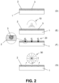
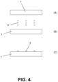
- the starting point is a substrate (A) on which a coating (2) is applied (B), the relief product (3) being applied (C) on the coating (2).
- the starting point is a substrate (A) on which a relief product (3) is applied (B, C) directly on the substrate (1).
- the coating (2) comes into contact (D) with the relief product (3), the coating (2) and the relief product (3) are cured (E), together or separately, obtaining the solidification of at least the relief product (3).
- Conventional curing means (10) can be used for curing, such as heating lamps or electromagnetic radiation emission, for example of UV, IR or electron emission light.
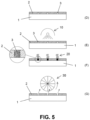
- the relief product (3) is sublimated (F).
- Conventional sublimation means (20) can be used for sublimation (F), such as by means of heating, in particular, by means of hot air or by means of heating lamps such as, for example, IR heating lamps. It is also envisaged that the sublimation (F) can be performed by reacting the relief product (3) with a sublimation activation product, for example, by applying said sublimation activation product on the relief product (3). The sublimation (F) can be simultaneously carried out, for example, with the solidification of the coating.
- means for removing material (30) can be used to remove (G) coating material in the areas affected by sublimation.
- These means (30) can be, for example, mechanical means such as brushing or vacuuming, or chemical means such as washing or rinsing of said areas.
- Figure 7 shows a process line according to the first preferred exemplary embodiment to obtain a relief (7) on a substrate (1) in the form of a panel.
- the substrate (1) advances through the different steps or stations being transported (60) by means of a conveyor belt (63).
- a liquid coating (2) is applied on the substrate (1), coating that is made of a UV-curable acrylic, by means of roller (70), using an applicator roller (71) and a dosing roller (72) in a manner known per se.
- the relief product (3) is applied on the coating (2) by means of inkjet digital printing (40) using a sublimation ink, which contains the relief product (3) dispersed in a UV-curable acrylic liquid, through injection heads (41) of the sublimation ink.
- the sublimation ink is applied on the coating (2) while this is still liquid, which facilitates the penetration of the sublimation ink, and therefore of the relief product (3) into the coating (2).
- the set of the coating (2) and sublimation ink that have been applied partially solidifies (10), being partially cured by means of a UV radiation lamp (11).
- the sublimation (20) of the product of the relief product (3) is carried out.
- heat is transferred to the relief product (3) by thermal conduction (22) by means of a heated roller (221) which rolls on the coating (2).
- This rolling is preferably synchronised with the advance of the substrate (1) along the process line, so that the heated roller (221) rolls substantially without sliding on the coating (2) for sublimating the relief product (3).
- sublimation material formed by coating affected by the sublimation of the relief product (3) and/or a residue of relief product (3) is projected on the outer surface of the heated roller (221).
- This sublimation material is cleaned (50) from the outer surface of the heated roller (221) by means of a scraping blade (51) for scraping the same.
- the gas from the sublimation of the relief product (3) is extracted (80) by means of an extraction hood (81).
- the coating finishes solidifying (10), being cured by means of a UV radiation lamp (12).
- a step for removing (30) excess material, such as coating affected by the sublimation of the relief product and/or a residue of relief product can be applied, for example, by means of brushing.
- Figure 8 shows a process line according to the second preferred exemplary embodiment to obtain a relief (7) on a substrate (1), wherein unlike the first exemplary embodiment, the substrate (1) is in the form of a continuous sheet.
- the sheet is fed continuously from a feed coil (5) to pass through the different stations or steps of the line until a collection coil (6), wherein the sheet is collected with the relief (7) produced on the substrate (1) for distribution or subsequent processing thereof.
- the sheet moves along the line by means of guide means, for example, guide rollers, in a manner known per se.
- the different steps or stations of this second exemplary embodiment are arranged or configured in a similar manner to the stations or steps of the first exemplary embodiment.
- a counter roller (71') of the applicator roller of the coating is incorporated, for positioning the substrate (1) by means of a counterpressure with said roller.
- a counter roller (221') of a heated roller is incorporated for positioning the substrate (1) by means of a counterpressure with said heated roller.
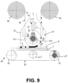
- Figure 9 shows a variant of the sublimation step or station (20), represented for the first exemplary embodiment but which can be similarly applicable to the second exemplary embodiment.
- the sublimation material formed by coating affected by the sublimation of the relief product (3) and/or a residue of relief product (3) instead of directly on the surface of the heated roller (221), is projected onto a sublimation material reception element, in the form of a reception strip (90).
- the reception strip (90) is fed from a feeding coil (93), being guided as it passes between the heated roller and the coating, until a collection coil (94), in which said sublimation material already deposited is collected for the external processing, recycling or removal thereof.
- Figure 9 also shows other constructive details of the heated roller (221) system.
- the heated roller (221) is able to move vertically by means of a vertical movement actuator (224) in an adjustable manner to move closer to the coating (2) with the relief product (3) applied therein, in cooperation with the counter roller (221'), for positioning the substrate (1) by exerting a counterpressure with said roller.
- the heated roller (221) is provided with a rotation actuator (223), to cause the heated roller (221) and the reception strip (90) to rotate on the coating (2) in a manner synchronised with the forward movement of the substrate (1), preferably substantially producing a rolling without sliding, at the same time that the advance of the reception strip (90) trapped between the heated roller (221) and the coating (2) occurs as the sublimation material is transferred to the reception strip (90).
- a conveyor belt (63) has been provided that moves guided by guide rollers (61, 62) and driven by means of a rotation actuator (64) which in the represented example acts to rotate one of the guide rollers (62).
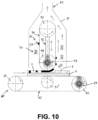
- Figure 10 shows another variant of the sublimation step or station (20), equally represented for the first exemplary embodiment but which can be similarly applied to the second exemplary embodiment.
- the reception strip (90) is continuously fed in a closed circuit being guided by means of guide rollers (91).
- the guide rollers (91) can move vertically to adjust the position of the guide roller (91) facing the coating (2) by means of a vertical movement actuator (95), enabling the substrate (1) to advance between this guide roller (91) and a counter roller (91').
- the reception strip (90) is moved by means of a rotation actuator (92) that causes, for example, said guide roller (91) facing the coating (2) to rotate.
- the sublimation material is transferred to the reception strip (90), however, in this variant, the reception strip (90) is refed once it has been cleaned (50) of sublimation material previously deposited on the same.
- Said cleaning (50) can be carried out, for example, as Figure 10 shows by means of a scraping blade (51) for scraping the reception strip (90), i.e., the contact surface of the reception strip (90) with the coating (2) when the sublimation material is transferred to the same.
- Figure 10 also shows sublimation means that are alternative or complementary to the heated roller (221) shown in the variants described above.
- the heating to produce the sublimation (20) can be carried out by thermal convection in the area of the guide roller (91) which faces the coating (2) by means of the strip of the reception strip (90).
- the strip (90) can be configured in a material, for example, metal, which facilitates thermal conduction in the coating (2) locally and/or be heated.
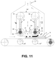
- Figure 11 shows another variant of the sublimation step or station (20), equally represented for the first exemplary embodiment but which can be similarly applied to the second exemplary embodiment.
- the sublimation is carried out by means of radiation heating (21).
- the heating can be carried out directly towards the coating (2), through a reception strip (90) of sublimation material transparent to the passage of the radiation, or indirectly by heating the reception strip (90).
- the heating (21) is carried out between two guide rollers (91) which are facing the coating (2) in two consecutive positions such that the reception strip (90) continuously remains in contact with the coating (2) between said two positions.
- a partial solidification (10) can be carried out by means of a UV radiation lamp (211) through a reception strip (90) transparent to said radiation. In this manner, a more efficient curing can be achieved, as the amount of air present between the strip (90) and the coating (2) in said area is reduced.
- Figure 12 shows another variant of the sublimation step or station (20), represented for the first exemplary embodiment but which can be similarly applied to the second exemplary embodiment.
- the heating of the coating to carry out the sublimation (20) is carried out by means of a thermal conduction element (22) in the form of a heated plate (222).
- the heated plate (222) can move vertically by means of vertical movement actuators (225) so that, to heat the coating (2) with the relief product (3) and produce the sublimation thereof, the plate (222) faces the coating (2) until making contact with the same, the substrate (1) remaining between the plate (222) and counter rollers (222').
- the cleaning (50) of the sublimation material transferred to the plate (222) is carried out by means of the scraping blade (51) that can move horizontally for sweeping said sublimation material, being deposited in a collection tray (52) of said removed material.
- Figure 13 shows another variant of the sublimation step or station (20), represented for the first exemplary embodiment but which can be similarly applied to the second exemplary embodiment.
- this variant embodiment unlike the variant shown in Figure 12 , there is a reception strip (90) of sublimation material that is arranged between the plate (222) and the coating (2) to receive the sublimation material from the coating (2).
- the reception strip (90) is cleaned (50) of said sublimation material by means of a scraping blade (51).
- the heating to produce the sublimation (20) can be carried out in a single step or station or in several steps or stations that are successive, consecutive with each other or alternated with other steps or stations of the method.
- a progressive heating of the coating (2) can be carried out before the sublimation starts, for example, by means of a plurality of conduction heating elements (22), such as heated rollers (221).
- the relief product (3) has been completely removed along with the coating (2) leaving a hollow (4) that has completely eliminated the thickness of said coating (2), thus reaching the bottom of said coating (2) and leaving the following layers exposed and visible.
- an image (2.2) is applied to the substrate (1) in correspondence with the relief obtained (7), with the decorative or functional layer (2.1) arranged on said image (2.2), achieving, among other characteristics such as for example, wear protection, different glosses that provide more realism to the relief obtained (7) on the substrate (1).
- said decorative or functional layer (2.1) can also be viewed through it.
- Caffeine or Camphor have been used as sublimatable products to obtain a practical embodiment sample with each one of them according to the invention.
- sublimatable product in the form of commercially available powders, these powders have a variety of particle sizes and can even have caked or agglomerated portions due to humidity.
- This powder was ground to obtain a sublimatable product powder with a particle size (D50) of 2000 ⁇ .
- said ground sublimatable product was dispersed in a dispersant consisting of an acrylic liquid partially inhibited to UV curing to form a colloidal solution with a sublimatable product concentration of approximately 5% by weight of the sublimation ink, obtaining a sublimation ink that can be used by means of inkjet printing.
- the sublimation ink was printed by inkjet, according to a digital template of a relief. Said digital printing was carried out on a liquid coating, of UV-curable acrylic varnish, previously applied on a wood substrate.
- the printing was carried out by means of printing heads marketed under the trademark Seiko 1536RC (heads with recirculation) as well as with printing heads marketed under the same trademark Seiko 508GS (without recirculation).
- the sample with the applied coating and the relief product was subjected to UV radiation by means of electric arc discharge lamps until partially curing the coating, until having a maximum curing degree of approximately 40% (with respect to the irradiated energy that would be required to completely cure the coating).
- the sample was heated by subjecting it to an IR radiation by means of IR lamps, until reaching a coating temperature of approximately 160 °C for the samples wherein the sublimatable product was Caffeine or a coating temperature of approximately 150 °C for the samples wherein the sublimatable product was Camphor.
- said sublimatable product was sublimated, producing a weakening in the coating in coating areas that determine the relief to be obtained (cavernous areas as a result of the evacuation of gas from the sublimation).
- the sample was subjected to a final curing for the total solidification thereof.
Landscapes
- Engineering & Computer Science (AREA)
- Architecture (AREA)
- Life Sciences & Earth Sciences (AREA)
- Wood Science & Technology (AREA)
- Civil Engineering (AREA)
- Structural Engineering (AREA)
- Application Of Or Painting With Fluid Materials (AREA)
- Printing Methods (AREA)
- Ink Jet (AREA)
- Shaping Of Tube Ends By Bending Or Straightening (AREA)
- Manufacturing Of Printed Wiring (AREA)
- Laminated Bodies (AREA)
- Manufacturing Optical Record Carriers (AREA)
Applications Claiming Priority (3)
| Application Number | Priority Date | Filing Date | Title |
|---|---|---|---|
| EP20382877.7A EP3932684B1 (fr) | 2020-10-02 | 2020-10-02 | Procédé et système de production d'un relief sur un substrat |
| PCT/ES2021/070697 WO2022069777A1 (fr) | 2020-10-02 | 2021-09-27 | Procédé et système pour produire un relief sur un substrat |
| EP21798404.6A EP4223546B1 (fr) | 2020-10-02 | 2021-09-27 | Procédé et système de production d'un relief sur un substrat |
Related Parent Applications (2)
| Application Number | Title | Priority Date | Filing Date |
|---|---|---|---|
| EP21798404.6A Division EP4223546B1 (fr) | 2020-10-02 | 2021-09-27 | Procédé et système de production d'un relief sur un substrat |
| EP21798404.6A Division-Into EP4223546B1 (fr) | 2020-10-02 | 2021-09-27 | Procédé et système de production d'un relief sur un substrat |
Publications (2)
| Publication Number | Publication Date |
|---|---|
| EP4286172A2 true EP4286172A2 (fr) | 2023-12-06 |
| EP4286172A3 EP4286172A3 (fr) | 2024-05-15 |
Family
ID=73476077
Family Applications (3)
| Application Number | Title | Priority Date | Filing Date |
|---|---|---|---|
| EP20382877.7A Active EP3932684B1 (fr) | 2020-10-02 | 2020-10-02 | Procédé et système de production d'un relief sur un substrat |
| EP21798404.6A Active EP4223546B1 (fr) | 2020-10-02 | 2021-09-27 | Procédé et système de production d'un relief sur un substrat |
| EP23203072.6A Pending EP4286172A3 (fr) | 2020-10-02 | 2021-09-27 | Procédé et système pour produire un relief sur un substrat |
Family Applications Before (2)
| Application Number | Title | Priority Date | Filing Date |
|---|---|---|---|
| EP20382877.7A Active EP3932684B1 (fr) | 2020-10-02 | 2020-10-02 | Procédé et système de production d'un relief sur un substrat |
| EP21798404.6A Active EP4223546B1 (fr) | 2020-10-02 | 2021-09-27 | Procédé et système de production d'un relief sur un substrat |
Country Status (15)
| Country | Link |
|---|---|
| US (1) | US12611888B2 (fr) |
| EP (3) | EP3932684B1 (fr) |
| JP (1) | JP7814059B2 (fr) |
| KR (1) | KR20230074498A (fr) |
| CN (1) | CN116234706B (fr) |
| BR (1) | BR112023005788A2 (fr) |
| ES (1) | ES2976640T3 (fr) |
| FI (1) | FI3932684T3 (fr) |
| HR (1) | HRP20240587T1 (fr) |
| HU (1) | HUE066459T2 (fr) |
| LT (1) | LT3932684T (fr) |
| PL (1) | PL3932684T3 (fr) |
| PT (1) | PT3932684T (fr) |
| SI (1) | SI3932684T1 (fr) |
| WO (1) | WO2022069777A1 (fr) |
Families Citing this family (2)
| Publication number | Priority date | Publication date | Assignee | Title |
|---|---|---|---|---|
| PL4215382T3 (pl) | 2022-01-24 | 2026-03-30 | Unilin, Bv | Sposób wytwarzania panelu |
| DE102022103652A1 (de) | 2022-02-16 | 2023-08-17 | Van Der Vlis Design Gmbh | Dreidimensional strukturiertes Dekorelement |
Family Cites Families (21)
| Publication number | Priority date | Publication date | Assignee | Title |
|---|---|---|---|---|
| JPS57187274A (en) * | 1981-05-12 | 1982-11-17 | Oki Electric Ind Co Ltd | Heat-sensitive copperplate recorder |
| US6521324B1 (en) * | 1999-11-30 | 2003-02-18 | 3M Innovative Properties Company | Thermal transfer of microstructured layers |
| JP3628937B2 (ja) * | 2000-05-18 | 2005-03-16 | 日新製鋼株式会社 | 熱転写染色法及び転写印刷装置 |
| CN100351080C (zh) * | 2002-11-14 | 2007-11-28 | 松下冷机株式会社 | 带升华转印图案的金属装饰板、使用其的隔热板和冰箱用外壁及其制造方法 |
| KR100492395B1 (ko) * | 2002-12-09 | 2005-06-08 | (주) 네오스텍 | 목재표면상에 칼라문양이나 사진을 전사하는 방법 |
| GB2397275A (en) * | 2003-01-15 | 2004-07-21 | Mega Electronics Ltd | Method of printing on anodised aluminium using sublimation inks |
| JP4419407B2 (ja) * | 2003-03-13 | 2010-02-24 | コニカミノルタホールディングス株式会社 | 防眩性反射防止層の形成方法及び防眩性反射防止フィルムの製造方法 |
| GB0326576D0 (en) * | 2003-11-14 | 2003-12-17 | Printetch Ltd | Printing composition |
| FR2937181B1 (fr) * | 2008-10-10 | 2011-01-14 | Commissariat Energie Atomique | Structuration en surface de couches minces par ejection localisee de liquide immiscible. |
| PT3831615T (pt) * | 2008-12-19 | 2025-03-11 | Unilin Bv | Painel revestido que compreende material sintético passível de ser espumado ou espumado |
| EP2263884A1 (fr) * | 2009-06-17 | 2010-12-22 | Coldenhove Know How B.V. | Papier peint et procédé de fabrication de papiers peints |
| US8337007B2 (en) * | 2010-08-16 | 2012-12-25 | Xerox Corporation | Curable sublimation ink and sublimation transfer process using same |
| JP2013241565A (ja) * | 2012-02-01 | 2013-12-05 | Mimaki Engineering Co Ltd | インク及びその利用 |
| US9528011B2 (en) * | 2013-01-11 | 2016-12-27 | Ceraloc Innovation Ab | Digital binder and powder print |
| ES2684783T3 (es) * | 2013-06-26 | 2018-10-04 | Fábrica Nacional De Moneda Y Timbre - Real Casa De La Moneda | Procedimiento para proporcionar una característica de seguridad a un documento de seguridad, y documento de seguridad |
| US9789706B2 (en) * | 2015-04-10 | 2017-10-17 | Electronics For Imaging, Inc. | Removable ultraviolet curable dye sublimation inks |
| NO2750604T3 (fr) * | 2015-06-25 | 2018-03-03 | ||
| CN109311337B (zh) * | 2016-05-30 | 2021-03-16 | 佳能株式会社 | 打印物、图像记录方法和图像记录设备 |
| PL3415316T3 (pl) * | 2017-06-13 | 2020-10-05 | Hymmen GmbH Maschinen- und Anlagenbau | Sposób i urządzenie do wytwarzania strukturyzowanej powierzchni |
| JP6985051B2 (ja) * | 2017-07-26 | 2021-12-22 | 株式会社ミマキエンジニアリング | 印刷方法、印刷装置、及び印刷システム |
| JP2020027828A (ja) * | 2018-08-09 | 2020-02-20 | 株式会社村田製作所 | 電子部品の製造装置 |
-
2020
- 2020-10-02 HR HRP20240587TT patent/HRP20240587T1/hr unknown
- 2020-10-02 HU HUE20382877A patent/HUE066459T2/hu unknown
- 2020-10-02 FI FIEP20382877.7T patent/FI3932684T3/fi active
- 2020-10-02 EP EP20382877.7A patent/EP3932684B1/fr active Active
- 2020-10-02 ES ES20382877T patent/ES2976640T3/es active Active
- 2020-10-02 PL PL20382877.7T patent/PL3932684T3/pl unknown
- 2020-10-02 LT LTEP20382877.7T patent/LT3932684T/lt unknown
- 2020-10-02 PT PT203828777T patent/PT3932684T/pt unknown
- 2020-10-02 SI SI202030429T patent/SI3932684T1/sl unknown
-
2021
- 2021-09-27 KR KR1020237011376A patent/KR20230074498A/ko active Pending
- 2021-09-27 CN CN202180067362.0A patent/CN116234706B/zh active Active
- 2021-09-27 EP EP21798404.6A patent/EP4223546B1/fr active Active
- 2021-09-27 EP EP23203072.6A patent/EP4286172A3/fr active Pending
- 2021-09-27 WO PCT/ES2021/070697 patent/WO2022069777A1/fr not_active Ceased
- 2021-09-27 JP JP2023520278A patent/JP7814059B2/ja active Active
- 2021-09-27 US US18/245,777 patent/US12611888B2/en active Active
- 2021-09-27 BR BR112023005788A patent/BR112023005788A2/pt unknown
Also Published As
| Publication number | Publication date |
|---|---|
| US20230331031A1 (en) | 2023-10-19 |
| SI3932684T1 (sl) | 2024-06-28 |
| US12611888B2 (en) | 2026-04-28 |
| PT3932684T (pt) | 2024-05-10 |
| EP4286172A3 (fr) | 2024-05-15 |
| EP4223546B1 (fr) | 2026-04-01 |
| LT3932684T (lt) | 2024-05-27 |
| HRP20240587T1 (hr) | 2024-07-19 |
| WO2022069777A1 (fr) | 2022-04-07 |
| EP4223546A1 (fr) | 2023-08-09 |
| EP3932684B1 (fr) | 2024-02-21 |
| JP7814059B2 (ja) | 2026-02-16 |
| ES2976640T3 (es) | 2024-08-06 |
| EP3932684A1 (fr) | 2022-01-05 |
| JP2023543626A (ja) | 2023-10-17 |
| BR112023005788A2 (pt) | 2023-04-25 |
| FI3932684T3 (fi) | 2024-05-15 |
| PL3932684T3 (pl) | 2024-07-15 |
| KR20230074498A (ko) | 2023-05-30 |
| CN116234706B (zh) | 2024-10-18 |
| HUE066459T2 (hu) | 2024-08-28 |
| CN116234706A (zh) | 2023-06-06 |
Similar Documents
| Publication | Publication Date | Title |
|---|---|---|
| CN112399922B (zh) | 在表面上形成结构的方法 | |
| EP2925529B1 (fr) | Procédé de production d'un panneau de bâtiment par impression numérique | |
| EP4223546B1 (fr) | Procédé et système de production d'un relief sur un substrat | |
| EP2218520B1 (fr) | Procédé et dispositif de fabrication d'une surface structurée | |
| US10369837B2 (en) | Method for forming a decorative design on an element of a wood-based material | |
| EP3825137B1 (fr) | Impression numérique à poudre et liant | |
| EP3109056B1 (fr) | Procede et dispositif de fabrication d'une structure sur une surface | |
| US9409382B2 (en) | Method of producing a building panel | |
| JP7638524B2 (ja) | 装飾デザインを備えた基材を製造するためのシステム | |
| CN105026172A (zh) | 数码热粘结剂和粉末印刷 | |
| KR102180851B1 (ko) | 디지털 프린팅용 건조 잉크 | |
| CN113874128A (zh) | 用于制造设有抗指纹覆层的消除光泽的载体材料的方法 | |
| BR112015016197B1 (pt) | Método de formação de uma impressão digital sobre uma superfície | |
| EP2556125A2 (fr) | Panneau de plancher doté d'une couche de liège imprimée | |
| JP7526508B2 (ja) | 浮き彫りを作製する方法及び機械、並びにその浮き彫りを備えたパネル | |
| DE102009044091A1 (de) | Verfahren zur Herstllung eines digitalbedruckten Werkstückes | |
| JP6704966B2 (ja) | デジタル結合剤及び粉体印刷 | |
| EP4265434B1 (fr) | Procédé et machine pour la décoration numérique d'un substrat |
Legal Events
| Date | Code | Title | Description |
|---|---|---|---|
| PUAI | Public reference made under article 153(3) epc to a published international application that has entered the european phase |
Free format text: ORIGINAL CODE: 0009012 |
|
| STAA | Information on the status of an ep patent application or granted ep patent |
Free format text: STATUS: THE APPLICATION HAS BEEN PUBLISHED |
|
| AC | Divisional application: reference to earlier application |
Ref document number: 4223546 Country of ref document: EP Kind code of ref document: P |
|
| AK | Designated contracting states |
Kind code of ref document: A2 Designated state(s): AL AT BE BG CH CY CZ DE DK EE ES FI FR GB GR HR HU IE IS IT LI LT LU LV MC MK MT NL NO PL PT RO RS SE SI SK SM TR |
|
| REG | Reference to a national code |
Ref country code: DE Ref legal event code: R079 Free format text: PREVIOUS MAIN CLASS: B41M0005000000 Ipc: B41M0003000000 |
|
| PUAL | Search report despatched |
Free format text: ORIGINAL CODE: 0009013 |
|
| AK | Designated contracting states |
Kind code of ref document: A3 Designated state(s): AL AT BE BG CH CY CZ DE DK EE ES FI FR GB GR HR HU IE IS IT LI LT LU LV MC MK MT NL NO PL PT RO RS SE SI SK SM TR |
|
| RIC1 | Information provided on ipc code assigned before grant |
Ipc: B41M 5/00 20060101ALN20240405BHEP Ipc: E04F 15/10 20060101ALI20240405BHEP Ipc: E04F 15/20 20060101ALI20240405BHEP Ipc: B44C 5/04 20060101ALI20240405BHEP Ipc: B44C 3/02 20060101ALI20240405BHEP Ipc: B44C 1/22 20060101ALI20240405BHEP Ipc: B41M 3/00 20060101AFI20240405BHEP |
|
| STAA | Information on the status of an ep patent application or granted ep patent |
Free format text: STATUS: REQUEST FOR EXAMINATION WAS MADE |
|
| 17P | Request for examination filed |
Effective date: 20241114 |
|
| RBV | Designated contracting states (corrected) |
Designated state(s): AL AT BE BG CH CY CZ DE DK EE ES FI FR GB GR HR HU IE IS IT LI LT LU LV MC MK MT NL NO PL PT RO RS SE SI SK SM TR |