EP4286181A2 - Mesures d'angle et d'orientation pour véhicules à plusieurs sections entraînables - Google Patents
Mesures d'angle et d'orientation pour véhicules à plusieurs sections entraînables Download PDFInfo
- Publication number
- EP4286181A2 EP4286181A2 EP23204718.3A EP23204718A EP4286181A2 EP 4286181 A2 EP4286181 A2 EP 4286181A2 EP 23204718 A EP23204718 A EP 23204718A EP 4286181 A2 EP4286181 A2 EP 4286181A2
- Authority
- EP
- European Patent Office
- Prior art keywords
- housing
- vehicle
- rotary encoder
- connector
- measurement device
- Prior art date
- Legal status (The legal status is an assumption and is not a legal conclusion. Google has not performed a legal analysis and makes no representation as to the accuracy of the status listed.)
- Withdrawn
Links
Images




Classifications
-
- B—PERFORMING OPERATIONS; TRANSPORTING
- B60—VEHICLES IN GENERAL
- B60D—VEHICLE CONNECTIONS
- B60D1/00—Traction couplings; Hitches; Draw-gear; Towing devices
- B60D1/24—Traction couplings; Hitches; Draw-gear; Towing devices characterised by arrangements for particular functions
- B60D1/245—Traction couplings; Hitches; Draw-gear; Towing devices characterised by arrangements for particular functions for facilitating push back or parking of trailers
-
- B—PERFORMING OPERATIONS; TRANSPORTING
- B62—LAND VEHICLES FOR TRAVELLING OTHERWISE THAN ON RAILS
- B62D—MOTOR VEHICLES; TRAILERS
- B62D15/00—Steering not otherwise provided for
- B62D15/02—Steering position indicators ; Steering position determination; Steering aids
- B62D15/021—Determination of steering angle
- B62D15/023—Determination of steering angle by measuring on the king pin
-
- B—PERFORMING OPERATIONS; TRANSPORTING
- B60—VEHICLES IN GENERAL
- B60W—CONJOINT CONTROL OF VEHICLE SUB-UNITS OF DIFFERENT TYPE OR DIFFERENT FUNCTION; CONTROL SYSTEMS SPECIALLY ADAPTED FOR HYBRID VEHICLES; ROAD VEHICLE DRIVE CONTROL SYSTEMS FOR PURPOSES NOT RELATED TO THE CONTROL OF A PARTICULAR SUB-UNIT
- B60W60/00—Drive control systems specially adapted for autonomous road vehicles
-
- B—PERFORMING OPERATIONS; TRANSPORTING
- B60—VEHICLES IN GENERAL
- B60D—VEHICLE CONNECTIONS
- B60D1/00—Traction couplings; Hitches; Draw-gear; Towing devices
- B60D1/58—Auxiliary devices
- B60D1/62—Auxiliary devices involving supply lines, electric circuits or the like
-
- B—PERFORMING OPERATIONS; TRANSPORTING
- B62—LAND VEHICLES FOR TRAVELLING OTHERWISE THAN ON RAILS
- B62D—MOTOR VEHICLES; TRAILERS
- B62D13/00—Steering specially adapted for trailers
- B62D13/06—Steering specially adapted for trailers for backing a normally drawn trailer
-
- B—PERFORMING OPERATIONS; TRANSPORTING
- B62—LAND VEHICLES FOR TRAVELLING OTHERWISE THAN ON RAILS
- B62D—MOTOR VEHICLES; TRAILERS
- B62D53/00—Tractor-trailer combinations; Road trains
- B62D53/04—Tractor-trailer combinations; Road trains comprising a vehicle carrying an essential part of the other vehicle's load by having supporting means for the front or rear part of the other vehicle
- B62D53/08—Fifth wheel traction couplings
-
- B—PERFORMING OPERATIONS; TRANSPORTING
- B62—LAND VEHICLES FOR TRAVELLING OTHERWISE THAN ON RAILS
- B62D—MOTOR VEHICLES; TRAILERS
- B62D53/00—Tractor-trailer combinations; Road trains
- B62D53/04—Tractor-trailer combinations; Road trains comprising a vehicle carrying an essential part of the other vehicle's load by having supporting means for the front or rear part of the other vehicle
- B62D53/08—Fifth wheel traction couplings
- B62D53/0871—Fifth wheel traction couplings with stabilising means, e.g. to prevent jack-knifing, pitching, rolling, buck jumping
-
- B—PERFORMING OPERATIONS; TRANSPORTING
- B62—LAND VEHICLES FOR TRAVELLING OTHERWISE THAN ON RAILS
- B62D—MOTOR VEHICLES; TRAILERS
- B62D53/00—Tractor-trailer combinations; Road trains
- B62D53/04—Tractor-trailer combinations; Road trains comprising a vehicle carrying an essential part of the other vehicle's load by having supporting means for the front or rear part of the other vehicle
- B62D53/08—Fifth wheel traction couplings
- B62D53/0842—King pins
Definitions
- This document relates to systems, apparatus, and methods to measure angles and/or orientations on a vehicle with multiple drivable sections.
- Autonomous vehicle navigation is a technology that can allow a vehicle to sense the position and movement of vehicles around an autonomous vehicle and, based on the sensing, control the autonomous vehicle to safely navigate towards a destination.
- An autonomous vehicle may control the steering angle, a throttle amount to control the speed of the autonomous vehicle, gear changes, and/or a breaking amount to control the extent to which the brakes are engaged.
- An autonomous vehicle may operate in several modes. In some cases, an autonomous vehicle may allow a driver to operate the autonomous vehicle as a conventional vehicle by controlling the steering, throttle, clutch, gear shifter, and/or other devices. In other cases, a driver may engage the autonomous vehicle navigation technology to allow the vehicle to be driven by itself.
- This patent document describes systems, apparatus, and methods to measure angles and/or orientations (e.g., directions of rotations) of a rear drivable section of a vehicle relative to a front drivable section of the vehicle.
- a vehicle comprises a front drivable section that comprises a first connector and a rotary encoder assembly.
- the first connector is coupled to a chassis of the front drivable section, where the first connector is located towards a rear region of the front drivable section.
- the rotary encoder assembly comprises a base surface, a housing and a rotary encoder.
- the base surface of the rotary encoder assembly includes the base surface that is coupled to a surface located below the first connector.
- the housing of the rotary encoder assembly includes a first end that is at least partially open and a second end that is opposite to the first end, where the second end of the housing is connected to the base surface, and where the first end of the housing is coupled to a housing cap.
- the rotary encoder assembly includes the rotary encoder that is located in the housing in between the base surface and the housing cap, where the rotary encoder includes a rotatable shaft that protrudes from a first hole located in the housing cap, and where a top of the rotatable shaft located away from the rotary encoder is coupled to one or more magnets.
- the rotary encoder is coupled to the housing cap via a plurality of non-rigid compressible couplings that include a plurality of shoulder screws, and at least some portion of each of the plurality of shoulder screws are located in one of a plurality of springs having first ends that are located below the housing cap and second ends that are opposite to the first ends that are located above the rotary encoder.
- the housing cap includes a first set of holes that are along a first perimeter of a first imaginary circle away from an edge of the housing cap, where each hole in the first set of holes includes a low-friction grommet through which a shoulder screw is coupled to the rotary encoder via a spring, where each shoulder screw includes a screw head on one end, a threaded surface on another opposite end, and a smooth shaft between the screw head and the threaded surface, and where the screw head of each shoulder screw is located at or above the housing cap, the smooth shaft of each should shoulder screw is located in one spring, and the threaded surface of each shoulder screw is located in a body of the rotary encoder.
- the housing cap includes a second set of holes that are along a second perimeter of a second imaginary circle that is closer to the edge of the housing cap than the first perimeter of the first imaginary circle that includes the first set of holes, where the second set of holes include screws that couple the housing cap to a flange located at the first end of the housing.
- a center region of the first connector includes a third hole, and where a top region of the rotary encoder assembly accessible via the third hole in the first connector.
- the plurality of shoulder screws and the plurality of springs are structured to have the rotary encoder retract in a first position away from the housing cap in response to an absence of a metallic material at the third hole in the first connector.
- the plurality of shoulder screws and the plurality of springs are structured to have the rotary encoder extend in a second position towards the housing cap in response to a presence of a magnetic material at the third hole in the first connector.
- the first connector comprises a groove located towards a rear of the front drivable section, and where the center region of the first connector where the groove ends includes the third hole.
- the vehicle further comprises a rear drivable section located behind the front drivable section, where the rear drivable section comprises a second connector coupled to the first connector, and where the second connector is magnetically coupled to the one or more magnets located on the top of the rotatable shaft of the rotary encoder assembly via the third hole in the first connector.
- the rotatable shaft of the rotary encoder is structured to have a rotational movement that corresponds to a circular movement of the second connector of the rear drivable section, and where the circular movement of the second connector of the rear drivable section is translated to the rotational movement of the rotatable shaft via the one or more magnets.
- the first connector includes a fifth wheel and where the second connector includes a king pin.
- the vehicle includes a semi-trailer truck, where the front drivable section includes a tractor unit, and where the rear drivable section includes a trailer unit.
- the front drivable section includes a computer comprising one or more processors and a memory configured to store one or more programs, where the one or more programs upon execution configure the one or more processors to: receive, from the rotary encoder and while the vehicle is operated on a road, information that indicates an angle or a direction of rotation of the rear drivable section relative to the front drivable section; cause the vehicle to perform an autonomous driving operation based on the angle or the direction of rotation of the rear drivable section.
- the one or more processors are configured to cause the vehicle to perform the autonomous driving operation by being configured to: determine that the angle of the rear drivable section is outside a range of angles allowed for the rear drivable section when the vehicle is operated on the road at a speed greater than or equal to a threshold value; and send instruction to a motor in a steering system of the vehicle to cause the vehicle to steer to move the trailer unit within the range of angles allowed for the rear drivable section.
- the one or more processors are further configured to: display, on a monitor located in the vehicle, the front drivable section and the rear drivable section, where an orientation of the rear drivable section relative to the front drivable section is displayed based on the angle received from the rotary encoder.
- the rotary encoder is connected to a movable cable
- the base surface includes a second hole located within a region where the housing is connected to the base surface such that at least some portion of the movable cable enters the housing via the second hole
- a rotary encoder assembly comprises a base surface, a housing, and a rotary encoder.
- the base surface of the rotary encoder assembly includes a plurality of holes located at close to an edge of the base surface.
- the housing of the rotary encoder assembly includes a first end that is at least partially open and a second end that is opposite to the first end, where the second end of the housing is connected to the base surface, and where the first end of the housing is coupled to a housing cap.
- the rotary encoder assembly includes the rotary encoder that is located in the housing in between the base surface and the housing cap, where the rotary encoder includes a rotatable shaft that protrudes from a first hole located in the housing cap, and where a top of the rotatable shaft located away from the rotary encoder is coupled to one or more magnets.
- the top of the rotatable shaft is coupled to the one or more magnets via a shaft adapter that is coupled to the rotatable shaft.
- the base surface includes a second hole located within a region where the housing is connected to the base surface such that the rotary encoder is connectable to a movable cable via the second hole, and the second hole in the base station includes a low-friction grommet through which the movable cable is connectable to the rotary encoder.
- the rotary encoder is coupled to the housing cap via a plurality of non-rigid compressible couplings.
- the first hole located in the housing cap includes a low-friction grommet through which at least some of the rotatable shaft protrudes from the first hole in the housing cap.
- the above-described methods and the methods described in this patent document are embodied in a computer readable program stored on a non-transitory computer readable media.
- the computer readable program includes code that when executed by a processor, causes the processor to perform the methods described in this patent document.
- a device is disclosed that is configured or operable to perform the above-described methods and/or methods described in this patent document.
- a semi-trailer trucks can have multiple drivable sections where, for example, a tractor unit where a driver may sit moves differently than a trailer unit where goods may be located, where the trailer unit is connected to the tractor unit.
- passenger vehicles can be more easily maneuvered on roads at least because passenger vehicles tend to have a single rigid body.
- This patent document describes technology that can enable a vehicle with multiple drivable sections (e.g., a semi-trailer truck with tractor unit and trailer unit, a truck or a car with fifth wheel camper) to measure an angle and/or orientation (e.g., direction or rotation) of a rear drivable section (e.g., trailer unit or fifth wheel camper) relative to a front drivable section (e.g., a tractor unit, truck, or car) so that the vehicle can be autonomously driven by taking into account, for example, the angle and/or orientation of the rear drivable section relative to the front drivable section.
- a vehicle with multiple drivable sections e.g., a semi-trailer truck with tractor unit and trailer unit, a truck or a car with fifth wheel camper
- an angle and/or orientation e.g., direction or rotation
- a rear drivable section e.g., trailer unit or fifth wheel camper
- Section I this patent document describes the devices located on or in a vehicle that can use angle and/or orientation measurements for autonomous driving operations.
- Section II of this patent document technologies are described to enable measurement of the angle and/or orientation of a rear drivable section of a vehicle relative to a front drivable section of the vehicle.
- the example headings for the various sections below are used to facilitate the understanding of the disclosed subject matter and do not limit the scope of the claimed subject matter in any way. Accordingly, one or more features of one example section can be combined with one or more features of another example section.
- FIG. 1 shows a block diagram of an example vehicle ecosystem 100 in which operations related to autonomous driving can be implemented in an in-vehicle control computer 150.
- the vehicle ecosystem 100 includes several systems and components that can generate and/or deliver one or more sources of information/data and related services to the in-vehicle control computer 150 that may be located in a vehicle 105. Examples of vehicle 105 include a car, a truck, or a semi-trailer truck.
- the in-vehicle control computer 150 can be in data communication with a plurality of vehicle subsystems 140, all of which can be resident in a user's vehicle 105.
- a vehicle subsystem interface 160 e.g., a controller area network (CAN) device
- CAN controller area network
- the vehicle 105 may include various vehicle subsystems that support of the operation of vehicle 105.
- the vehicle subsystems may include a vehicle drive subsystem 142, a vehicle sensor subsystem 144, and/or a vehicle control subsystem 146.
- the vehicle drive subsystem 142 may include components operable to provide powered motion for the vehicle 105.
- the vehicle drive subsystem 142 may include an engine or motor, wheels/tires, a transmission, an electrical subsystem, and a power source.
- the vehicle sensor subsystem 144 may include a number of sensors configured to sense information about an environment or condition of the vehicle 105.
- the vehicle sensor subsystem 144 may include a rotary encoder assembly, an inertial measurement unit (IMU), a Global Positioning System (GPS) transceiver, a RADAR unit, a laser range finder/LIDAR unit, and/or one or more cameras or image capture devices.
- IMU inertial measurement unit
- GPS Global Positioning System
- RADAR unit a laser range finder/LIDAR unit
- the rotary encoder assembly is designed or configured to provide one or more measurements related to angle and/or orientation of a rear drivable section (e.g., tractor unit) relative to the front drivable section (e.g., trailer unit).
- the rotary encoder assembly may be an absolute encoder that can provide angle and/or orientation of the rear drivable section relative to the front drivable section.
- the vehicle sensor subsystem 144 may also include sensors configured to monitor internal systems of the vehicle 105 (e.g., an O 2 monitor, a fuel gauge, an engine oil temperature).
- the IMU may include any combination of sensors (e.g., accelerometers and gyroscopes) configured to sense position and orientation changes of the vehicle 105 based on inertial acceleration.
- the GPS transceiver may be any sensor configured to estimate a geographic location of the vehicle 105.
- the GPS transceiver may include a receiver/transmitter operable to provide information regarding the position of the vehicle 105 with respect to the Earth.
- the RADAR unit may represent a system that utilizes radio signals to sense objects within the local environment of the vehicle 105. In some embodiments, in addition to sensing the objects, the RADAR unit may additionally be configured to sense the speed and the heading of the objects proximate to the vehicle 105.
- the laser range finder or LIDAR unit may be any sensor configured to sense objects in the environment in which the vehicle 105 is located using lasers.
- the cameras may include one or more devices configured to capture a plurality of images of the environment of the vehicle 105.
- the cameras may be still image cameras or motion video cameras.
- the vehicle control system 146 may be configured to control operation of the vehicle 105 and its components. Accordingly, the vehicle control system 146 may include various elements such as a throttle, a brake unit, a navigation unit, and/or a steering system.
- the throttle may be configured to control, for instance, the operating speed of the engine and, in turn, control the speed of the vehicle 105.
- the brake unit can include any combination of mechanisms configured to decelerate the vehicle 105.
- the brake unit can use friction to slow the wheels in a standard manner.
- the navigation unit may be any system configured to determine a driving path or route for the vehicle 105.
- the navigation unit may additionally be configured to update the driving path dynamically while the vehicle 105 is in operation.
- the navigation unit may be configured to incorporate data from the GPS transceiver and one or more predetermined maps so as to determine the driving path for the vehicle 105.
- the steering system may represent any combination of mechanisms that may be operable to adjust the heading of vehicle 105 in an autonomous mode or in a driver-controlled mode.
- the in-vehicle control computer 150 may include at least one data processor 170 (which can include at least one microprocessor) that executes processing instructions stored in a non-transitory computer readable medium, such as the memory 175.
- the in-vehicle control computer 150 may also represent a plurality of computing devices that may serve to control individual components or subsystems of the vehicle 105 in a distributed fashion.
- the data storage device 175 may contain processing instructions (e.g., program logic) executable by the data processor 170 to perform various methods and/or functions of the vehicle 105, including those described in this patent document.
- the data processor 170 executes the operations associated with autonomous driving module 165 for using the information provided by the rotary encoder assembly (e.g., the angle and/or orientation of the rear drivable section relative to the front drivable section of a vehicle 105) for operating the various vehicle subsystems (e.g., the vehicle drive subsystem 142, the vehicle sensor subsystem 144, and the vehicle control subsystem 146) of the vehicle 105 to autonomously operate the vehicle 105.
- the data storage device 175 may contain additional instructions as well, including instructions to transmit data to, receive data from, interact with, or control one or more of the vehicle drive subsystem 142, the vehicle sensor subsystem 144, and the vehicle control subsystem 146.
- the in-vehicle control computer 150 can be configured to include a data processor 170 and a data storage device 175.
- the in-vehicle control computer 150 may control the function of the vehicle 105 based on inputs received from various vehicle subsystems (e.g., the vehicle drive subsystem 142, the vehicle sensor subsystem 144, and the vehicle control subsystem 146). For example, the in-vehicle control computer 150 may use data from the rotary encoder assembly in order to control the steering system to turn the vehicle 105 by taking into account the orientation and angle of the rear drivable section relative to the front drivable section. In an example embodiment, the in-vehicle control computer 150 can be operable to provide control over many aspects of the vehicle 105 and its subsystems.
- vehicle subsystems e.g., the vehicle drive subsystem 142, the vehicle sensor subsystem 144, and the vehicle control subsystem 146.
- the in-vehicle control computer 150 may use data from the rotary encoder assembly in order to control the steering system to turn the vehicle 105 by taking into account the orientation and angle of the rear drivable section relative to the front d
- FIG. 2 shows a rear view of a semi-trailer truck with a fifth wheel.
- the semi-trailer truck includes a tractor unit 202 that includes a fifth wheel 204 that is located towards a rear region 212 of the tractor unit 202.
- the fifth wheel 204 is movably coupled to the chassis 210 of the semi-trailer truck so that the fifth wheel 204 can be moved towards or away from a cab 206 of the tractor unit 202 for installation of different types of trailer units.
- the fifth wheel 204 may have a "A" shape cutout region or upside down "V" shape cutout region or a groove that is located on the fifth wheel 204 towards the rear of the tractor unit 202 or away from a cab 206 in the tractor unit 202 where a driver may sit.
- the groove extends inwards from an edge of the fifth wheel 204 that is farthest away from the cab 206.
- the groove ends at a center region 208 of the fifth wheel 204.
- the groove in the fifth wheel allows a trailer unit's king pin to slide inside and lock the trailer unit and the fifth wheel together in place so that the trailer unit is coupled to the tractor unit via the king pin and the fifth wheel.
- the fifth wheel may be covered with grease so that the trailer unit can slide along the top surface of the fifth wheel.
- In the center region 208 of the groove is a hole through which a rotary encoder assembly can engage with a king pin of a trailer unit as further explained below.
- a fifth wheel does not include a position sensing equipment so that there may be no sensing or measurement of the angle of the trailer unit at the fifth-wheel.
- FIGS. 3A and 3B respectively show an isometric view and a top view of the fifth wheel 302 with a rotary encoder assembly 304 that is located in or below a hole 306 in the fifth wheel 302.
- FIG. 3C shows a side cross-section view of a trailer unit 308 and a fifth wheel 302 along with a direction in which a trailer unit 308 is moving to engage the fifth wheel 302.
- the trailer unit 308 includes a king pin 310 that slides within the groove of the fifth wheel 302 as the trailer engages the fifth wheel 302 in a direction from right to left in FIG. 3C .
- a mounting surface 316 that may be connected to the fifth wheel 302 so that the mounting surface 316 and the fifth wheel 302 can move towards or away from the cab in the tractor unit for installation of different types of trailer units.
- a bottom portion of a rotary encoder assembly 304 may be coupled to the mounting surface 316 below the fifth wheel 302.
- the rotary encoder assembly 304 is coupled to the mounting surface 316 below the fifth wheel 302 at a location where at least some portion of the rotary encoder assembly 304 overlaps with and is below the hole 306 in the fifth wheel 302 as shown in FIGS. 3A and 3B .
- the rotary encoder assembly 304 is coupled to the mounting surface 316 below the fifth wheel 302 at a location where the rotary encoder assembly 304 is directly below a center region of the fifth wheel 302 so that at least a top region of the rotary encoder assembly 304 is accessible via the hole 306.
- rotary encoder assembly 304 can be installed on a single tractor unit rather than being installed on multiple trailer units. Furthermore, the rotary encoder assembly 304 can installed on the tractor unit without involving the driver.
- Another technical benefit of the rotary encoder assembly being located on or in the tractor unit is that the rotary encoder assembly 304 can be communicably coupled (e.g., via a cable 314 in FIGS. 3D-3F ) to the in-vehicle control computer (shown as 150 in FIG. 1 ) which can also located in the tractor unit to provide an angle and/or an orientation related information of the trailer unit.
- FIG. 3D shows a side cross-section view of a trailer unit 308 and a fifth wheel 302 where the trailer unit 308 that has engaged the fifth wheel 302.
- a top region of the rotary encoder assembly 304 includes one or more magnets so that when a metallic king pin 310 (e.g., steel king pin) of the trailer unit 308 is within a magnetic field of the one or more magnets located on top of the rotary encoder assembly 304, at least some portion of the rotary encoder assembly 304, such as the rotary encoder 312, extends towards and magnetically couples with (or magnetically attaches to) the king pin 310.
- FIG. 1 shows a side cross-section view of a trailer unit 308 and a fifth wheel 302 where the trailer unit 308 that has engaged the fifth wheel 302.
- a top region of the rotary encoder assembly 304 includes one or more magnets so that when a metallic king pin 310 (e.g., steel king pin) of the trailer unit 308 is within
- 3E is an enlarged view of a rotary encoder assembly 304 with a rotary encoder 312 that is in a retracted position when the king pin 310 is moving to engage the fifth wheel 302 and is not close to the rotary encoder assembly 304 or when the king pin 310 is absent from the hole 306 in the fifth wheel 302.
- the arrow pointing to the left shows the movement of the king pin 310 and the trailer unit 308.
- FIG. 3F is an enlarged view of a rotary encoder assembly 304 with a rotary encoder 312 that is in an extended position when the king pin 310 is close to the rotary encoder assembly 304 and has engaged the fifth wheel or when at least a portion of the king pin 310 is located above the hole 306 in the fifth wheel 302.
- the arrow pointing up shows the movement of the rotary encoder 312 and the cable 314 in the rotary encoder assembly 304 when the one or more magnets on top of the rotary encoder assembly 304 are magnetically coupled with the king pin 310 so that the rotary encoder 312 in the rotary encoder assembly 304 is an extended position.
- the king pin 310 disengages the fifth wheel and moves away from the rotary encoder assembly 304, the king pin slides off the one or more magnets on top of the rotary encoder assembly 304 which causes the rotary encoder 312 to move downward and in a retracted position.
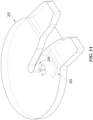
- FIGS. 4A and 4B respectively show an isometric view and a cross-section view of a rotary encoder assembly 400.
- the rotary encoder assembly 400 may include a housing 402 with top region (or one end) 402b and a bottom region 402a (or another end) that is opposite to the top region 402b.
- the bottom region 402a of the housing 402 is connected to a base surface 404.
- a top region 402b of housing 402 may have a circular opening with a flange 410 that extends outward from the perimeter of the top region of the housing 402.
- the housing 402 may have a cylindrical shape.
- the base surface 404 may have a square or rectangular shape with a plurality of holes that may be located close to (or at some distance away from) an edge of the base surface 404 (e.g., at the corners of the base surface 404).
- the base surface 404 may include a hole 422 located within a region 438 where the housing 402 is connected to the base surface 404.
- the hole 422 of the base surface 404 may be used to connect a cable 406 via the base surface 404 to the rotary encoder 408 that is enclosed within the housing 402.
- the cable 406 includes a set of wires to provide power to the rotary encoder 408 and to receive angle and/or orientation information measured by the rotary encoder 408 to send to the in-vehicle control computer (shown as 150 in FIG. 1 ).
- the cable 406 allows the rotary encoder 408 to interface with the in-vehicle control computer via the Society of Automotive Engineers standard SAE J1939 or via a Controller Area Network (CAN) bus. As shown in FIG.
- a low-friction grommet or a smooth grommet is located at the hole 422 of the base surface 404 in between the cable 406 and the hole 422 so that the rotary encoder 408 along with at least some portion of the cable 406 can move up and down as the compression springs 418 are respectively compressed and extended as further explained below.
- the base surface 404 may include four holes as shown in FIG. 4A , where each hole may be located at one of the corners of the base surface 404.
- the plurality of holes on the corners of the base surface 404 enable the base surface 404 to be coupled via screws to the mounting surface below the fifth wheel.
- the base surface 404 may have another shape, such as a circular, oval, or triangular shape where the plurality of holes used to couple the base surface 404 to the mounting surface below the fifth wheel may be located towards the perimeter of the base surface 404.
- the flange 410 of the housing 402 includes a plurality of holes that are located around the perimeter of the flange so that a housing cap 414 can be coupled to the housing 402 via screws.
- a housing cap 414 can be coupled to the housing 402 via screws.
- four screws 412a-412d that are located at or close to the outer perimeter of the housing cap 414 are used to secure the housing cap 414 to the flange 410 of the housing 402.
- the flange 410 may extend inward from the perimeter of the top region of the housing 402.
- the housing cap 414 can protect the rotary encoder 408 from the environment, such as from grease or debris that may fall from the trailer unit.
- the housing cap 414 may have flat circular shape which can correspond to the cylindrical shape of the housing 402 in some embodiments.
- the shape of housing cap 414 may extend up to an edge of the flange 410 or up to an outer wall of the housing 402.
- the housing cap 414 includes two sets of holes. A first set of holes in the housing cap 414 are located at a first perimeter that is close to the outer edge of the housing cap 414 so that a first set of a plurality of screws (e.g., four screws 412a-412d in FIG. 4A ) can be used to couple the housing cap 414 to the flange 410 of the housing 402.
- a second set of holes in the housing cap 414 are included at a second perimeter at some distance from the outer edge of the housing cap 414 so that a second set of a plurality of screws (e.g., four screws 416a-416d in FIG. 4A ) can be used to couple the rotary encoder 408 to the housing cap 414.
- the second perimeter of holes in the housing cap can be located within the first perimeter of holes in the housing cap.
- the second set of plurality of screws may be shoulder screws that have a screw head on one end, a threaded surface on another end, and a smooth shaft (e.g., a cylindrical shaft) between the screw head and the threaded surface.
- An example of a shoulder screw 416 is shown in FIG. 4C .
- the shoulder screws are inserted from the top of the housing cap 414 so that the screw head of each shoulder screw is located at or above the housing cap 414 and the threaded surface of each shoulder screw is screwed into the body of the rotary encoder 408.
- Each shoulder screw is inserted through a hole in the housing cap 414 thorough a low-friction grommet 420 or a smooth grommet 420 and then through a compression spring 418 to couple with the rotary encoder 408.
- the low-friction grommets or smooth grommets may be low-friction nylon shaft grommets located at the second set of holes in between the shoulder screws and the second set of holes.
- the ends of the compressions springs 418 are located in between the rotary encoder 408 and the housing cap 414 so that when the compression springs 418 are mostly extended, the rotary encoder 408 is in a retracted position away from the housing cap 414 within the housing 402 (as shown in FIG.
- the rotary encoder 408 when no trailer unit is engaged to the fifth wheel, the rotary encoder 408 is in a retracted position at least because the weight of the rotary encoder 408 and the compression springs 418 push the rotary encoder 408 downward.
- At least some portion of the smooth shaft of each shoulder screw is located inside the compression spring 418 so that the shoulder screws 416a-416d function as guide rods for compressions springs 418 which can create non-rigid compressible connections or non-rigid compressible couplings between the rotary encoder 408 and the housing 402 and/or between the rotary encoder 408 and the housing cap 414.
- FIG. 3F when the one or more magnets located on top of the rotary encoder assembly 400 is magnetically coupled to the king pin of the trailer unit, at least some portion of a top of the shoulder screws extend above the housing cap of the rotary encoder assembly 400 due to the one or more magnets pulling the rotary encoder 408 (shown as 312 in FIG. 3F ) along with the cable 406 (shown as 314 in FIG. 3F ) upward towards the king pin.
- the rotary encoder 408 may be a commercial off the shelf (COTS) absolute encoder that may provide an angle and/or orientation (e.g., direction of rotation) information to the in-vehicle control computer.
- the rotary encoder 408 may be a mechanical rotary encoder, an optical rotary encoder, or electrical rotary encoder.
- a top region of the rotary encoder 408 includes a rotatable shaft 424.
- the rotary encoder 408 measures an angle and/or orientation of the rotatable shaft 424 relative to the base surface 404 or the housing 402 of the rotary encoder assembly 400 so that the rotary encoder 408 provides electrical signals to the in-vehicle control computer indicating an angle and/or orientation of the rotatable shaft 424 relative to the base surface 404 or the housing 404 of the rotary encoder assembly 400.
- the rotatable shaft 424 After the rotatable shaft 424 extends with the rotary encoder 408 to couple to the king pin via the one or more magnets 430 and the shaft adapter 424 (as further explained below), the rotatable shaft 424 rotates together with the king pin as the trailer turns. Since the base surface 404 of the rotatable encoder assembly 400 is coupled to the mounting surface below the fifth wheel and since the rotary encoder 408 is coupled to the housing cap via the shoulder screws, when the rotary encoder 408 with the rotatable shaft 424 extends to magnetically couple the king pin, the rotatable shaft 424 of the rotary encoder 408 turns with the king pin while the body of the rotary encoder 408 mostly does not turn with the king pin.
- the circular movement of the king pin is translated to the rotatable movement or rotational movement of the rotatable shaft 424, which is used by the rotary encoder 408 to measure the angle and/or orientation of the trailer unit relative to the tractor unit.
- the rotatable shaft 424 protrudes or extends from a hole 426 in the center of the housing cap 414. As shown in FIG.
- a low-friction grommet or a smooth grommet is located at the hole 426 in the center of the housing cap 414 in between the rotatable shaft 424 and the hole 426 in the center of the housing cap 414 so that the rotatable shaft 424 (which is part of the rotary encoder 408) along with at least some portion of the cable 406 can move up and down as the compression springs 418 are respectively compressed and extended as explained above.
- a top region of the rotatable shaft 424 includes a shaft adapter 428 which can be coupled to the rotatable shaft by press fit or by a screw.
- the shaft adapter 428 may have a bottom region (e.g., a cylindrical shape region) that can couple to the rotatable shaft 424.
- the shaft adapter 428 may have a top region (e.g., a cylindrical shape region) that extends outward from the bottom region of the shaft adapter 428.
- the top region of the shaft adapter 428 has a larger width than the bottom region of the shaft adapter 428 so that the top region of the shaft adapter 428 can be coupled to one or more magnets 430. As shown in FIG.
- the top surface of the top region of the shaft adapter 428 may include a threaded hole 434 so that the one or more magnets 430 can be coupled to the top of the top region via the threaded hole 434 via a screw 436.
- One of the technical benefits of having one or more magnets 430 that can be couple to the top of the rotary encoder 408 is that the one or more magnets 430 can facilitate an easy or flexible height adjustment so that the top of the one or more magnets 430 can magnetically couple to the king pin of the trailer unit.
- the flexibility provided by the rotary encoder assembly design described in this document can minimize situations where different rotary encoder assemblies needs to be designed for different king pin design or for different mounting surfaces below the fifth wheel.
- the base surface 404, the housing 402, the housing cap 414, and/or the shaft adapter 428 can be made of machined aluminum or other non-magnetic metal so that at least these parts do not interfere with the magnetic coupling operation of the one or more magnets 430 with the king pin of the trailer unit.
- the angle and/or orientation information provided by the rotary encoder assembly may be used by the autonomous driving module 165 in the in-vehicle control computer 150 to control the vehicle 105.
- the angle and/or orientation information provided by the rotary encoder assembly along with videos from one or more cameras located on the vehicle 105 can enable the autonomous driving module 165 to display a position of the trailer unit on a screen in the vehicle 105 so that the driver may have an accurate understanding of the vehicle 105 with a trailer unit along with any objects surrounding the vehicle 105 when the vehicle is being parked.
- the autonomous driving module 165 can control the steering and/or braking of the vehicle 105 based at least on the angle and/or orientation information provided by the rotary encoder assembly. For example, when the vehicle 105 is autonomously parked in a dock or when the vehicle 105 is turning on a road, the autonomous driving module 165 can determine the angle and/or orientation of the trailer unit using the information provided by the rotary encoder assembly and the autonomous driving module 165 can determine position(s) of one or more objects (e.g., vehicles or pedestrians) using video from one or more cameras on the vehicle 105 to control the steering and/or braking of the vehicle 105 so that the movement of the trailer unit is controlled by the autonomous driving module 165.
- objects e.g., vehicles or pedestrians
- the autonomous driving module 165 can determine, using the video provided by the one or more cameras and the angle and/or orientation information from the rotary encoder assembly, that the trailer unit may hit another vehicle is located close to the trailer unit of the vehicle 105. In this example, the autonomous driving module 165 can determine a trajectory for the vehicle 105 to steer the vehicle 105 in a way to avoid having the trailer unit hit the vehicle or the autonomous driving module 165 may keep applying brakes until the another vehicle has driven away so that the autonomous driving module 165 can safely turn the vehicle 105.
- the autonomous driving module 165 may apply corrective steering to move the trailer unit to be within the range of angles from the position of the tractor unit.
- a gust of wind may have moved the trailer unit relative to the tractor unit so that if the trailer unit move to the left (assuming the vehicle 105 is driven in a north direction), then the autonomous driving module 165 can instruct the motors in the steering system to turn to the left to move the trailer unit back so that the angle formed by the trailer unit relative to the tractor unit is within the range of angles.
- the range of angles may be pre-determined or the range of angles may be a function of the speed of the vehicle (e.g., the range of angles is ⁇ 2 degrees of 180 degrees if the speed of the vehicle 105 is greater than or equal to a threshold value (e.g., 40 mph) and is ⁇ 1 degrees of 180 degrees if the speed of the vehicle is greater than or equal to another threshold value (e.g., 60 mph)).
- a threshold value e.g. 40 mph
- another threshold value e.g. 60 mph
- the autonomous driving module 165 can update an estimate of the center of gravity to establish a stable boundary around the vehicle 105 based on the angle and/or orientation information provided by the rotary encoder assembly. Knowing the center of gravity of the trailer unit as well as the tractor unit (also known as bobtail), the angle subtended by the trailer unit and the tractor unit can determine where an instantaneous center of gravity of the truck as a whole may be located. Unlike rigid vehicle such as cars and buses, vehicles with multiple drivable sections (e.g., a semi-trailer truck) have a moving center of gravity since it can be composed of at least two objects that are joined by the fifth wheel. In some embodiments, the autonomous driving module 165 may refer to a standard equation that provides an estimate of center of gravity based on an angle measured by the rotary encoder assembly.
- exemplary is used to mean “an example of' and, unless otherwise stated, does not imply an ideal or a preferred embodiment.
- the rotary encoder assembly may be installed on other types of multiple drivable sections (e.g., on or in a hitch on a truck or on a car with fifth wheel camper).
- a computer-readable medium may include removable and non-removable storage devices including, but not limited to, Read Only Memory (ROM), Random Access Memory (RAM), compact discs (CDs), digital versatile discs (DVDs), etc. Therefore, the computer-readable media can include a non-transitory storage media.
- program modules may include routines, programs, objects, components, data structures, etc. that perform particular tasks or implement particular abstract data types.
- Computer- or processor-executable instructions, associated data structures, and program modules represent examples of program code for executing steps of the methods disclosed herein. The particular sequence of such executable instructions or associated data structures represents examples of corresponding acts for implementing the functions described in such steps or processes.
- a hardware circuit implementation can include discrete analog and/or digital components that are, for example, integrated as part of a printed circuit board.
- the disclosed components or modules can be implemented as an Application Specific Integrated Circuit (ASIC) and/or as a Field Programmable Gate Array (FPGA) device.
- ASIC Application Specific Integrated Circuit
- FPGA Field Programmable Gate Array
- DSP digital signal processor
- the various components or sub-components within each module may be implemented in software, hardware or firmware.
- the connectivity between the modules and/or components within the modules may be provided using any one of the connectivity methods and media that is known in the art, including, but not limited to, communications over the Internet, wired, or wireless networks using the appropriate protocols.
Landscapes
- Engineering & Computer Science (AREA)
- Transportation (AREA)
- Mechanical Engineering (AREA)
- Chemical & Material Sciences (AREA)
- Combustion & Propulsion (AREA)
- Automation & Control Theory (AREA)
- Human Computer Interaction (AREA)
- Control Of Position, Course, Altitude, Or Attitude Of Moving Bodies (AREA)
- Transmission And Conversion Of Sensor Element Output (AREA)
- Vehicle Body Suspensions (AREA)
- Length Measuring Devices With Unspecified Measuring Means (AREA)
Applications Claiming Priority (2)
| Application Number | Priority Date | Filing Date | Title |
|---|---|---|---|
| US202063040662P | 2020-06-18 | 2020-06-18 | |
| EP21179854.1A EP3925865B1 (fr) | 2020-06-18 | 2021-06-16 | Mesures d'angle et d'orientation pour véhicules à plusieurs sections entraînables |
Related Parent Applications (2)
| Application Number | Title | Priority Date | Filing Date |
|---|---|---|---|
| EP21179854.1A Division EP3925865B1 (fr) | 2020-06-18 | 2021-06-16 | Mesures d'angle et d'orientation pour véhicules à plusieurs sections entraînables |
| EP21179854.1A Division-Into EP3925865B1 (fr) | 2020-06-18 | 2021-06-16 | Mesures d'angle et d'orientation pour véhicules à plusieurs sections entraînables |
Publications (2)
| Publication Number | Publication Date |
|---|---|
| EP4286181A2 true EP4286181A2 (fr) | 2023-12-06 |
| EP4286181A3 EP4286181A3 (fr) | 2024-05-15 |
Family
ID=76942708
Family Applications (2)
| Application Number | Title | Priority Date | Filing Date |
|---|---|---|---|
| EP23204718.3A Withdrawn EP4286181A3 (fr) | 2020-06-18 | 2021-06-16 | Mesures d'angle et d'orientation pour véhicules à plusieurs sections entraînables |
| EP21179854.1A Active EP3925865B1 (fr) | 2020-06-18 | 2021-06-16 | Mesures d'angle et d'orientation pour véhicules à plusieurs sections entraînables |
Family Applications After (1)
| Application Number | Title | Priority Date | Filing Date |
|---|---|---|---|
| EP21179854.1A Active EP3925865B1 (fr) | 2020-06-18 | 2021-06-16 | Mesures d'angle et d'orientation pour véhicules à plusieurs sections entraînables |
Country Status (5)
| Country | Link |
|---|---|
| US (3) | US11701931B2 (fr) |
| EP (2) | EP4286181A3 (fr) |
| JP (1) | JP7851694B2 (fr) |
| CN (1) | CN113815642A (fr) |
| AU (1) | AU2021203567A1 (fr) |
Families Citing this family (4)
| Publication number | Priority date | Publication date | Assignee | Title |
|---|---|---|---|---|
| AU2021203567A1 (en) | 2020-06-18 | 2022-01-20 | Tusimple, Inc. | Angle and orientation measurements for vehicles with multiple drivable sections |
| US12403852B2 (en) * | 2021-09-27 | 2025-09-02 | Grote Industries, Inc. | Light strip communication system |
| CN114584948B (zh) * | 2022-02-16 | 2024-04-23 | 上海师范大学 | 一种车载自组织网络十字路口数据传输系统及方法 |
| DE102022111393A1 (de) * | 2022-05-06 | 2023-11-09 | Jost-Werke Deutschland Gmbh | Sattelkupplungssystem, Zugfahrzeug und Sattelzug |
Family Cites Families (240)
| Publication number | Priority date | Publication date | Assignee | Title |
|---|---|---|---|---|
| DE2608513A1 (de) | 1976-03-02 | 1977-09-08 | Standard Elektrik Lorenz Ag | Anordnung zur weichensteuerung fuer ein verkehrssystem |
| JPS62111614U (fr) * | 1986-01-07 | 1987-07-16 | ||
| WO1991009375A1 (fr) | 1989-12-11 | 1991-06-27 | Caterpillar Inc. | Systeme, appareil et procede integres de calcul de position et de navigation pour vehicules |
| US5152544A (en) * | 1989-12-20 | 1992-10-06 | Eaton Corporation | Articulation angle sensor |
| JPH058425U (ja) * | 1991-07-12 | 1993-02-05 | アルプス電気株式会社 | 磁気式ロータリエンコーダ |
| US5877897A (en) | 1993-02-26 | 1999-03-02 | Donnelly Corporation | Automatic rearview mirror, vehicle lighting control and vehicle interior monitoring system using a photosensor array |
| US6822563B2 (en) | 1997-09-22 | 2004-11-23 | Donnelly Corporation | Vehicle imaging system with accessory control |
| US7103460B1 (en) | 1994-05-09 | 2006-09-05 | Automotive Technologies International, Inc. | System and method for vehicle diagnostics |
| US7783403B2 (en) | 1994-05-23 | 2010-08-24 | Automotive Technologies International, Inc. | System and method for preventing vehicular accidents |
| US7655894B2 (en) | 1996-03-25 | 2010-02-02 | Donnelly Corporation | Vehicular image sensing system |
| US6084870A (en) | 1996-07-22 | 2000-07-04 | Qualcomm Incorporated | Method and apparatus for the remote monitoring and configuration of electronic control systems |
| US6263088B1 (en) | 1997-06-19 | 2001-07-17 | Ncr Corporation | System and method for tracking movement of objects in a scene |
| JP3183501B2 (ja) | 1997-07-07 | 2001-07-09 | 本田技研工業株式会社 | 車両用走行制御装置 |
| US6594821B1 (en) | 2000-03-30 | 2003-07-15 | Transmeta Corporation | Translation consistency checking for modified target instructions by comparing to original copy |
| US8711217B2 (en) | 2000-10-24 | 2014-04-29 | Objectvideo, Inc. | Video surveillance system employing video primitives |
| US7363149B2 (en) | 2001-12-13 | 2008-04-22 | Robert Bosch Gmbh | Autonomous in-vehicle navigation system and diagnostic system |
| US7167519B2 (en) | 2001-12-20 | 2007-01-23 | Siemens Corporate Research, Inc. | Real-time video object generation for smart cameras |
| AU2003225228A1 (en) | 2002-05-03 | 2003-11-17 | Donnelly Corporation | Object detection system for vehicle |
| US9007197B2 (en) | 2002-05-20 | 2015-04-14 | Intelligent Technologies International, Inc. | Vehicular anticipatory sensor system |
| US6975923B2 (en) | 2002-10-01 | 2005-12-13 | Roke Manor Research Limited | Autonomous vehicle guidance on or near airports |
| US6777904B1 (en) | 2003-02-25 | 2004-08-17 | Ford Global Technologies, Llc | Method and system for controlling a motor |
| US8855405B2 (en) | 2003-04-30 | 2014-10-07 | Deere & Company | System and method for detecting and analyzing features in an agricultural field for vehicle guidance |
| US7130727B2 (en) | 2003-12-05 | 2006-10-31 | Full-View-Matic, Inc. | Vehicle safety system having methods and apparatus configurable for various vehicle geometries |
| WO2005098751A1 (fr) | 2004-04-08 | 2005-10-20 | Mobileye Technologies Limited | Detection de foule |
| US8082101B2 (en) | 2004-04-08 | 2011-12-20 | Mobileye Technologies Ltd. | Collision warning system |
| US20070230792A1 (en) | 2004-04-08 | 2007-10-04 | Mobileye Technologies Ltd. | Pedestrian Detection |
| US7526103B2 (en) | 2004-04-15 | 2009-04-28 | Donnelly Corporation | Imaging system for vehicle |
| DE102004040244A1 (de) * | 2004-08-13 | 2006-02-23 | Hübner Elektromaschinen GmbH | Drehgeber |
| US8078338B2 (en) | 2004-10-22 | 2011-12-13 | Irobot Corporation | System and method for behavior based control of an autonomous vehicle |
| DE112006000295T5 (de) | 2005-02-23 | 2008-04-17 | Matsushita Electric Works, Ltd., Kadoma | Autonomes Fahrzeug und Verfahren zur Erkennung von planaren Hindernissen |
| DE102005038570B4 (de) * | 2005-08-12 | 2008-09-18 | Sick Stegmann Gmbh | Drehgeber |
| KR100802511B1 (ko) | 2005-10-11 | 2008-02-13 | 주식회사 코리아 와이즈넛 | 토픽 기반의 검색 서비스 제공 시스템 및 그 방법 |
| EP1790541A2 (fr) | 2005-11-23 | 2007-05-30 | MobilEye Technologies, Ltd. | Procédés et systèmes pour détecter des obstructions dans le champ de vision d'une caméra |
| US8164628B2 (en) | 2006-01-04 | 2012-04-24 | Mobileye Technologies Ltd. | Estimating distance to an object using a sequence of images recorded by a monocular camera |
| US8265392B2 (en) | 2006-02-07 | 2012-09-11 | Qualcomm Incorporated | Inter-mode region-of-interest video object segmentation |
| US8150155B2 (en) | 2006-02-07 | 2012-04-03 | Qualcomm Incorporated | Multi-mode region-of-interest video object segmentation |
| US7689559B2 (en) | 2006-02-08 | 2010-03-30 | Telenor Asa | Document similarity scoring and ranking method, device and computer program product |
| US8050863B2 (en) | 2006-03-16 | 2011-11-01 | Gray & Company, Inc. | Navigation and control system for autonomous vehicles |
| US8417060B2 (en) | 2006-03-20 | 2013-04-09 | Arizona Board Of Regents For And On Behalf Of Arizona State University | Methods for multi-point descriptors for image registrations |
| US8108092B2 (en) | 2006-07-14 | 2012-01-31 | Irobot Corporation | Autonomous behaviors for a remote vehicle |
| US7786898B2 (en) | 2006-05-31 | 2010-08-31 | Mobileye Technologies Ltd. | Fusion of far infrared and visible images in enhanced obstacle detection in automotive applications |
| US8064643B2 (en) | 2006-12-06 | 2011-11-22 | Mobileye Technologies Limited | Detecting and recognizing traffic signs |
| JP5082472B2 (ja) * | 2007-01-31 | 2012-11-28 | 株式会社ニコン | ロータリエンコーダの位置決めユニットと、これを有するロータリエンコーダ |
| US20080249667A1 (en) | 2007-04-09 | 2008-10-09 | Microsoft Corporation | Learning and reasoning to enhance energy efficiency in transportation systems |
| US7839292B2 (en) | 2007-04-11 | 2010-11-23 | Nec Laboratories America, Inc. | Real-time driving danger level prediction |
| CA2683077A1 (fr) * | 2007-04-30 | 2008-11-06 | Silver Eagle Manufacturing Company | Appareil de sellette d'attelage stabilisateur antiroulis |
| US8229163B2 (en) | 2007-08-22 | 2012-07-24 | American Gnc Corporation | 4D GIS based virtual reality for moving target prediction |
| US8010252B2 (en) | 2007-10-05 | 2011-08-30 | Ford Global Technologies | Trailer oscillation detection and compensation method for a vehicle and trailer combination |
| US8041111B1 (en) | 2007-10-15 | 2011-10-18 | Adobe Systems Incorporated | Subjective and locatable color theme extraction for images |
| DE102007052759A1 (de) | 2007-11-06 | 2009-05-07 | Robert Bosch Gmbh | Fahrerassistenzsystem für Kraftfahrzeuggespanne |
| US9176006B2 (en) | 2008-01-15 | 2015-11-03 | Mobileye Vision Technologies Ltd. | Detection and classification of light sources using a diffraction grating |
| US9117133B2 (en) | 2008-06-18 | 2015-08-25 | Spectral Image, Inc. | Systems and methods for hyperspectral imaging |
| US20100049397A1 (en) | 2008-08-22 | 2010-02-25 | Garmin Ltd. | Fuel efficient routing |
| US8126642B2 (en) | 2008-10-24 | 2012-02-28 | Gray & Company, Inc. | Control and systems for autonomously driven vehicles |
| US8345956B2 (en) | 2008-11-03 | 2013-01-01 | Microsoft Corporation | Converting 2D video into stereo video |
| JP5222102B2 (ja) * | 2008-11-12 | 2013-06-26 | アバゴ・テクノロジーズ・イーシービーユー・アイピー(シンガポール)プライベート・リミテッド | ロータリエンコーダ |
| US9459515B2 (en) | 2008-12-05 | 2016-10-04 | Mobileye Vision Technologies Ltd. | Adjustable camera mount for a vehicle windshield |
| US8175376B2 (en) | 2009-03-09 | 2012-05-08 | Xerox Corporation | Framework for image thumbnailing based on visual similarity |
| US8582881B2 (en) | 2009-03-26 | 2013-11-12 | Tp Vision Holding B.V. | Method and apparatus for modifying an image by using a saliency map based on color frequency |
| US8271871B2 (en) | 2009-04-30 | 2012-09-18 | Xerox Corporation | Automated method for alignment of document objects |
| US8392117B2 (en) | 2009-05-22 | 2013-03-05 | Toyota Motor Engineering & Manufacturing North America, Inc. | Using topological structure for path planning in semi-structured environments |
| GB2470610A (en) * | 2009-05-30 | 2010-12-01 | John Paul Standen | Angle sensor monitoring system for trailer towing vehicles |
| EP2275604B1 (fr) | 2009-06-17 | 2012-04-18 | BAUER Maschinen GmbH | Engine avec une jumelle |
| US9002632B1 (en) | 2009-07-19 | 2015-04-07 | Aaron T. Emigh | Fuel cost optimized routing |
| EP2306156B1 (fr) * | 2009-10-01 | 2012-12-12 | SICK STEGMANN GmbH | Codeur |
| DE102009046124A1 (de) | 2009-10-28 | 2011-05-05 | Ifm Electronic Gmbh | Verfahren und Vorrichtung zur Kalibrierung eines 3D-TOF-Kamerasystems |
| TWI393074B (zh) | 2009-12-10 | 2013-04-11 | Ind Tech Res Inst | 移動物體偵測裝置與方法 |
| JP2011176748A (ja) | 2010-02-25 | 2011-09-08 | Sony Corp | 画像処理装置および方法、並びにプログラム |
| US8726305B2 (en) | 2010-04-02 | 2014-05-13 | Yahoo! Inc. | Methods and systems for application rendering and management on internet television enabled displays |
| KR101145112B1 (ko) | 2010-05-11 | 2012-05-14 | 국방과학연구소 | 자율이동차량의 조향제어장치, 이를 구비하는 자율이동차량 및 자율이동차량의 조향제어방법 |
| US9753128B2 (en) | 2010-07-23 | 2017-09-05 | Heptagon Micro Optics Pte. Ltd. | Multi-path compensation using multiple modulation frequencies in time of flight sensor |
| US8412406B2 (en) | 2010-08-13 | 2013-04-02 | Deere & Company | Method and system for performing diagnostics or software maintenance for a vehicle |
| US9280711B2 (en) | 2010-09-21 | 2016-03-08 | Mobileye Vision Technologies Ltd. | Barrier and guardrail detection using a single camera |
| US9118816B2 (en) | 2011-12-06 | 2015-08-25 | Mobileye Vision Technologies Ltd. | Road vertical contour detection |
| US8509982B2 (en) | 2010-10-05 | 2013-08-13 | Google Inc. | Zone driving |
| EP3588939B1 (fr) | 2010-10-31 | 2023-10-18 | Mobileye Vision Technologies Ltd. | Regroupement de systèmes d'assistance au conducteur en vision nocturne et autres utilisant un éclairage à infrarouge proche et un obturateur déroulant |
| CN103210651B (zh) | 2010-11-15 | 2016-11-09 | 华为技术有限公司 | 用于视频概要的方法和系统 |
| US9251708B2 (en) | 2010-12-07 | 2016-02-02 | Mobileye Vision Technologies Ltd. | Forward collision warning trap and pedestrian advanced warning system |
| US9823339B2 (en) | 2010-12-21 | 2017-11-21 | Microsoft Technology Licensing, Llc | Plural anode time-of-flight sensor |
| AU2012206427A1 (en) | 2011-01-14 | 2013-08-01 | Bae Systems Plc | Data transfer system and method thereof |
| US9323250B2 (en) | 2011-01-28 | 2016-04-26 | Intouch Technologies, Inc. | Time-dependent navigation of telepresence robots |
| JP6110316B2 (ja) | 2011-02-21 | 2017-04-05 | ストラテック システムズ リミテッドStratech Systems Limited | 監視システムおよび飛行場内の異物、破片、または損害を検出する方法 |
| US8401292B2 (en) | 2011-04-26 | 2013-03-19 | Eastman Kodak Company | Identifying high saliency regions in digital images |
| US9233659B2 (en) | 2011-04-27 | 2016-01-12 | Mobileye Vision Technologies Ltd. | Pedestrian collision warning system |
| KR101777875B1 (ko) | 2011-04-28 | 2017-09-13 | 엘지디스플레이 주식회사 | 입체 영상 표시장치와 그 입체 영상 조절 방법 |
| JP2012255709A (ja) | 2011-06-08 | 2012-12-27 | Komatsu Ltd | ロータリエンコーダ |
| US20120314070A1 (en) | 2011-06-09 | 2012-12-13 | GM Global Technology Operations LLC | Lane sensing enhancement through object vehicle information for lane centering/keeping |
| US9183447B1 (en) | 2011-06-09 | 2015-11-10 | Mobileye Vision Technologies Ltd. | Object detection using candidate object alignment |
| GB2492848A (en) | 2011-07-15 | 2013-01-16 | Softkinetic Sensors Nv | Optical distance measurement |
| US9490064B2 (en) | 2011-07-28 | 2016-11-08 | Honda Motor Co., Ltd. | Wireless power transmission method |
| US8744123B2 (en) | 2011-08-29 | 2014-06-03 | International Business Machines Corporation | Modeling of temporarily static objects in surveillance video data |
| US8891820B2 (en) | 2011-09-29 | 2014-11-18 | The Boeing Company | Multi-modal sensor fusion |
| DE102011083749B4 (de) | 2011-09-29 | 2015-06-11 | Aktiebolaget Skf | Rotorblatt einer Windkraftanlage mit einer Vorrichtung zum Erfassen eines Abstandswertes und Verfahren zum Erfassen eines Abstandswertes |
| US8917170B2 (en) * | 2011-10-04 | 2014-12-23 | Santo A. Padula | Apparatus for measuring articulation angle between a tractor and trailer in an articulated vehicle |
| US20140143839A1 (en) | 2011-11-16 | 2014-05-22 | Flextronics Ap, Llc. | On board vehicle remote control module |
| WO2013084225A1 (fr) | 2011-12-05 | 2013-06-13 | Brightway Vision Ltd. | Système intelligent de signalisation routière et procédé associé |
| US9297641B2 (en) | 2011-12-12 | 2016-03-29 | Mobileye Vision Technologies Ltd. | Detection of obstacles at night by analysis of shadows |
| FR2984254B1 (fr) | 2011-12-16 | 2016-07-01 | Renault Sa | Controle de vehicules autonomes |
| US8810666B2 (en) | 2012-01-16 | 2014-08-19 | Google Inc. | Methods and systems for processing a video for stabilization using dynamic crop |
| JP5605381B2 (ja) | 2012-02-13 | 2014-10-15 | 株式会社デンソー | クルーズ制御装置 |
| US9042648B2 (en) | 2012-02-23 | 2015-05-26 | Microsoft Technology Licensing, Llc | Salient object segmentation |
| US8457827B1 (en) | 2012-03-15 | 2013-06-04 | Google Inc. | Modifying behavior of autonomous vehicle based on predicted behavior of other vehicles |
| US9476970B1 (en) | 2012-03-19 | 2016-10-25 | Google Inc. | Camera based localization |
| US8737690B2 (en) | 2012-04-06 | 2014-05-27 | Xerox Corporation | Video-based method for parking angle violation detection |
| US8718861B1 (en) | 2012-04-11 | 2014-05-06 | Google Inc. | Determining when to drive autonomously |
| US9549158B2 (en) | 2012-04-18 | 2017-01-17 | Brightway Vision Ltd. | Controllable single pixel sensors |
| US9723233B2 (en) | 2012-04-18 | 2017-08-01 | Brightway Vision Ltd. | Controllable gated sensor |
| KR102039894B1 (ko) | 2012-04-18 | 2019-11-04 | 브라이트웨이 비젼 엘티디. | 리드아웃 별 다중 게이트 픽셀 |
| KR102144521B1 (ko) | 2012-05-29 | 2020-08-14 | 브라이트웨이 비젼 엘티디. | 적응 피사계심도를 이용한 게이트된 영상 획득 방법 및 영상 시스템 |
| US9134402B2 (en) | 2012-08-13 | 2015-09-15 | Digital Signal Corporation | System and method for calibrating video and lidar subsystems |
| WO2014030164A1 (fr) | 2012-08-21 | 2014-02-27 | Brightway Vision Ltd. | Éclairage simultané de feux de signalisation à des distances différentes |
| US9025880B2 (en) | 2012-08-29 | 2015-05-05 | Disney Enterprises, Inc. | Visual saliency estimation for images and video |
| US9165190B2 (en) | 2012-09-12 | 2015-10-20 | Avigilon Fortress Corporation | 3D human pose and shape modeling |
| US9120485B1 (en) | 2012-09-14 | 2015-09-01 | Google Inc. | Methods and systems for smooth trajectory generation for a self-driving vehicle |
| US9111444B2 (en) | 2012-10-31 | 2015-08-18 | Raytheon Company | Video and lidar target detection and tracking system and method for segmenting moving targets |
| WO2014088997A1 (fr) | 2012-12-03 | 2014-06-12 | Abb Technology Ag | Téléopération de machines ayant au moins un mécanisme actionné et une première unité de commande de machine comprenant un code de programme comportant des instructions pour transférer une commande de la machine de ladite unité de commande à une station de commande à distance |
| US9625569B2 (en) | 2012-12-17 | 2017-04-18 | pmdtechnologies ag | Time-of-flight camera with motion detection |
| US9602807B2 (en) | 2012-12-19 | 2017-03-21 | Microsoft Technology Licensing, Llc | Single frequency time of flight de-aliasing |
| US9081385B1 (en) | 2012-12-21 | 2015-07-14 | Google Inc. | Lane boundary detection using images |
| US9092430B2 (en) | 2013-01-02 | 2015-07-28 | International Business Machines Corporation | Assigning shared catalogs to cache structures in a cluster computing system |
| US8788134B1 (en) | 2013-01-04 | 2014-07-22 | GM Global Technology Operations LLC | Autonomous driving merge management system |
| JP6285958B2 (ja) | 2013-01-15 | 2018-02-28 | モービルアイ ビジョン テクノロジーズ リミテッド | ローリングシャッターを伴うステレオ支援 |
| US9277132B2 (en) | 2013-02-21 | 2016-03-01 | Mobileye Vision Technologies Ltd. | Image distortion correction of a camera with a rolling shutter |
| US9111355B1 (en) | 2013-03-13 | 2015-08-18 | Hrl Laboratories, Llc | Selective color processing for vision systems that enables optimal detection and recognition |
| US9147255B1 (en) | 2013-03-14 | 2015-09-29 | Hrl Laboratories, Llc | Rapid object detection by combining structural information from image segmentation with bio-inspired attentional mechanisms |
| US9652860B1 (en) | 2013-03-15 | 2017-05-16 | Puretech Systems, Inc. | System and method for autonomous PTZ tracking of aerial targets |
| US9342074B2 (en) | 2013-04-05 | 2016-05-17 | Google Inc. | Systems and methods for transitioning control of an autonomous vehicle to a driver |
| CN103198128A (zh) | 2013-04-11 | 2013-07-10 | 苏州阔地网络科技有限公司 | 一种云教育平台的数据搜索方法及系统 |
| GB2513392B (en) | 2013-04-26 | 2016-06-08 | Jaguar Land Rover Ltd | System for a towing vehicle |
| AU2013205548A1 (en) | 2013-04-30 | 2014-11-13 | Canon Kabushiki Kaisha | Method, system and apparatus for tracking objects of a scene |
| US9438878B2 (en) | 2013-05-01 | 2016-09-06 | Legend3D, Inc. | Method of converting 2D video to 3D video using 3D object models |
| US9025825B2 (en) | 2013-05-10 | 2015-05-05 | Palo Alto Research Center Incorporated | System and method for visual motion based object segmentation and tracking |
| US9729860B2 (en) | 2013-05-24 | 2017-08-08 | Microsoft Technology Licensing, Llc | Indirect reflection suppression in depth imaging |
| EP3008708B1 (fr) | 2013-06-13 | 2019-12-18 | Mobileye Vision Technologies Ltd. | Navigation améliorée par vision |
| EP3015836A4 (fr) * | 2013-06-25 | 2017-06-21 | NSK Ltd. | Dispositif de transmission de rotation |
| IL227265A0 (en) | 2013-06-30 | 2013-12-31 | Brightway Vision Ltd | Smart flash for the camera |
| KR102111784B1 (ko) | 2013-07-17 | 2020-05-15 | 현대모비스 주식회사 | 차량 위치 인식 장치 및 방법 |
| US9315192B1 (en) | 2013-09-30 | 2016-04-19 | Google Inc. | Methods and systems for pedestrian avoidance using LIDAR |
| US9122954B2 (en) | 2013-10-01 | 2015-09-01 | Mobileye Vision Technologies Ltd. | Performing a histogram using an array of addressable registers |
| US9738280B2 (en) | 2013-10-03 | 2017-08-22 | Robert Bosch Gmbh | Adaptive cruise control with on-ramp detection |
| US9330334B2 (en) | 2013-10-24 | 2016-05-03 | Adobe Systems Incorporated | Iterative saliency map estimation |
| US9299004B2 (en) | 2013-10-24 | 2016-03-29 | Adobe Systems Incorporated | Image foreground detection |
| US9656673B2 (en) | 2013-12-04 | 2017-05-23 | Mobileye Vision Technologies Ltd. | Systems and methods for navigating a vehicle to a default lane |
| EP2887311B1 (fr) | 2013-12-20 | 2016-09-14 | Thomson Licensing | Procédé et appareil permettant d'effectuer une estimation de profondeur |
| CA2935617C (fr) | 2013-12-30 | 2023-09-12 | Craig Arnold Tieman | Systeme de vehicule connecte a interface d'infodivertissement pour dispositifs mobiles |
| WO2015116950A1 (fr) | 2014-01-30 | 2015-08-06 | Anna Clarke | Systèmes et procédés de reconnaissance de fin de voie |
| CN109884618B (zh) | 2014-02-20 | 2023-05-26 | 御眼视觉技术有限公司 | 车辆的导航系统、包括导航系统的车辆和导航车辆的方法 |
| CN103793925B (zh) | 2014-02-24 | 2016-05-18 | 北京工业大学 | 融合时空特征的视频图像视觉显著程度检测方法 |
| US9981389B2 (en) | 2014-03-03 | 2018-05-29 | California Institute Of Technology | Robotics platforms incorporating manipulators having common joint designs |
| US9476730B2 (en) | 2014-03-18 | 2016-10-25 | Sri International | Real-time system for multi-modal 3D geospatial mapping, object recognition, scene annotation and analytics |
| DE102014205170A1 (de) | 2014-03-20 | 2015-11-26 | Bayerische Motoren Werke Aktiengesellschaft | Verfahren und Vorrichtung zum Ermitteln einer Trajektorie für ein Fahrzeug |
| US9739609B1 (en) | 2014-03-25 | 2017-08-22 | Amazon Technologies, Inc. | Time-of-flight sensor with configurable phase delay |
| US9471889B2 (en) | 2014-04-24 | 2016-10-18 | Xerox Corporation | Video tracking based method for automatic sequencing of vehicles in drive-thru applications |
| CN105100134A (zh) | 2014-04-28 | 2015-11-25 | 思科技术公司 | 屏幕共享缓存管理 |
| EP4187523A1 (fr) | 2014-05-14 | 2023-05-31 | Mobileye Vision Technologies Ltd. | Systèmes et procédés de détection de bordure de trottoir et d'évaluation des risques pour les piétons |
| US9720418B2 (en) | 2014-05-27 | 2017-08-01 | Here Global B.V. | Autonomous vehicle monitoring and control |
| EP3152704A2 (fr) | 2014-06-03 | 2017-04-12 | Mobileye Vision Technologies Ltd. | Systèmes et procédés pour détecter un objet |
| US9457807B2 (en) | 2014-06-05 | 2016-10-04 | GM Global Technology Operations LLC | Unified motion planning algorithm for autonomous driving vehicle in obstacle avoidance maneuver |
| IL233356A (en) | 2014-06-24 | 2015-10-29 | Brightway Vision Ltd | Sensor-based imaging system with minimum wait time between sensor exposures |
| US9628565B2 (en) | 2014-07-23 | 2017-04-18 | Here Global B.V. | Highly assisted driving platform |
| US9766625B2 (en) | 2014-07-25 | 2017-09-19 | Here Global B.V. | Personalized driving of autonomously driven vehicles |
| US20160026787A1 (en) | 2014-07-25 | 2016-01-28 | GM Global Technology Operations LLC | Authenticating messages sent over a vehicle bus that include message authentication codes |
| US9554030B2 (en) | 2014-09-29 | 2017-01-24 | Yahoo! Inc. | Mobile device image acquisition using objects of interest recognition |
| US9248834B1 (en) | 2014-10-02 | 2016-02-02 | Google Inc. | Predicting trajectories of objects based on contextual information |
| US9746550B2 (en) | 2014-10-08 | 2017-08-29 | Ford Global Technologies, Llc | Detecting low-speed close-range vehicle cut-in |
| US9779276B2 (en) | 2014-10-10 | 2017-10-03 | Hand Held Products, Inc. | Depth sensor based auto-focus system for an indicia scanner |
| US9773155B2 (en) | 2014-10-14 | 2017-09-26 | Microsoft Technology Licensing, Llc | Depth from time of flight camera |
| US9959903B2 (en) | 2014-10-23 | 2018-05-01 | Qnap Systems, Inc. | Video playback method |
| US9547985B2 (en) | 2014-11-05 | 2017-01-17 | Here Global B.V. | Method and apparatus for providing access to autonomous vehicles based on user context |
| KR101664582B1 (ko) | 2014-11-12 | 2016-10-10 | 현대자동차주식회사 | 자율주행차량의 주행경로 생성장치 및 방법 |
| KR102312273B1 (ko) | 2014-11-13 | 2021-10-12 | 삼성전자주식회사 | 거리영상 측정용 카메라 및 그 동작방법 |
| US9494935B2 (en) | 2014-11-13 | 2016-11-15 | Toyota Motor Engineering & Manufacturing North America, Inc. | Remote operation of autonomous vehicle in unexpected environment |
| WO2016090282A1 (fr) | 2014-12-05 | 2016-06-09 | Cowbyt Technologies Llc | Système de navigation autonome |
| US9347779B1 (en) | 2014-12-10 | 2016-05-24 | Here Global B.V. | Method and apparatus for determining a position of a vehicle based on driving behavior |
| US9805294B2 (en) | 2015-02-12 | 2017-10-31 | Mitsubishi Electric Research Laboratories, Inc. | Method for denoising time-of-flight range images |
| US10115024B2 (en) | 2015-02-26 | 2018-10-30 | Mobileye Vision Technologies Ltd. | Road vertical contour detection using a stabilized coordinate frame |
| US9804022B2 (en) | 2015-03-24 | 2017-10-31 | Ford Global Technologies, Llc | System and method for hitch angle detection |
| JP6421684B2 (ja) | 2015-04-17 | 2018-11-14 | 井関農機株式会社 | 乗用草刈機 |
| US9649999B1 (en) | 2015-04-28 | 2017-05-16 | Sprint Communications Company L.P. | Vehicle remote operations control |
| US10635761B2 (en) | 2015-04-29 | 2020-04-28 | Energid Technologies Corporation | System and method for evaluation of object autonomy |
| US9483839B1 (en) | 2015-05-06 | 2016-11-01 | The Boeing Company | Occlusion-robust visual object fingerprinting using fusion of multiple sub-region signatures |
| US10345809B2 (en) | 2015-05-13 | 2019-07-09 | Uber Technologies, Inc. | Providing remote assistance to an autonomous vehicle |
| US9613273B2 (en) | 2015-05-19 | 2017-04-04 | Toyota Motor Engineering & Manufacturing North America, Inc. | Apparatus and method for object tracking |
| US9690290B2 (en) | 2015-06-04 | 2017-06-27 | Toyota Motor Engineering & Manufacturing North America, Inc. | Situation-based transfer of vehicle sensor data during remote operation of autonomous vehicles |
| DE102015211926A1 (de) | 2015-06-26 | 2016-12-29 | Robert Bosch Gmbh | Verfahren und Vorrichtung zum Ermitteln bzw. Bewerten einer Soll-Trajektorie eines Kraftfahrzeugs |
| WO2017013875A1 (fr) | 2015-07-23 | 2017-01-26 | 日本電気株式会社 | Dispositif de commutation de route, système de commutation de route et procédé de commutation de route |
| US9989965B2 (en) | 2015-08-20 | 2018-06-05 | Motionloft, Inc. | Object detection and analysis via unmanned aerial vehicle |
| US10282591B2 (en) | 2015-08-24 | 2019-05-07 | Qualcomm Incorporated | Systems and methods for depth map sampling |
| US9587952B1 (en) | 2015-09-09 | 2017-03-07 | Allstate Insurance Company | Altering autonomous or semi-autonomous vehicle operation based on route traversal values |
| CN119645078A (zh) | 2015-09-15 | 2025-03-18 | 深圳市大疆创新科技有限公司 | 控制可移动物体跟踪目标的系统和方法 |
| DE102015012362A1 (de) | 2015-09-19 | 2017-03-23 | GM Global Technology Operations LLC (n. d. Ges. d. Staates Delaware) | Verfahren zur Unterstützung eines Fahreres eines Kraftfahrzeuggespanns, Computerprogrammprodukt, Spurhalteassistent |
| US9754490B2 (en) | 2015-11-04 | 2017-09-05 | Zoox, Inc. | Software application to request and control an autonomous vehicle service |
| US9734455B2 (en) | 2015-11-04 | 2017-08-15 | Zoox, Inc. | Automated extraction of semantic information to enhance incremental mapping modifications for robotic vehicles |
| US9612123B1 (en) | 2015-11-04 | 2017-04-04 | Zoox, Inc. | Adaptive mapping to navigate autonomous vehicles responsive to physical environment changes |
| WO2017079349A1 (fr) | 2015-11-04 | 2017-05-11 | Zoox, Inc. | Système de mise en oeuvre d'un système de sécurité actif dans un véhicule autonome |
| US9507346B1 (en) | 2015-11-04 | 2016-11-29 | Zoox, Inc. | Teleoperation system and method for trajectory modification of autonomous vehicles |
| US10127685B2 (en) | 2015-12-16 | 2018-11-13 | Objectvideo Labs, Llc | Profile matching of buildings and urban structures |
| US10102434B2 (en) | 2015-12-22 | 2018-10-16 | Omnivision Technologies, Inc. | Lane detection system and method |
| US9568915B1 (en) | 2016-02-11 | 2017-02-14 | Mitsubishi Electric Research Laboratories, Inc. | System and method for controlling autonomous or semi-autonomous vehicle |
| US9760837B1 (en) | 2016-03-13 | 2017-09-12 | Microsoft Technology Licensing, Llc | Depth from time-of-flight using machine learning |
| WO2017165627A1 (fr) | 2016-03-23 | 2017-09-28 | Netradyne Inc. | Prédiction de trajet avancée |
| US9535423B1 (en) | 2016-03-29 | 2017-01-03 | Adasworks Kft. | Autonomous vehicle with improved visual detection ability |
| US9776638B1 (en) | 2016-04-20 | 2017-10-03 | GM Global Technology Operations LLC | Remote interrogation and override for automated driving system |
| US10362429B2 (en) | 2016-04-28 | 2019-07-23 | California Institute Of Technology | Systems and methods for generating spatial sound information relevant to real-world environments |
| US9672446B1 (en) | 2016-05-06 | 2017-06-06 | Uber Technologies, Inc. | Object detection for an autonomous vehicle |
| US10040481B2 (en) | 2016-05-17 | 2018-08-07 | Magna Electronics Inc. | Vehicle trailer angle detection system using ultrasonic sensors |
| US20180057052A1 (en) * | 2016-08-25 | 2018-03-01 | Eaton Corporation | Trailer angle measurement for automated maneuvering |
| CN106340197B (zh) | 2016-08-31 | 2021-05-14 | 北京万集科技股份有限公司 | 一种车路协同辅助驾驶系统及方法 |
| US10173722B2 (en) | 2016-11-04 | 2019-01-08 | GM Global Technology Operations LLC | System and method for determining a hitch angle based on an input from a sensor and a kinematic model of a vehicle and a trailer, and for controlling the vehicle based on the hitch angle |
| US10261574B2 (en) | 2016-11-30 | 2019-04-16 | University Of Macau | Real-time detection system for parked vehicles |
| US11295458B2 (en) | 2016-12-01 | 2022-04-05 | Skydio, Inc. | Object tracking by an unmanned aerial vehicle using visual sensors |
| CN106781591A (zh) | 2016-12-19 | 2017-05-31 | 吉林大学 | 一种基于车路协同的城市车辆导航系统 |
| US9953236B1 (en) | 2017-03-10 | 2018-04-24 | TuSimple | System and method for semantic segmentation using dense upsampling convolution (DUC) |
| US10147193B2 (en) | 2017-03-10 | 2018-12-04 | TuSimple | System and method for semantic segmentation using hybrid dilated convolution (HDC) |
| US10209089B2 (en) | 2017-04-03 | 2019-02-19 | Robert Bosch Gmbh | Automated image labeling for vehicles based on maps |
| US20180373980A1 (en) | 2017-06-27 | 2018-12-27 | drive.ai Inc. | Method for training and refining an artificial intelligence |
| US10223807B1 (en) | 2017-08-23 | 2019-03-05 | TuSimple | Feature extraction from 3D submap and global map system and method for centimeter precision localization using camera-based submap and lidar-based global map |
| US10762673B2 (en) | 2017-08-23 | 2020-09-01 | Tusimple, Inc. | 3D submap reconstruction system and method for centimeter precision localization using camera-based submap and LiDAR-based global map |
| US10223806B1 (en) | 2017-08-23 | 2019-03-05 | TuSimple | System and method for centimeter precision localization using camera-based submap and LiDAR-based global map |
| US10565457B2 (en) | 2017-08-23 | 2020-02-18 | Tusimple, Inc. | Feature matching and correspondence refinement and 3D submap position refinement system and method for centimeter precision localization using camera-based submap and LiDAR-based global map |
| US10703273B2 (en) | 2017-09-21 | 2020-07-07 | Continental Automotive Systems, Inc. | Inferred bird's eye view for trailer reverse assist |
| US10410055B2 (en) | 2017-10-05 | 2019-09-10 | TuSimple | System and method for aerial video traffic analysis |
| DE102017123328B4 (de) * | 2017-10-09 | 2020-07-23 | Saf-Holland Gmbh | Gierwinkelmessvorrichtung |
| BR112020007433A2 (pt) * | 2017-10-16 | 2020-12-08 | Edgardo Washington Salas Palacios | Veículo urbano para o transporte de carga de grande volume e pouco peso |
| US10666730B2 (en) | 2017-10-28 | 2020-05-26 | Tusimple, Inc. | Storage architecture for heterogeneous multimedia data |
| US10812589B2 (en) | 2017-10-28 | 2020-10-20 | Tusimple, Inc. | Storage architecture for heterogeneous multimedia data |
| EP4201715A1 (fr) | 2017-11-23 | 2023-06-28 | WESTFALIA - Automotive GmbH | Dispositif de détection pour un attelage de véhicule tracteur |
| US10955540B2 (en) | 2017-12-01 | 2021-03-23 | Aptiv Technologies Limited | Detection system |
| CN108010360A (zh) | 2017-12-27 | 2018-05-08 | 中电海康集团有限公司 | 一种基于车路协同的自动驾驶环境感知系统 |
| WO2019140005A1 (fr) | 2018-01-09 | 2019-07-18 | TuSimple | Commande à distance en temps réel de véhicules à redondance élevée |
| US11305782B2 (en) | 2018-01-11 | 2022-04-19 | Tusimple, Inc. | Monitoring system for autonomous vehicle operation |
| CN108182817A (zh) | 2018-01-11 | 2018-06-19 | 北京图森未来科技有限公司 | 自动驾驶辅助系统、路侧端辅助系统和车载端辅助系统 |
| EP4300046A3 (fr) * | 2018-01-19 | 2024-06-19 | SAF-Holland, Inc. | Ensemble à pivot de fusée pourvu d'un agencement de capteur de force |
| US11221262B2 (en) * | 2018-02-27 | 2022-01-11 | Methode Electronics, Inc. | Towing systems and methods using magnetic field sensing |
| EP3758959B1 (fr) * | 2018-02-27 | 2025-11-05 | Methode Electronics, Inc. | Systèmes et procédés de remorquage utilisant la détection magnétique |
| US10685244B2 (en) | 2018-02-27 | 2020-06-16 | Tusimple, Inc. | System and method for online real-time multi-object tracking |
| US11643154B2 (en) * | 2018-05-30 | 2023-05-09 | Waymo Llc | Systems and methods for automatic air and electrical connections on autonomous cargo vehicles |
| US10942271B2 (en) | 2018-10-30 | 2021-03-09 | Tusimple, Inc. | Determining an angle between a tow vehicle and a trailer |
| EP3705851A1 (fr) * | 2019-03-06 | 2020-09-09 | Siemens Aktiengesellschaft | Dispositif de maintien pour un transducteur rotatif |
| AU2021203567A1 (en) | 2020-06-18 | 2022-01-20 | Tusimple, Inc. | Angle and orientation measurements for vehicles with multiple drivable sections |
-
2021
- 2021-06-01 AU AU2021203567A patent/AU2021203567A1/en not_active Abandoned
- 2021-06-14 US US17/346,567 patent/US11701931B2/en active Active
- 2021-06-16 EP EP23204718.3A patent/EP4286181A3/fr not_active Withdrawn
- 2021-06-16 EP EP21179854.1A patent/EP3925865B1/fr active Active
- 2021-06-17 JP JP2021100668A patent/JP7851694B2/ja active Active
- 2021-06-18 CN CN202110677736.2A patent/CN113815642A/zh active Pending
-
2023
- 2023-06-05 US US18/328,912 patent/US12077024B2/en active Active
-
2024
- 2024-07-24 US US18/783,294 patent/US20240375463A1/en active Pending
Also Published As
| Publication number | Publication date |
|---|---|
| US20240375463A1 (en) | 2024-11-14 |
| JP2022000632A (ja) | 2022-01-04 |
| EP3925865A1 (fr) | 2021-12-22 |
| CN113815642A (zh) | 2021-12-21 |
| US20210394570A1 (en) | 2021-12-23 |
| US12077024B2 (en) | 2024-09-03 |
| US11701931B2 (en) | 2023-07-18 |
| AU2021203567A1 (en) | 2022-01-20 |
| EP4286181A3 (fr) | 2024-05-15 |
| EP3925865C0 (fr) | 2023-11-22 |
| US20230311596A1 (en) | 2023-10-05 |
| EP3925865B1 (fr) | 2023-11-22 |
| JP7851694B2 (ja) | 2026-04-27 |
Similar Documents
| Publication | Publication Date | Title |
|---|---|---|
| US12077024B2 (en) | Angle and orientation measurements for vehicles with multiple drivable sections | |
| AU2020281035B2 (en) | Detecting motion of an autonomous vehicle using radar technology | |
| US11945499B2 (en) | Method and apparatus for trailer angle measurement and vehicle | |
| US11531353B2 (en) | Calculating velocity of an autonomous vehicle using radar technology | |
| KR102252895B1 (ko) | 장래 진로를 결정하기 위한 휠 배향의 사용 | |
| CN111566511A (zh) | 大型自主车辆的传感器集成 | |
| KR102377766B1 (ko) | 자율 차량 센서들에 대한 pod 커넥션 | |
| US10691135B2 (en) | Detecting motion of an autonomous vehicle using radar technology | |
| CN112461281A (zh) | 用于补偿车辆中传感器的移动的技术 | |
| IL275174B1 (en) | Methods and systems for solar-aware vehicle routing | |
| CN117073666A (zh) | 用于利用基础设施相机进行车辆定位的方法和设备 | |
| KR20230007992A (ko) | 차량을 위한 동적으로 로컬화된 센서 | |
| CN113049846B (zh) | 用于测量拖车车轮转速的系统和方法 |
Legal Events
| Date | Code | Title | Description |
|---|---|---|---|
| PUAI | Public reference made under article 153(3) epc to a published international application that has entered the european phase |
Free format text: ORIGINAL CODE: 0009012 |
|
| STAA | Information on the status of an ep patent application or granted ep patent |
Free format text: STATUS: THE APPLICATION HAS BEEN PUBLISHED |
|
| AC | Divisional application: reference to earlier application |
Ref document number: 3925865 Country of ref document: EP Kind code of ref document: P |
|
| AK | Designated contracting states |
Kind code of ref document: A2 Designated state(s): AL AT BE BG CH CY CZ DE DK EE ES FI FR GB GR HR HU IE IS IT LI LT LU LV MC MK MT NL NO PL PT RO RS SE SI SK SM TR |
|
| REG | Reference to a national code |
Ref country code: DE Ref legal event code: R079 Free format text: PREVIOUS MAIN CLASS: B60D0001640000 Ipc: B62D0015020000 |
|
| PUAL | Search report despatched |
Free format text: ORIGINAL CODE: 0009013 |
|
| AK | Designated contracting states |
Kind code of ref document: A3 Designated state(s): AL AT BE BG CH CY CZ DE DK EE ES FI FR GB GR HR HU IE IS IT LI LT LU LV MC MK MT NL NO PL PT RO RS SE SI SK SM TR |
|
| RIC1 | Information provided on ipc code assigned before grant |
Ipc: B60D 1/64 20060101ALI20240410BHEP Ipc: B60D 1/01 20060101ALI20240410BHEP Ipc: B60D 1/00 20060101ALI20240410BHEP Ipc: B62D 15/02 20060101AFI20240410BHEP |
|
| STAA | Information on the status of an ep patent application or granted ep patent |
Free format text: STATUS: REQUEST FOR EXAMINATION WAS MADE |
|
| 17P | Request for examination filed |
Effective date: 20241031 |
|
| RBV | Designated contracting states (corrected) |
Designated state(s): AL AT BE BG CH CY CZ DE DK EE ES FI FR GB GR HR HU IE IS IT LI LT LU LV MC MK MT NL NO PL PT RO RS SE SI SK SM TR |
|
| STAA | Information on the status of an ep patent application or granted ep patent |
Free format text: STATUS: THE APPLICATION HAS BEEN WITHDRAWN |
|
| 18W | Application withdrawn |
Effective date: 20250416 |