EP4286243B1 - Validation d'une unité de détection d'un véhicule ferroviaire pour la localisation d'objets - Google Patents
Validation d'une unité de détection d'un véhicule ferroviaire pour la localisation d'objets Download PDFInfo
- Publication number
- EP4286243B1 EP4286243B1 EP23157523.4A EP23157523A EP4286243B1 EP 4286243 B1 EP4286243 B1 EP 4286243B1 EP 23157523 A EP23157523 A EP 23157523A EP 4286243 B1 EP4286243 B1 EP 4286243B1
- Authority
- EP
- European Patent Office
- Prior art keywords
- test object
- rail vehicle
- unit
- determined
- test
- Prior art date
- Legal status (The legal status is an assumption and is not a legal conclusion. Google has not performed a legal analysis and makes no representation as to the accuracy of the status listed.)
- Active
Links
Images




Classifications
-
- B—PERFORMING OPERATIONS; TRANSPORTING
- B61—RAILWAYS
- B61L—GUIDING RAILWAY TRAFFIC; ENSURING THE SAFETY OF RAILWAY TRAFFIC
- B61L23/00—Control, warning or like safety means along the route or between vehicles or trains
- B61L23/04—Control, warning or like safety means along the route or between vehicles or trains for monitoring the mechanical state of the route
- B61L23/041—Obstacle detection
-
- B—PERFORMING OPERATIONS; TRANSPORTING
- B61—RAILWAYS
- B61L—GUIDING RAILWAY TRAFFIC; ENSURING THE SAFETY OF RAILWAY TRAFFIC
- B61L25/00—Recording or indicating positions or identities of vehicles or trains or setting of track apparatus
- B61L25/02—Indicating or recording positions or identities of vehicles or trains
- B61L25/025—Absolute localisation, e.g. providing geodetic coordinates
-
- B—PERFORMING OPERATIONS; TRANSPORTING
- B61—RAILWAYS
- B61L—GUIDING RAILWAY TRAFFIC; ENSURING THE SAFETY OF RAILWAY TRAFFIC
- B61L25/00—Recording or indicating positions or identities of vehicles or trains or setting of track apparatus
- B61L25/02—Indicating or recording positions or identities of vehicles or trains
- B61L25/026—Relative localisation, e.g. using odometer
Definitions
- the invention relates to an arrangement for validating a function of a sensor unit of a rail vehicle for object localization.
- the invention also relates to a method for validating a function of a sensor unit of a rail vehicle for object localization, as well as a corresponding computer program product and a corresponding computer-readable storage medium.
- Lidar systems and radar systems which can detect distances and directions in which objects are located, are suitable for such tasks.
- Most on-board systems include systems for measuring the position of detected obstacles. Knowing the exact position of a potential obstacle allows an assessment of the dangers posed by the obstacle. In particular, the position of the potential obstacle must be determined with sufficient accuracy to estimate how far away the potential obstacle is from a rail vehicle and whether or not the potential obstacle is within the rail vehicle's clearance gauge or possibly will be within it at a later time.
- a test object is first positioned on a test rail section.
- Position marks are also determined and arranged on the test rail section.
- the position marks are usually determined individually by hand, which is why it is quite time-consuming.
- inaccuracies can occur when the rail vehicle approaches the individual position marks, which have a negative impact on the reliability of the validation.
- the document DE 10 2019 206 503 A1 describes a method for calibrating a sensor for detecting the environment of a vehicle, in which a test object is used next to the test rail section with a previously determined reference position of the test object.
- the task is therefore to provide an arrangement and a method for validating the function of on-board sensors for obstacle localization for rail vehicles, which function more reliably, robustly and precisely than previous solutions.
- the arrangement according to the invention for validating a function of a sensor unit of a rail vehicle for object localization has a test rail section.
- the test rail section preferably has a shape which is designed in such a way that a distance of an object from a center line of the test rail section can be easily determined.
- the sensor unit preferably has a plurality of sensors in order to be able to localize an object.
- Typical localization methods include triangulation and/or runtime measurement methods.
- sensor units for such tasks preferably comprise lidar systems and/or radar systems and/or 3D cameras on an optical or infrared basis.
- the arrangement according to the invention also has a test object that is located on the test rail section.
- the test object comprises an object on the test rail section that is to be detected or located for test purposes.
- Such an object to be located preferably comprises a silhouette of an object that typically occurs in the field of rail traffic, such as a silhouette of a human person or a vehicle that is to be detected and located in front of the sensor unit of the rail vehicle as part of the validation.
- Such a shape of the test object advantageously corresponds to an external shape of a potential obstacle that typically occurs during use, so that the test conditions correspond approximately to real conditions.
- Part of the test object is also a first self-localization unit for determining a reference position of the test object.
- the first self-localization unit determines its own position, which essentially corresponds to the ego position of the test object.
- the ego position of the test object is used as the reference position of the test object.
- the ego position of the first self-localization unit can be converted into the reference position of the test object if the ego position of the first self-localization unit does not exactly correspond to the ego position or reference position of the test object.
- the ego position is determined on the basis of a recording of measurement data by the first self-localization unit, which is correlated with the ego position of the first self-localization unit.
- the measurement data can include time difference measurement data, in particular satellite navigation measurement data, odometric measurement data, distance measurement data, speed measurement data or acceleration measurement data.
- the rail vehicle comprises a sensor unit for detecting a relative position of the test object to the sensor unit. To do this, the sensor unit measures the direction and the distance in which the test object is located relative to the sensor unit. The relative position indicates the position of the test object in a coordinate system that moves with the rail vehicle or the sensor unit of the rail vehicle.
- the rail vehicle also comprises a second self-localization unit for determining an ego position of the rail vehicle. More precisely, the second self-localization unit first determines its own position by measuring its own position, i.e.
- the second self-localization unit determines the ego position of the rail vehicle on the basis of measurement data that are correlated with the position of the rail vehicle.
- the second self-localization unit is set up to determine an ego pose of the rail vehicle.
- Such an ego pose includes not only the ego position of the rail vehicle but also its orientation.
- the orientation of the rail vehicle and thus also the orientation of the sensor unit in space can be determined both by directly measuring the orientation and by deriving the orientation based on the determined ego position of the rail vehicle and the course of the test rail section at the ego position, in particular also by map data or satellite navigation data. If the course of the test rail section is known, the orientation is usually determined of the rail vehicle from its ego position. The orientation of the rail vehicle is position-independent, particularly when the test rail section is straight.
- the advantage of this variant is that the orientation of the rail vehicle is fixed and no locally variable orientation of the rail vehicle needs to be taken into account during validation, for example by using map material or by measuring the orientation of the rail vehicle and/or its sensor unit.
- an adjustment unit which, on the basis of the validation, carries out an adjustment of the position determination of the test object in order to improve or ensure the required accuracy of an object localization by the sensors of a respective rail vehicle.
- the rail vehicle of the arrangement according to the invention also comprises a position determination unit for determining an absolute position of the test object based on the detected relative position of the test object to the sensor unit and the determined ego position of the rail vehicle. Based on the knowledge of the route and the knowledge of the ego position of the rail vehicle on the test rail route, the position determination unit calculates a pose of the rail vehicle. Based on the knowledge of the pose of the rail vehicle and the relative position of the test object, the position determination unit calculates an absolute position in a stationary coordinate system, the position and orientation of which is independent of the pose and the current position of the rail vehicle.
- the arrangement according to the invention also comprises a validation unit for determining a deviation of the determined absolute position of the test object from the reference position of the test object. To determine the deviation, the validation unit carries out a comparison between the determined absolute position of the test object and the reference position of the test object. The validation achieves a positive result if the deviation falls below a threshold value.
- the validation can advantageously be automated. In particular, no markings for individual ego positions of the rail vehicle need to be arranged by hand on the test rail section.
- a geographical map with ego positions can be created, as will be explained in detail later, whereby the ego positions are each approached by the rail vehicle as part of a test run by the rail vehicle by determining the ego position of the rail vehicle using the second self-localization unit of the rail vehicle.
- the basis for the validation can advantageously be an accurate determination of geodata for determining the ego position of a rail vehicle in any type of environment without an external service or prior determination of stationary measured infrastructure points.
- all characteristics for validating an obstacle detection system in the rail environment can be derived, in particular a determination of the precision of a measurement of the distance of an object to the rail vehicle or to the rail section.
- a reference position of a test object is determined by a first self-localization unit arranged on the test object.
- the reference position can be determined, for example, by determining the geographical coordinates of the test object or a specific location on the test object, for example a geometric center of the test object.
- a relative position of the test object to a sensor unit arranged on the rail vehicle is determined. This relative position results from the distance and direction measured by the sensor unit in which the test object is located relative to the rail vehicle or the sensor unit.
- an ego position or preferably the ego pose of the rail vehicle is determined by a second self-localization unit arranged on the rail vehicle.
- the ego pose indicates not only the exact ego position but also the orientation of the rail vehicle.
- the ego position is preferably specified in geographical coordinates.
- the orientation of the rail vehicle can be described, for example, by an angle specification relative to a reference direction.
- an absolute position of the test object is determined within the scope of the method according to the invention.
- an object localization function of the sensor unit is validated by determining a deviation of the determined absolute position of the test object from the reference position of the test object. This means that it is determined whether a deviation in determining the absolute position of the test object falls below a predetermined threshold value or not.
- the validation method according to the invention can be used in particular for an adjustment method in which an adjustment of the position determination of the test object is carried out on the basis of the validation in order to improve or ensure the required accuracy of object localization by the sensors of a rail vehicle in question.
- a correction of the alignment of the sensor units and/or a computational correction is carried out on the basis of the deviation measured during validation in order to compensate for the determined deviation.
- a large part of the above-mentioned components of the arrangement according to the invention can be completely or partially in the form of Software modules in a processor of a corresponding computing system, e.g. in a control device or a computing system of the rail vehicle or a computing system of the test object or also an externally arranged computing system. This applies in particular to the position determination unit of the rail vehicle and the validation unit.
- a largely software-based implementation has the advantage that even computing systems already in use can be easily retrofitted with a software update in order to work in the manner according to the invention.
- the object is also achieved by a corresponding computer program product according to claim 14, with a computer program which can be loaded directly into a computing system, with program sections in order to carry out the steps of the method according to the invention, at least the steps that can be carried out by a computer, in particular the steps of determining an absolute position of the test object and validating the object localization or object localization function, when the program is executed in the computing system.
- a computer program product can, in addition to the computer program, optionally contain additional components such as, for example, B. documentation and/or additional components may also include hardware components, such as hardware keys (dongles, etc.) for using the software.
- a computer-readable storage medium which serves for transport to the computer system or to the control device and/or for storage on or in the computer system or the control device.
- the computer-readable storage medium can be, for example, a memory stick, a hard disk or another portable or permanently installed data carrier on which the program sections of the computer program that can be read and executed by a computer system are stored.
- the computer system can, for example, have one or more cooperating microprocessors or the like for this purpose.
- the test object has a transmitting unit.
- the transmitting unit is preferably designed to transmit the determined reference position of the test object to the rail vehicle or another device set up for evaluation and validation.
- a transmitting unit enables the information about the reference position of the test object to be transmitted to a device arranged remotely from the test object and also the information about the reference position of the test object to be processed at a position remote from the test object.
- a receiving unit is arranged at this remote position, which serves to receive the determined reference position of the test object.
- Such a remote position can, for example, include the position of the rail vehicle. That is, the rail vehicle can have the receiving unit. This variant is particularly advantageous if the validation unit is also included in the rail vehicle.
- the validation unit receives the information about the reference position of the test object via the receiving unit and carries out a comparison with the absolute position of the test object determined by the position determination unit of the rail vehicle.
- the validation unit can also be spatially separated from the rail vehicle, for example stationary or on a mobile test device.
- the rail vehicle also includes a transmitting unit to transmit the determined absolute position of the test object to the mobile test device. In this variant, validation takes place spatially separated from the rail vehicle.
- This variant advantageously requires only a single validation unit for a number of rail vehicles, which saves resources.
- the test object comprises the validation unit and a receiving unit for receiving the absolute position of the test object determined by the position determination unit.
- the rail vehicle also comprises a transmitting unit for transmitting the absolute position of the test object determined by the position determination unit to the receiving unit of the test object or the validation unit of the test object.
- the test data is evaluated in the test object itself.
- the rail vehicle serves only as a mobile sensor unit for measuring the ego position of the rail vehicle and for measuring the relative position of the test object to the rail vehicle.
- the validation of the sensor function of different rail vehicles can be carried out with a single validation unit if the same test object is used to validate the sensor function of different rail vehicles.
- this has an evaluation device that is separate from the rail vehicle and the test object.
- the separate evaluation device comprises the validation unit and a receiving unit for receiving the absolute position of the test object determined by the position determination unit of the rail vehicle and for receiving the reference position of the test object from the test object.
- the rail vehicle comprises a transmitting unit for transmitting the absolute position of the test object determined by the position determination unit to the separate evaluation device.
- the evaluation device can be permanently installed on a specific test track, or it can be designed as a mobile or transportable device for validation on different test tracks.
- the evaluation device can be designed with a chassis and a traction unit for transport between different test tracks.
- the application area of the evaluation device is expanded to include different test track routes, so that resource efficiency is further increased through versatile application possibilities of one and the same validation unit.
- RTK correction data Real time kinematics
- RTK Real time kinematics
- the positions are determined by using a reference antenna of a reference station and a second antenna positioned on a so-called rover.
- the position of the rover is by three-dimensional polar attachment to the reference station according to the baseline method.
- the rail vehicle preferably comprises the second antenna, ie the second self-localization unit of the rail vehicle preferably comprises this second antenna.
- the reference station can, for example, be part of the test object and the first self-localization unit can in this case comprise the reference antenna.
- the reference station can also be supplied by another or external device.
- the RTK correction data can be provided in particular via the mobile radio network or via radio from a device that generates correction data for satellite navigation.
- An inertial measurement unit measures acceleration and deceleration data and can be used to determine the orientation of a rail vehicle and thus to determine the pose of the rail vehicle.
- Speed sensor data and odometry data can be used to determine the ego position of a rail vehicle.
- Satellite navigation can achieve high levels of accuracy for determining position or direction of movement within the framework of differential satellite navigation by adding reference stations and evaluating the phase shift of the carrier wave.
- An inertial measuring unit can be used for orientation measurements.
- Speed data and odometry data can also be used to determine position.
- Different measurement methods can also be advantageously combined. Depending on the situation and the current applicability of the different methods, the measured values from different measurement methods can be combined, for example by data fusion, in particular by weighted averaging of the measured values.
- the position determination unit of the arrangement according to the invention is set up to determine a position and a course of a center line of the test rail section based on the ego position of the rail vehicle. If the lateral position of the second self-localization unit on the rail vehicle is known, an absolute position on a center line of the test rail section can be determined by traveling along the test rail section. This center line can advantageously be used as a reference line for a lateral position of the test object to be measured.
- the position determination unit is set up to determine a distance of the test object from the center line.
- a distance of a point from the center line can be determined using linear algebra.
- the vector that runs through the point and is oriented perpendicular to the center line is determined.
- the validation unit of the arrangement according to the invention is designed to determine a deviation of the distance of the test object from the center line determined on the vehicle side from a reference distance of the test object to the center line.
- the reference distance of the test object to the center line can be determined, for example, on the basis of the reference position of the test object and the knowledge of the course of the center line.
- the comparison results in a lateral deviation of the absolute position of the test object measured on the vehicle side.
- the position determination unit is designed to determine a distance between the rail vehicle and the test object, preferably in the longitudinal direction.
- a distance measurement can be carried out, for example, trigonometrically or as a travel time measurement.
- the position determination unit is configured to determine a deviation between the distance detected on the vehicle side, preferably in the longitudinal direction, between the rail vehicle and the test object and a reference distance determined on the basis of the reference position of the test object and the determined ego position of the rail vehicle between the rail vehicle and the test object, preferably in the longitudinal direction.
- the test rail section preferably has a straight line.
- the pose of the rail vehicle does not change in this variant of the geometric shape of the test rail section depending on the position of the rail vehicle on the test rail section.
- the pose of the rail vehicle therefore does not have to be determined in order to determine the relative position or absolute position of the test object based on sensor data.
- the test rail section comprises a curved course and a center line of the test rail section is approximated by straight-line sections.
- a distance of a point of an object to the sections can be calculated by simple linear algebraic methods.
- FIG 1 is a schematic representation of an arrangement 1 for validating a function of a sensor unit 7 of a rail vehicle 6 for object localization.
- the arrangement 1 comprises a straight test rail section 2 on which a test object 3, which is in FIG 1 on the right side is only shown schematically. Furthermore, on the test track 2 there is a rail vehicle 6, which is FIG 1 drawn on the left side.
- the test object 3 is arranged at a distance d r from the center line 2a of the test rail section 2.
- the test object 3 comprises a first self-localization unit 4, in this embodiment a satellite navigation unit, for determining a reference position RP T of the test object 3.
- the first self-localization unit 4 receives a satellite signal on the basis of which it determines the reference position RP T of the test object 3.
- the test object 3 further comprises a transmission unit 5 for transmitting the determined reference position RP T of the test object 3 to the rail vehicle 6 by radio.
- the rail vehicle 6 comprises the already mentioned sensor unit 7, in this embodiment a lidar unit, for detection and localization, i.e. for determining a relative position RLP of the test object 3 to the sensor unit 7.
- the sensor unit 7 measures the longitudinal distance d l of the test object 3 to the sensor unit 7 and the lateral distance d r of the test object 3 to the center line 2a of the test rail section 2.
- the position and course of the center line 2a can be determined in advance by driving along the test rail section 2 and detecting the ego position EP of the rail vehicle 6 at different points on the test rail section 2.
- the rail vehicle 6 comprises a second self-localization unit 9.
- the second self-localization unit 9 comprises in the FIG 1 shown embodiment also includes a satellite navigation unit for receiving a satellite signal to determine the ego position EP of the rail vehicle 6. Furthermore, the rail vehicle 6 also includes a position determination unit 8, which determines an absolute position AP of the test object 3 on the basis of the detected relative position RLP of the test object 3 to the sensor unit 7 and on the basis of the determined ego position EP of the rail vehicle 6. The absolute position AP determined by the position determination unit 8 is also transmitted to a validation unit 10, which is also part of the rail vehicle 6. The validation unit 10 carries out a comparison between the determined absolute position AP of the test object 3 and the reference position RP T of the test object 3 determined by the test object 3 itself. For this purpose, the rail vehicle 6 includes a receiving unit 11, with which the information about the reference position RP T is received by the test object 3 by radio.
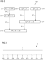
- FIG 2 a flow chart 200 is shown which illustrates a method for validating a function of a sensor unit 7 of a rail vehicle 6 for object localization according to an embodiment of the invention.
- a reference position RP T of a test object 3 is determined by a first self-localization unit 4.
- a satellite signal PS is received by the first self-localization unit 4, in this embodiment a satellite navigation unit.
- step 2.II the determined reference position RP T of the test object 3 is transmitted to a receiving unit 11 of the rail vehicle 6 by a transmitting unit 5 arranged on the test object 3.
- step 2.III a relative position RLP of the test object 3 to a sensor unit 7 arranged on the rail vehicle 6 is detected.
- the sensor unit 7 measures in the FIG 2 illustrated embodiment, a lidar unit, a distance and an azimuth of the test object 3 relative to the orientation of the sensor unit 7.
- an ego position EP of the rail vehicle 6 is additionally determined by a second self-localization unit 9 arranged on the rail vehicle 6.
- the orientation of the rail vehicle 6 is also known based on the known geometry of the test rail section 2, for example the test rail section 2 runs in a straight line.
- step 2.V an absolute position AP of the test object 3 is determined on the basis of the detected relative position RLP of the test object 3 to the sensor unit 7 and the determined ego position EP as well as the known orientation of the rail vehicle 6.
- step 2.VI the object localization function of the sensor unit 7 is validated by determining a deviation AW of the determined absolute position AP of the test object 3 from the reference position RP T of the test object 3.
- FIG 3 shows a schematic representation of a process for creating a map with ego positions EP1, ..., EP8, which the rail vehicle 6 (see FIG 1 ) as part of the validation.
- the ego positions EP1, EP2 ..., EP8 are located at different positions on the test track section 2. Therefore, the distances d l (see FIG 1 ) between the test object 3 and the rail vehicle 6 at the different ego positions EP1, ..., EP8 also vary.
- measurement accuracies can be determined as a function of distances or intervals d l and it can be established up to which distance the sensor unit 7 meets the minimum requirements for measurement accuracy.
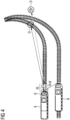
- FIG 4 is a representation of the possible errors in determining the ego position EP of a rail vehicle 6 and their effects on object localization.
- An inaccurate determination or a deviation ⁇ L of the ego position EP of the rail vehicle 6 in the longitudinal L and a deviation ⁇ Lat in the lateral Lat can lead to false positive or false negative results.
- FIG 4 an example is shown in which an object O is actually on a rail line, but is falsely located outside the rail area due to a deviation in the determination of the ego position EP of the rail vehicle 6. This shift results from the deviation ⁇ L of the measured ego position EP of the rail vehicle 6 from its true ego position.
- the correct classification of the detected object O depends not only on the correct determination of the ego position EP of the rail vehicle 6 but also on the correct determination of the relative position RLP of the object O from the rail vehicle 6. Both deviations are ultimately included in the validation, since both the ego position EP of the rail vehicle 6 and the relative position RLP are the ones with the true position of the object O, in the case of validation with the test object 3 this is the reference position RP T of the test object 3 (see FIG 1 ), influence the absolute position AP of the object O to be compared.
- FIG 5 shows a representation of positions of objects O with different lateral distances to a center line 2a of a rail line 6.
- the center line 2a is composed of straight line sections STA, which approximate the true course of the line marked by curves.
- FIG 6 is a diagram that illustrates a determination of the minimum distance between a point P with the coordinates (x 0 , y 0 ) and a constructed line STA with the points Q and Q' with the coordinates (x 1 , y 1 ) and (x 2 , y 2 ).
- the distance d between the point P and the line y ⁇ a b x ⁇ c b
- the line segment with the points Q and Q' is defined by the vector r
- the smallest distance d r is the projection of the vector r on the vector v .
- the distance d r between the point P and the line y ⁇ a b x ⁇ c b
- d r x 2 ⁇ x 1 y 1 ⁇ y 0 ⁇ x 1 ⁇ x 0 y 2 ⁇ y 1 x 2 ⁇ x 1 2 + y 2 ⁇ y 1 2
- FIG 7 is a diagram which illustrates the determination of a longitudinal distance d l between a point P 0 with the coordinates (x 0 , y 0 ) and an auxiliary point P' with the coordinates (x r ', y r ') on the constructed line STA in the longitudinal direction.
- a longitudinal distance d r calculated perpendicular to the line y
- the spanning hypotenuse d 0 is first calculated.
- the longitudinal distance d l is then obtained as the leg of the triangle from the other two known distances d r , d 0 .
- FIG 8 a circular distance on a sphere between a point P and P 0 is shown.
- the distance between two given points on a sphere can be calculated using the so-called Haversine formula.
- Haversine formula the distance between two points whose geocoordinates are known can be easily calculated.
- FIG 9 is a representation of angular relationships in a unit circle.
- the points A, B and the center O' form an isosceles triangle whose legs have the length 1.
- One of the legs, the height h of the isosceles triangle and half the base of the isosceles triangle form a right-angled triangle with the leg with the unit length 1 as the hypotenuse and the angle ⁇ between the leg of the isosceles triangle and the height h.
- the base of the isosceles triangle is divided into two equal halves at the foot point C. If the height h is extended in the x direction, the extended half line intersects the unit circle at point D.
- the function value sin ⁇ is formed by half the base of the isosceles triangle.
- the opposite side d l and thus the longitudinal distance d l can be calculated from the hypotenuse d 0 and the lateral distance d r .
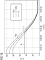
- FIG 10 a diagram is shown which documents a validation process.
- a solid step-shaped line shows measured values, in this case measured longitudinal distances d l in meters (abbreviated to "m") between a rail vehicle 6 or a sensor unit 7 arranged at the front of the rail vehicle 6 and a test object 3 as a function of the measurement time t (the time is given in coordinated universal time, "UTC").
- reference values d lref for a longitudinal distance between the rail vehicle 6 or the sensor unit 7 and the test object 3, which are determined by measuring the self-localization units 4, 9 of the test object 3 and the rail vehicle 6, are also shown in the diagram with a solid line.
- a tolerance range T with a maximum deviation of the measured longitudinal distances d l of 10% from the respective reference value d lref is marked with dashed lines.
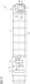
- FIG 11 is a schematic representation of an arrangement 1 for validating a function of a sensor unit 7 of a rail vehicle 6 for object localization according to a second embodiment of the invention.
- FIG 11 In the arrangement 1 shown, it is not the rail vehicle 6 but the test object 3 that has the validation unit 10.
- the test object 3 includes, unlike in the FIG 1
- the first embodiment shown has a receiving unit 5' for receiving the absolute position AP of the test object 3 determined by the position determination unit 8.
- the rail vehicle 6 has a transmitting unit 11' for transmitting the absolute position AP of the test object 3 determined by the position determination unit 8 to the test object 3.
- a single validation unit 10 can be used for validating different rail vehicles, thereby achieving a resource-saving effect.
- the test object 3 also has, as in the FIG 1
- the first embodiment shown has a first self-localization unit 4 which transmits a determined reference position RP T of the test object 3 directly to the validation unit 10 comprised by the test object 3.
- FIG 12 is a schematic representation of an arrangement 1 for validating a function of a sensor unit 7 of a rail vehicle 6 for object localization according to a third embodiment of the invention.
- the arrangement 1 has a stationary evaluation device 12 separate from the rail vehicle 6 and the test object 3.
- the stationary evaluation device 12 in this case comprises the validation unit 10 and a receiving unit 5'' for receiving the absolute position AP of the test object 3 determined by the position determination unit 8 of the rail vehicle 6.
- the receiving unit 5'' is also set up in the third embodiment to receive the reference position RP T of the test object 3 from the test object 3 and to forward the received information AP, RP T to the validation unit 10.
- the stationary evaluation device 12 can also be designed as a so-called remote computer and can be connected to the test object 3 and the rail vehicle 6 via a communication network, for example the Internet. to receive the measurement data or information AP, RP T determined by the test object 3 and the rail vehicle 6.
- the rail vehicle 6 has FIG 12
- the third embodiment shown has, similar to the second embodiment, a transmitting unit 11' for transmitting the absolute position AP of the test object 3 determined by the position determination unit 8 to the evaluation device 12.
- the test object 3 in the third embodiment is constructed analogously to the test object 3 of the first embodiment.
- the transmitting unit 5 of the test object 3 in the third embodiment does not transmit the information about the reference position RP T of the test object 3 to the rail vehicle 6, but to the separate stationary evaluation device 12.
Landscapes
- Engineering & Computer Science (AREA)
- Mechanical Engineering (AREA)
- Train Traffic Observation, Control, And Security (AREA)
- Length Measuring Devices With Unspecified Measuring Means (AREA)
- Electric Propulsion And Braking For Vehicles (AREA)
Claims (15)
- Agencement (1) de validation de la fonction d'une unité (7) de capteur d'un véhicule (6) ferroviaire pour la localisation d'objets, comportant :- une voie (2) ferrée de test,- un objet (3) de test sur la voie (2) ferrée de test, comprenant une première unité (4) d'autolocalisation pour la détermination d'une position (RPT) de référence de l'objet (3) de test,- le véhicule (6) ferroviaire, comprenant :- une unité (7) de capteur pour la détection d'une position (RLP) relative de l'objet (3) de test par rapport à l'unité (7) de capteur,- une deuxième unité (9) d'autolocalisation pour la détermination d'une position (EP) d'égo du véhicule (6) ferroviaire,- une unité (8) de détermination de position pour la détermination d'une position (AP) absolue de l'objet (3) de test sur la base de la position (RLP) relative détectée de l'objet (3) de test par rapport à l'unité (7) de capteur et de la position (EP) d'égo déterminée du véhicule (6) ferroviaire,- une unité (10) de validation pour la détermination d'un écart (AW) de la position (AP) absolue déterminée de l'objet (3) de test à la position (RPT) de référence de l'objet (3) de test.
- Agencement suivant la revendication 1, dans lequel l'objet (3) de test a une unité (5) d'émission pour la transmission de la position (RPT) de référence déterminée de l'objet (3) de test à l'unité (10) de validation.
- Agencement suivant l'une des revendications 1 ou 2, dans lequel le véhicule (6) ferroviaire comprend une unité (11) de réception pour la réception de la position (RPT) de référence déterminée de l'objet (3) de test.
- Agencement suivant l'une des revendications précédentes, dans lequel le véhicule (6) ferroviaire comprend l'unité (10) de validation.
- Agencement suivant la revendication 1, dans lequel- l'objet (3) de test a- l'unité (10) de validation et- une unité (5') de réception pour la réception de la position (AP) absolue, déterminée par l'unité (8) de détermination de position, de l'objet (3) de test
et- le véhicule (6) ferroviaire a une unité (11') d'émission pour la transmission de la position (AP) absolue, déterminée par l'unité (8) de détermination de position, de l'objet (3) de test. - Agencement suivant l'une des revendications 1 ou 2, comportant un dispositif (12) d'évaluation distinct du véhicule (6) ferroviaire et de l'objet (3) de test, comprenant :- l'unité (10) de validation,- une unité (5") de réception pour la réception de la position (AP) absolue, déterminée par l'unité (8) de détermination de position, de l'objet (3) de test et de la position (RPT) de référence de l'objet (3) de test,dans lequel le véhicule (6) ferroviaire a une unité (11') d'émission pour la transmission de la position (AP) absolue, déterminée par l'unité (8) de détermination de position, de l'objet (3) de test.
- Agencement suivant l'une des revendications précédentes, dans lequel la première et/ou la deuxième unités (4, 9) d'autolocalisation comprend au moins l'un des types suivants d'unités d'autolocalisation :- une unité de navigation pour la réception d'un signal de navigation par satellite,- une unité de réception pour la réception de données de correction RTK,- une unité de mesure inertielle.
- Agencement suivant l'une des revendications précédentes, dans lequel l'unité (8) de détermination de position est agencée pour déterminer, sur la base de la position (EP) d'égo du véhicule (6) ferroviaire, un chemin de la ligne (2a) centrale de la voie (2) ferrée de test.
- Agencement suivant la revendication 8, dans lequel- l'unité (8) de détermination de position est agencée pour déterminer une distance (dr) de l'objet (3) de test à la ligne (2a) centrale, et- l'unité (10) de validation est agencée pour déterminer un écart (AW) de la distance (dr), déterminée de l'objet (3) de test à la ligne (2a) centrale, à une distance de l'objet (3) de test à la ligne (2a) centrale.
- Agencement suivant l'une des revendications précédentes, dans lequel- l'unité (8) de détermination de position est agencée pour déterminer une distance (d1) longitudinale entre le véhicule (6) ferroviaire et l'objet (3) de test, et- l'unité (10) de validation est agencée pour déterminer un écart (AW) entre la distance (d1) longitudinale détectée entre le véhicule (6) ferroviaire et l'objet (3) de test et une distance (d1ref) de référence longitudinale, détectée sur la base de la position (RPT) de référence de l'objet (3) de test et de la position (EP) d'égo déterminée du véhicule (6) ferroviaire, entre le véhicule (6) ferroviaire et l'objet (3) de test.
- Agencement suivant l'une des revendications précédentes, dans lequel la voie (2) ferrée de test a un tracé en ligne droite.
- Agencement suivant l'une des revendications précédentes, dans lequel la voie (2) ferrée de test comprend un tracé curviligne et une ligne (2a) centrale de la voie (2) ferrée de test est approchée des voies partielles en ligne droite.
- Procédé de validation de la fonction d'une unité (7) de capteur d'un véhicule (6) ferroviaire pour la localisation d'objet, comprenant les stades :- détermination d'une position (RPT) de référence d'un objet (3) de test par une première unité (4) d'autolocalisation montée sur l'objet (3) de test,- détection d'une position (RLP) relative de l'objet (3) de test par rapport à une unité (7) de capteur montée sur le véhicule (6) ferroviaire,- détermination d'une position (EP) d'égo du véhicule (6) ferroviaire par une deuxième unité (9) d'autolocalisation montée sur le véhicule (6) ferroviaire,- détermination d'une position (AP) absolue de l'objet (3) de test sur la base de la position (RLP) relative détectée de l'objet (3) de test par rapport à l'unité (7) de capteur et de la position (EP) d'égo déterminée du véhicule (6) ferroviaire,- validation d'une localisation d'objet de l'unité (7) de capteur par détermination d'un écart (AW) de la position (AP) absolue déterminée de l'objet (3) de test à la position (RPT) de référence de l'objet (3) de test.
- Produit de programme d'ordinateur, comprenant des instructions, qui, lors de l'exécution du programme par un ordinateur, font que celles-ci exécutent les stades de la détermination d'une position (AP) absolue de l'objet (3) de test et de la validation de la localisation d'objet du procédé suivant la revendication 13.
- Support de mémoire, déchiffrable par ordinateur, comprenant des instructions, qui, lors de l'exécution par un ordinateur, font que celles-ci exécutent les stades de la détermination d'une position (AP) de l'objet (3) de test et de la validation de la localisation d'objet du procédé suivant la revendication 13.
Applications Claiming Priority (1)
| Application Number | Priority Date | Filing Date | Title |
|---|---|---|---|
| DE102022205527.6A DE102022205527A1 (de) | 2022-05-31 | 2022-05-31 | Validierung einer Sensoreinheit eines Schienenfahrzeugs zur Objektlokalisierung |
Publications (2)
| Publication Number | Publication Date |
|---|---|
| EP4286243A1 EP4286243A1 (fr) | 2023-12-06 |
| EP4286243B1 true EP4286243B1 (fr) | 2025-01-22 |
Family
ID=85285303
Family Applications (1)
| Application Number | Title | Priority Date | Filing Date |
|---|---|---|---|
| EP23157523.4A Active EP4286243B1 (fr) | 2022-05-31 | 2023-02-20 | Validation d'une unité de détection d'un véhicule ferroviaire pour la localisation d'objets |
Country Status (3)
| Country | Link |
|---|---|
| EP (1) | EP4286243B1 (fr) |
| DE (1) | DE102022205527A1 (fr) |
| ES (1) | ES3023593T3 (fr) |
Families Citing this family (2)
| Publication number | Priority date | Publication date | Assignee | Title |
|---|---|---|---|---|
| DE102023204214A1 (de) * | 2023-05-08 | 2024-11-14 | Siemens Mobility GmbH | Validierung einer Objekterkennungseinrichtung eines Schienenfahrzeugs |
| DE102023204912A1 (de) * | 2023-05-25 | 2024-11-28 | Siemens Mobility GmbH | Dynamische Validierung einer Funktion einer Sensoreinheit eines Schienenfahrzeugs zur Objektlokalisierung |
Family Cites Families (6)
| Publication number | Priority date | Publication date | Assignee | Title |
|---|---|---|---|---|
| DE102006007788A1 (de) * | 2006-02-20 | 2007-08-30 | Siemens Ag | Verfahren zur rechnergestützten Überwachung des Betriebs eines einen vorgegebenen Streckenverlauf fahrenden Fahrzeugs, insbesondere eines spurgebundenen Schienenfahrzeugs |
| DE102017111860A1 (de) * | 2017-05-31 | 2018-12-06 | Valeo Schalter Und Sensoren Gmbh | Verfahren zum Kalibrieren eines Radarsensors eines Kraftfahrzeugs während einer Bewegung des Kraftfahrzeugs, Radarsensor, Fahrerassistenzsystem sowie Kraftfahrzeug |
| US20190162820A1 (en) | 2017-11-29 | 2019-05-30 | Delphi Technologies, Llc | Automated vehicle sensor calibration system |
| DE102019206021A1 (de) | 2019-04-26 | 2020-10-29 | Robert Bosch Gmbh | Verfahren zur Erkennung einer Funktionsfähigkeit eines Umgebungssensors, Steuergerät und Fahrzeug |
| DE102019206503A1 (de) | 2019-05-07 | 2020-11-12 | Zf Friedrichshafen Ag | Verfahren und Steuereinheit zum Betreiben eines autonomen Fahrzeugs |
| DE102020212374A1 (de) | 2020-09-30 | 2022-03-31 | Siemens Mobility GmbH | Verfahren zur Überprüfung der Kalibrierung eines auf einem Schienenfahrzeug angeordneten Umfeldsensors |
-
2022
- 2022-05-31 DE DE102022205527.6A patent/DE102022205527A1/de not_active Withdrawn
-
2023
- 2023-02-20 EP EP23157523.4A patent/EP4286243B1/fr active Active
- 2023-02-20 ES ES23157523T patent/ES3023593T3/es active Active
Also Published As
| Publication number | Publication date |
|---|---|
| DE102022205527A1 (de) | 2023-11-30 |
| EP4286243A1 (fr) | 2023-12-06 |
| ES3023593T3 (en) | 2025-06-02 |
Similar Documents
| Publication | Publication Date | Title |
|---|---|---|
| DE3686213T2 (de) | Navigationseinrichtung. | |
| DE102012014397B4 (de) | Verfahren zum Ermitteln einer Position eines Fahrzeugs und Fahrzeug | |
| EP3746346B1 (fr) | Véhicule ferroviaire et procédé de mesure d'une voie ferrée | |
| DE102015219551B4 (de) | Objekterfassungsvorrichtung | |
| DE112018008222T5 (de) | Bewegungsplan-erzeugungseinrichtung und autonomes fahrsystem | |
| DE102008029613A1 (de) | Verfahren zur Schätzung der Elevation eines Zielobjekts unter Verwendung einer Radar-Datenfusion | |
| EP4286243B1 (fr) | Validation d'une unité de détection d'un véhicule ferroviaire pour la localisation d'objets | |
| EP3060942B1 (fr) | Procédé pour la détermination de la disposition d'au moins deux capteurs et réseaux de capteurs | |
| DE102012006738A1 (de) | Verfahren zur Kontrolle einer Gruppe von Objekten | |
| DE112014001069T5 (de) | Steuerungssystem und -verfahren zur Steuerung eines Fahrzeugs im Zusammenhang mit der Erkennung eines Hindernisses | |
| DE102016221440A1 (de) | Verfahren zur Diagnose von Umfeld-Sensorsystemen in Fahrzeugen | |
| DE102016121928A1 (de) | Fahrzeugnavigationssystem mit Positionsunterstützung von Nachbarfahrzeugen | |
| DE102021204372A1 (de) | Orientierungsbasierte Positionsermittlung von Schienenfahrzeugen | |
| DE3538908A1 (de) | Bordautonomes ortungssystem fuer positionsermittlung und kollisionsschutz von roboter- und flurfoerderfahrzeugen | |
| DE102018221864A1 (de) | Verfahren und System zum Bestimmen einer Trajektorie eines Fahrzeugs | |
| EP3395632A1 (fr) | Système de transport automatique et collaboratif sans conducteur | |
| EP2756265A1 (fr) | Dispositif et procédé pour déterminer une position d'un véhicule | |
| EP3859367B1 (fr) | Système de sécurité et procédé de localisation | |
| EP4029758A1 (fr) | Surveillance embarquée à sécurité critique de l'environnement d'un véhicule ferroviaire | |
| EP2995971A1 (fr) | Procede et systeme de determination de la position | |
| DE102017220004A1 (de) | Verfahren und Fahrerassistenzsystem zum Regeln der Fahrdynamik eines Fahrzeugs | |
| WO2020229140A1 (fr) | Détermination de la vitesse d'objets et de leur distance à un système de capteurs | |
| DE102004050690A1 (de) | Verfahren, Computer-Programm mit Programm-Code-Mitteln, Computer-Programm-Produkt und Gerät zur Modellierung der Umwelt eines autonomen mobilen Systems | |
| EP3658953B1 (fr) | Dispositif et procédé de reconnaissance de la hauteur d'un objet | |
| EP3326891B1 (fr) | Procédé de localisation d'un véhicule le long d'une route dans un environnement de stationnement |
Legal Events
| Date | Code | Title | Description |
|---|---|---|---|
| PUAI | Public reference made under article 153(3) epc to a published international application that has entered the european phase |
Free format text: ORIGINAL CODE: 0009012 |
|
| STAA | Information on the status of an ep patent application or granted ep patent |
Free format text: STATUS: THE APPLICATION HAS BEEN PUBLISHED |
|
| AK | Designated contracting states |
Kind code of ref document: A1 Designated state(s): AL AT BE BG CH CY CZ DE DK EE ES FI FR GB GR HR HU IE IS IT LI LT LU LV MC ME MK MT NL NO PL PT RO RS SE SI SK SM TR |
|
| STAA | Information on the status of an ep patent application or granted ep patent |
Free format text: STATUS: REQUEST FOR EXAMINATION WAS MADE |
|
| 17P | Request for examination filed |
Effective date: 20240603 |
|
| RBV | Designated contracting states (corrected) |
Designated state(s): AL AT BE BG CH CY CZ DE DK EE ES FI FR GB GR HR HU IE IS IT LI LT LU LV MC ME MK MT NL NO PL PT RO RS SE SI SK SM TR |
|
| GRAP | Despatch of communication of intention to grant a patent |
Free format text: ORIGINAL CODE: EPIDOSNIGR1 |
|
| STAA | Information on the status of an ep patent application or granted ep patent |
Free format text: STATUS: GRANT OF PATENT IS INTENDED |
|
| INTG | Intention to grant announced |
Effective date: 20241010 |
|
| GRAS | Grant fee paid |
Free format text: ORIGINAL CODE: EPIDOSNIGR3 |
|
| GRAA | (expected) grant |
Free format text: ORIGINAL CODE: 0009210 |
|
| STAA | Information on the status of an ep patent application or granted ep patent |
Free format text: STATUS: THE PATENT HAS BEEN GRANTED |
|
| AK | Designated contracting states |
Kind code of ref document: B1 Designated state(s): AL AT BE BG CH CY CZ DE DK EE ES FI FR GB GR HR HU IE IS IT LI LT LU LV MC ME MK MT NL NO PL PT RO RS SE SI SK SM TR |
|
| REG | Reference to a national code |
Ref country code: GB Ref legal event code: FG4D Free format text: NOT ENGLISH |
|
| REG | Reference to a national code |
Ref country code: CH Ref legal event code: EP |
|
| REG | Reference to a national code |
Ref country code: IE Ref legal event code: FG4D Free format text: LANGUAGE OF EP DOCUMENT: GERMAN |
|
| REG | Reference to a national code |
Ref country code: DE Ref legal event code: R096 Ref document number: 502023000476 Country of ref document: DE |
|
| REG | Reference to a national code |
Ref country code: NL Ref legal event code: MP Effective date: 20250122 |
|
| REG | Reference to a national code |
Ref country code: ES Ref legal event code: FG2A Ref document number: 3023593 Country of ref document: ES Kind code of ref document: T3 Effective date: 20250602 |
|
| PG25 | Lapsed in a contracting state [announced via postgrant information from national office to epo] |
Ref country code: NL Free format text: LAPSE BECAUSE OF FAILURE TO SUBMIT A TRANSLATION OF THE DESCRIPTION OR TO PAY THE FEE WITHIN THE PRESCRIBED TIME-LIMIT Effective date: 20250122 |
|
| PG25 | Lapsed in a contracting state [announced via postgrant information from national office to epo] |
Ref country code: RS Free format text: LAPSE BECAUSE OF FAILURE TO SUBMIT A TRANSLATION OF THE DESCRIPTION OR TO PAY THE FEE WITHIN THE PRESCRIBED TIME-LIMIT Effective date: 20250422 |
|
| PG25 | Lapsed in a contracting state [announced via postgrant information from national office to epo] |
Ref country code: FI Free format text: LAPSE BECAUSE OF FAILURE TO SUBMIT A TRANSLATION OF THE DESCRIPTION OR TO PAY THE FEE WITHIN THE PRESCRIBED TIME-LIMIT Effective date: 20250122 |
|
| PG25 | Lapsed in a contracting state [announced via postgrant information from national office to epo] |
Ref country code: PL Free format text: LAPSE BECAUSE OF FAILURE TO SUBMIT A TRANSLATION OF THE DESCRIPTION OR TO PAY THE FEE WITHIN THE PRESCRIBED TIME-LIMIT Effective date: 20250122 |
|
| PGFP | Annual fee paid to national office [announced via postgrant information from national office to epo] |
Ref country code: DE Payment date: 20250417 Year of fee payment: 3 |
|
| PGFP | Annual fee paid to national office [announced via postgrant information from national office to epo] |
Ref country code: ES Payment date: 20250520 Year of fee payment: 3 |
|
| REG | Reference to a national code |
Ref country code: LT Ref legal event code: MG9D |
|
| PG25 | Lapsed in a contracting state [announced via postgrant information from national office to epo] |
Ref country code: NO Free format text: LAPSE BECAUSE OF FAILURE TO SUBMIT A TRANSLATION OF THE DESCRIPTION OR TO PAY THE FEE WITHIN THE PRESCRIBED TIME-LIMIT Effective date: 20250422 Ref country code: IS Free format text: LAPSE BECAUSE OF FAILURE TO SUBMIT A TRANSLATION OF THE DESCRIPTION OR TO PAY THE FEE WITHIN THE PRESCRIBED TIME-LIMIT Effective date: 20250522 |
|
| PG25 | Lapsed in a contracting state [announced via postgrant information from national office to epo] |
Ref country code: HR Free format text: LAPSE BECAUSE OF FAILURE TO SUBMIT A TRANSLATION OF THE DESCRIPTION OR TO PAY THE FEE WITHIN THE PRESCRIBED TIME-LIMIT Effective date: 20250122 |
|
| PG25 | Lapsed in a contracting state [announced via postgrant information from national office to epo] |
Ref country code: PT Free format text: LAPSE BECAUSE OF FAILURE TO SUBMIT A TRANSLATION OF THE DESCRIPTION OR TO PAY THE FEE WITHIN THE PRESCRIBED TIME-LIMIT Effective date: 20250522 Ref country code: LV Free format text: LAPSE BECAUSE OF FAILURE TO SUBMIT A TRANSLATION OF THE DESCRIPTION OR TO PAY THE FEE WITHIN THE PRESCRIBED TIME-LIMIT Effective date: 20250122 |
|
| PG25 | Lapsed in a contracting state [announced via postgrant information from national office to epo] |
Ref country code: BG Free format text: LAPSE BECAUSE OF FAILURE TO SUBMIT A TRANSLATION OF THE DESCRIPTION OR TO PAY THE FEE WITHIN THE PRESCRIBED TIME-LIMIT Effective date: 20250122 Ref country code: GR Free format text: LAPSE BECAUSE OF FAILURE TO SUBMIT A TRANSLATION OF THE DESCRIPTION OR TO PAY THE FEE WITHIN THE PRESCRIBED TIME-LIMIT Effective date: 20250423 |
|
| REG | Reference to a national code |
Ref country code: DE Ref legal event code: R081 Ref document number: 502023000476 Country of ref document: DE Owner name: SIEMENS MOBILITY GMBH, DE Free format text: FORMER OWNER: SIEMENS MOBILITY GMBH, 81739 MUENCHEN, DE |
|
| PG25 | Lapsed in a contracting state [announced via postgrant information from national office to epo] |
Ref country code: SE Free format text: LAPSE BECAUSE OF FAILURE TO SUBMIT A TRANSLATION OF THE DESCRIPTION OR TO PAY THE FEE WITHIN THE PRESCRIBED TIME-LIMIT Effective date: 20250122 |
|
| PG25 | Lapsed in a contracting state [announced via postgrant information from national office to epo] |
Ref country code: SM Free format text: LAPSE BECAUSE OF FAILURE TO SUBMIT A TRANSLATION OF THE DESCRIPTION OR TO PAY THE FEE WITHIN THE PRESCRIBED TIME-LIMIT Effective date: 20250122 |
|
| RAP4 | Party data changed (patent owner data changed or rights of a patent transferred) |
Owner name: SIEMENS MOBILITY GMBH |
|
| PG25 | Lapsed in a contracting state [announced via postgrant information from national office to epo] |
Ref country code: DK Free format text: LAPSE BECAUSE OF FAILURE TO SUBMIT A TRANSLATION OF THE DESCRIPTION OR TO PAY THE FEE WITHIN THE PRESCRIBED TIME-LIMIT Effective date: 20250122 |
|
| PG25 | Lapsed in a contracting state [announced via postgrant information from national office to epo] |
Ref country code: MC Free format text: LAPSE BECAUSE OF FAILURE TO SUBMIT A TRANSLATION OF THE DESCRIPTION OR TO PAY THE FEE WITHIN THE PRESCRIBED TIME-LIMIT Effective date: 20250122 |
|
| PG25 | Lapsed in a contracting state [announced via postgrant information from national office to epo] |
Ref country code: IT Free format text: LAPSE BECAUSE OF FAILURE TO SUBMIT A TRANSLATION OF THE DESCRIPTION OR TO PAY THE FEE WITHIN THE PRESCRIBED TIME-LIMIT Effective date: 20250122 Ref country code: LU Free format text: LAPSE BECAUSE OF NON-PAYMENT OF DUE FEES Effective date: 20250220 |
|
| PG25 | Lapsed in a contracting state [announced via postgrant information from national office to epo] |
Ref country code: EE Free format text: LAPSE BECAUSE OF FAILURE TO SUBMIT A TRANSLATION OF THE DESCRIPTION OR TO PAY THE FEE WITHIN THE PRESCRIBED TIME-LIMIT Effective date: 20250122 Ref country code: CZ Free format text: LAPSE BECAUSE OF FAILURE TO SUBMIT A TRANSLATION OF THE DESCRIPTION OR TO PAY THE FEE WITHIN THE PRESCRIBED TIME-LIMIT Effective date: 20250122 |
|
| REG | Reference to a national code |
Ref country code: DE Ref legal event code: R097 Ref document number: 502023000476 Country of ref document: DE |
|
| PG25 | Lapsed in a contracting state [announced via postgrant information from national office to epo] |
Ref country code: RO Free format text: LAPSE BECAUSE OF FAILURE TO SUBMIT A TRANSLATION OF THE DESCRIPTION OR TO PAY THE FEE WITHIN THE PRESCRIBED TIME-LIMIT Effective date: 20250122 |
|
| PG25 | Lapsed in a contracting state [announced via postgrant information from national office to epo] |
Ref country code: SK Free format text: LAPSE BECAUSE OF FAILURE TO SUBMIT A TRANSLATION OF THE DESCRIPTION OR TO PAY THE FEE WITHIN THE PRESCRIBED TIME-LIMIT Effective date: 20250122 |
|
| PLBE | No opposition filed within time limit |
Free format text: ORIGINAL CODE: 0009261 |
|
| STAA | Information on the status of an ep patent application or granted ep patent |
Free format text: STATUS: NO OPPOSITION FILED WITHIN TIME LIMIT |
|
| REG | Reference to a national code |
Ref country code: BE Ref legal event code: MM Effective date: 20250228 |
|
| 26N | No opposition filed |
Effective date: 20251023 |
|
| PG25 | Lapsed in a contracting state [announced via postgrant information from national office to epo] |
Ref country code: BE Free format text: LAPSE BECAUSE OF NON-PAYMENT OF DUE FEES Effective date: 20250228 |
|
| PG25 | Lapsed in a contracting state [announced via postgrant information from national office to epo] |
Ref country code: IE Free format text: LAPSE BECAUSE OF NON-PAYMENT OF DUE FEES Effective date: 20250220 |
|
| PGFP | Annual fee paid to national office [announced via postgrant information from national office to epo] |
Ref country code: AT Payment date: 20260301 Year of fee payment: 4 |
|
| PGFP | Annual fee paid to national office [announced via postgrant information from national office to epo] |
Ref country code: FR Payment date: 20260213 Year of fee payment: 4 |