EP4286596B1 - Schacht - Google Patents
Schacht Download PDFInfo
- Publication number
- EP4286596B1 EP4286596B1 EP23166774.2A EP23166774A EP4286596B1 EP 4286596 B1 EP4286596 B1 EP 4286596B1 EP 23166774 A EP23166774 A EP 23166774A EP 4286596 B1 EP4286596 B1 EP 4286596B1
- Authority
- EP
- European Patent Office
- Prior art keywords
- shaft
- head frame
- frame
- steel frame
- walls
- Prior art date
- Legal status (The legal status is an assumption and is not a legal conclusion. Google has not performed a legal analysis and makes no representation as to the accuracy of the status listed.)
- Active
Links
Images



Classifications
-
- E—FIXED CONSTRUCTIONS
- E02—HYDRAULIC ENGINEERING; FOUNDATIONS; SOIL SHIFTING
- E02D—FOUNDATIONS; EXCAVATIONS; EMBANKMENTS; UNDERGROUND OR UNDERWATER STRUCTURES
- E02D29/00—Independent underground or underwater structures; Retaining walls
- E02D29/12—Manhole shafts; Other inspection or access chambers; Accessories therefor
- E02D29/124—Shaft entirely made of synthetic material
-
- H—ELECTRICITY
- H02—GENERATION; CONVERSION OR DISTRIBUTION OF ELECTRIC POWER
- H02G—INSTALLATION OF ELECTRIC CABLES OR LINES, OR OF COMBINED OPTICAL AND ELECTRIC CABLES OR LINES
- H02G9/00—Installations of electric cables or lines in or on the ground or water
- H02G9/10—Installations of electric cables or lines in or on the ground or water in cable chambers, e.g. in manhole or in handhole
Definitions
- the invention relates to a shaft whose shaft walls consist of wall elements placed on top of one another, which are made of plastic by injection molding, according to the preamble of claim 1.
- the upper end of the shaft walls formed in this way contains a steel frame, which is usually a circumferential rectangular profile, on which one or more shaft covers are arranged, which are surrounded by a flat steel attached to the outside of the steel frame.
- the top edge of the flat steel and the top of the manhole cover(s) must be at the same height as the area around the shaft, as such a shaft is usually accessible and can be driven over.
- the steel frame can be supported on spindles, the length of which is adjusted so that the manhole cover(s) is/are exactly at the same level as the surrounding area.
- the manhole cover(s) may be subjected to great mechanical stress, the upper end of the manhole must be sufficiently stable.
- the present invention is based on the object of specifying a shaft of the type mentioned at the beginning, in which, in the case of a height adjustment with extended spindles, it is possible to check whether the associated measures have been carried out correctly. In particular, it should be possible to check whether all spindles have been extended correctly and whether the thin mortar introduced is sufficient to support the raised steel frame.
- the invention provides that a head frame is attached to the top of the shaft walls, which has a plate-shaped section that rests on the shaft walls and a formwork section that is angled upwards in the installation position and is arranged on the inside of the shaft walls in the installation position.
- the steel frame has a spindle that can be extended to compensate for the height of the steel frame, so that the steel frame rests either directly on the head frame or on extended spindles and a supporting layer of mortar arranged on the head frame.
- the invention provides that in the area of the spindles a recess is formed in the formwork section of the head frame, in which a viewing window is arranged that can be removed in order to be able to visually inspect the area of the spindle.
- the plate-shaped, removable viewing window has means on the edge, e.g. in the form of hooks, with which the viewing window can be attached to the edge of the window opening.
- the viewing window can also be made of a transparent material so that it does not have to be removed for inspection.
- the formwork section which preferably adjoins the plate-shaped section at an angle of 90°, reliably prevents the thin mortar from partially running into the interior of the shaft.
- a circumferential outer formwork is attached with clips to the opposite side of the shaft wall, which also prevents the mortar from running off there. This reduces the installation costs of the shaft.
- the head frame can be made up of several head frame parts that lie against one another or engage with one another at the corners of the generally rectangular shaft.
- the individual head frame parts can have hooks on a side edge section that are inserted into the associated shaft walls in order to initially position the head frame parts correctly on the shaft walls.
- the head frame parts can have locking lugs that snap into recesses in the shaft walls, whereby the entire head frame is fixed immovably on the top of the shaft walls.
- the head frame can advantageously have a holder for a support plate in the area of the viewing windows, on which an extended spindle is supported.
- the support plates can withstand a high support pressure that can be caused by traffic loads on the manhole cover.
- the head frame is preferably manufactured in one piece using a plastic injection molding process, preferably from PC.
- a plastic injection molding process preferably from PC.
- the plate-shaped section and the formwork section of the head frame can be assembled in a suitable manner as separately manufactured components.
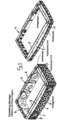
- Figure 1 shows a perspective view of a shaft whose shaft walls consist of three wall elements 1 placed on top of each other.
- the upper end of the shaft is formed by a head frame 2 and a steel frame 3 arranged above it, on which a surrounding flat steel 4 is fastened, in which two shaft covers 5 are arranged flush.
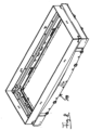
- Figure 2 shows a head frame 2 which is attached to the top of two wall elements 1 of different heights.
- the head frame 2 consists of four head frame parts 6 which are joined together at the corners of the rectangular shaft.
- the head frame parts 6 consist of a substantially plate-shaped section 7 which is attached to the associated shaft wall and a formwork section 8 which is angled upwards at a right angle and faces the inside of the shaft.
- recesses 9 are formed into which locking bolts of the shaft cover can enter.
- the recesses 9 can be releasably closed by means of plugged-on closure plates (not shown).
- a head frame part 6 which can be attached to the top of a shaft wall without the aid of tools.
- the head frame part 6 is provided with hooks 11 and locking lugs 12.
- the hooks 11 form clamping means which are pushed into the shaft wall from the outside of the shaft in order to initially position the head frame part 6 correctly on the top of the shaft wall.
- the locking lugs 12 engage in recesses in the shaft wall on the inside of the shaft, whereby the head frame part 6 or the entire head frame 2 is fixed immovably on the shaft wall by this locking.
- a recess 10 is formed in the formwork wall 8, into which a removable viewing window 13 can be inserted by sliding and locking into place.
- the viewing window is available in several views in the Figures 5A to 5C shown.
- a depression 14 is formed in the plate-shaped section 7 of the head frame 2, into which a support plate 18 is inserted, on which a spindle described further below is supported for adjusting the height of the steel frame 3.
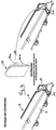
- FIG 4 In the left-hand illustration, the recess 10 in the formwork wall 8 is shown without a viewing window 13, whereby means for receiving hooks 14a, which are formed on the edge of the viewing window 13, are indicated on the edge of the recess 10.
- the viewing window 13 is mounted by inserting the viewing window 13 and locking it in place using the hooks 14a.
- the viewing window 13 In the right-hand illustration of the Figure 4 the viewing window 13 is shown in the inserted state.
- FIG. 5 details of the viewing window are shown, which contains a smooth closed surface 15, the edge of which is reinforced by a surrounding frame 16, on which hooks 14a are formed which project laterally beyond the surface 15.
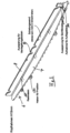
- Figure 6 shows a vertical section through the upper end of a shaft with the upper wall element 1.
- the head frame is attached to the top of the wall element 1 by the hooks 11 of the plate-shaped section 7 of the head frame 2 being inserted into the wall element 1 in a clamping manner.
- the steel frame 3 there is an end cap with a spindle 17, which in the illustration of the Figure 6 is extended downwards to compensate for the height and is supported on a support plate 18 arranged in the recess 14. This raises the steel frame 3 to such an extent that the top of the manhole cover 5 arranged on the steel frame 3 and the upper edge of the steel sheet 4 surrounding the cover 5 match the surrounding level.
- the resulting gap between the lower edge of the steel frame 3 and the plate-shaped section 7 of the head frame 2 must be filled with mortar.
- Figure 6 also shows a viewing window 13 in the head frame part 6 offset by 90°, which is removed in order to be able to check the area of the spindle offset by 90°.
- the principle diagram of the Figure 7 shows the view of a spindle 17 after removing a viewing window.
- the compensation at the surrounding level is indicated by two arrows H, whereby this gap is filled with mortar.
- FIG 8 a surrounding outer formwork 19 is shown, which complements the inner formwork wall 8 so that no mortar can escape on either side.
- the outer formwork 19 is assembled by plugging the individual sheet metal parts together and by fixing the entire outer formwork using so-called Christmas tree clips at the upper end area of the wall element 1.
Landscapes
- Engineering & Computer Science (AREA)
- Environmental & Geological Engineering (AREA)
- Life Sciences & Earth Sciences (AREA)
- General Life Sciences & Earth Sciences (AREA)
- Mining & Mineral Resources (AREA)
- Paleontology (AREA)
- Civil Engineering (AREA)
- General Engineering & Computer Science (AREA)
- Structural Engineering (AREA)
- Forms Removed On Construction Sites Or Auxiliary Members Thereof (AREA)
Applications Claiming Priority (1)
| Application Number | Priority Date | Filing Date | Title |
|---|---|---|---|
| DE102022114132.2A DE102022114132A1 (de) | 2022-06-03 | 2022-06-03 | Schacht |
Publications (2)
| Publication Number | Publication Date |
|---|---|
| EP4286596A1 EP4286596A1 (de) | 2023-12-06 |
| EP4286596B1 true EP4286596B1 (de) | 2025-02-19 |
Family
ID=85979557
Family Applications (1)
| Application Number | Title | Priority Date | Filing Date |
|---|---|---|---|
| EP23166774.2A Active EP4286596B1 (de) | 2022-06-03 | 2023-04-05 | Schacht |
Country Status (4)
| Country | Link |
|---|---|
| EP (1) | EP4286596B1 (da) |
| DE (1) | DE102022114132A1 (da) |
| DK (1) | DK4286596T3 (da) |
| PL (1) | PL4286596T3 (da) |
Family Cites Families (4)
| Publication number | Priority date | Publication date | Assignee | Title |
|---|---|---|---|---|
| DE10314897B3 (de) * | 2003-04-01 | 2004-10-14 | Lic Langmatz Gmbh | System zur Unterbringung von Verteilereinrichtungen von Kupfer- und/oder Glasfaserkabeln |
| EP1587199B1 (de) * | 2004-04-16 | 2011-12-21 | Langmatz GmbH | System zur Unterbringung von Verteilereinrichtungen von Kupfer- und/oder Glasfaserkabeln |
| DE202007014465U1 (de) * | 2007-10-16 | 2007-12-20 | Frei Netzwerk Ausstattung Gmbh | Unterflurschacht |
| DE102011116874B4 (de) * | 2011-10-25 | 2019-03-14 | Langmatz Gmbh | Schacht |
-
2022
- 2022-06-03 DE DE102022114132.2A patent/DE102022114132A1/de active Pending
-
2023
- 2023-04-05 DK DK23166774.2T patent/DK4286596T3/da active
- 2023-04-05 EP EP23166774.2A patent/EP4286596B1/de active Active
- 2023-04-05 PL PL23166774.2T patent/PL4286596T3/pl unknown
Also Published As
| Publication number | Publication date |
|---|---|
| DE102022114132A1 (de) | 2023-12-14 |
| EP4286596A1 (de) | 2023-12-06 |
| PL4286596T3 (pl) | 2025-06-23 |
| DK4286596T3 (da) | 2025-05-19 |
Similar Documents
| Publication | Publication Date | Title |
|---|---|---|
| DE102007012079B4 (de) | Verteilerschrank mit mehreren Innengehäusen | |
| EP1597804B1 (de) | Überstülpbarer verteilerschrank | |
| EP1811625B1 (de) | Bodenplatte sowie Kabelverteilerschrank mit Bodenplatte | |
| EP2669451A2 (de) | Tragkonstruktion und Verfahren zur Montage einer Tragkonstruktion | |
| EP2453544A2 (de) | Unterflur-Schacht | |
| EP3566270A1 (de) | Montageplattenanordnung und ein entsprechendes verfahren | |
| EP0563449A1 (de) | Gehäuse, insbesondere Kabelverzweigergehäuse | |
| EP4286596B1 (de) | Schacht | |
| DE102004033976B4 (de) | Dachmodul-Bausatz | |
| EP3612703B1 (de) | Montagekelle für den einbau von fensterbänken und verfahren zur montage einer fensterbank mit dieser montagekelle | |
| DE102014119021A1 (de) | Anordnung zum Befestigen eines Pfostens aus Kunststoff an einer Rahmenleiste eines Fensters oder einer Türe mittels eines Pfostenverbinders | |
| EP2878056B1 (de) | Unterirdischer schaltschrank für die elektroinstallation | |
| DE10144028A1 (de) | Maschinengestell in Modulbauweise | |
| DE19524103C2 (de) | Säule | |
| DE102015122535A1 (de) | Schalungseinrichtung, Schalungssystem, Einbausystem sowie ein Verfahren zur Herstellung eines Bodens | |
| DE202014102310U1 (de) | Sockel für mindestens ein Montagemodul | |
| EP1918467A1 (de) | Revisionsschacht für Spülkasten | |
| EP4286595B1 (de) | Schacht | |
| DE2936963A1 (de) | Einbaudose fuer elektrische installationsgeraete | |
| EP1352456B1 (de) | Gehäuse, insbesondere für den einbau elektrischer und elektronischer bauteile | |
| DE102018003189A1 (de) | Haltevorrichtung zur einschieb- und ausziehbaren Lagerung eines Umformers in einem Schaltschrank | |
| EP4693775A1 (de) | Modularer eingrabsockel und modularer verteilerkasten | |
| DE10328405B4 (de) | Schaltschrank | |
| DE102024122555A1 (de) | Modularer Eingrabsockel und modularer Verteilerkasten | |
| DE20303064U1 (de) | Überstülpbarer Verteilerschrank |
Legal Events
| Date | Code | Title | Description |
|---|---|---|---|
| PUAI | Public reference made under article 153(3) epc to a published international application that has entered the european phase |
Free format text: ORIGINAL CODE: 0009012 |
|
| STAA | Information on the status of an ep patent application or granted ep patent |
Free format text: STATUS: THE APPLICATION HAS BEEN PUBLISHED |
|
| AK | Designated contracting states |
Kind code of ref document: A1 Designated state(s): AL AT BE BG CH CY CZ DE DK EE ES FI FR GB GR HR HU IE IS IT LI LT LU LV MC ME MK MT NL NO PL PT RO RS SE SI SK SM TR |
|
| STAA | Information on the status of an ep patent application or granted ep patent |
Free format text: STATUS: REQUEST FOR EXAMINATION WAS MADE |
|
| P01 | Opt-out of the competence of the unified patent court (upc) registered |
Effective date: 20231208 |
|
| 17P | Request for examination filed |
Effective date: 20231215 |
|
| RBV | Designated contracting states (corrected) |
Designated state(s): AL AT BE BG CH CY CZ DE DK EE ES FI FR GB GR HR HU IE IS IT LI LT LU LV MC ME MK MT NL NO PL PT RO RS SE SI SK SM TR |
|
| GRAP | Despatch of communication of intention to grant a patent |
Free format text: ORIGINAL CODE: EPIDOSNIGR1 |
|
| STAA | Information on the status of an ep patent application or granted ep patent |
Free format text: STATUS: GRANT OF PATENT IS INTENDED |
|
| RIC1 | Information provided on ipc code assigned before grant |
Ipc: H02G 9/10 20060101ALI20241108BHEP Ipc: E02D 29/12 20060101AFI20241108BHEP |
|
| INTG | Intention to grant announced |
Effective date: 20241120 |
|
| GRAS | Grant fee paid |
Free format text: ORIGINAL CODE: EPIDOSNIGR3 |
|
| GRAA | (expected) grant |
Free format text: ORIGINAL CODE: 0009210 |
|
| STAA | Information on the status of an ep patent application or granted ep patent |
Free format text: STATUS: THE PATENT HAS BEEN GRANTED |
|
| AK | Designated contracting states |
Kind code of ref document: B1 Designated state(s): AL AT BE BG CH CY CZ DE DK EE ES FI FR GB GR HR HU IE IS IT LI LT LU LV MC ME MK MT NL NO PL PT RO RS SE SI SK SM TR |
|
| REG | Reference to a national code |
Ref country code: GB Ref legal event code: FG4D Free format text: NOT ENGLISH |
|
| REG | Reference to a national code |
Ref country code: CH Ref legal event code: EP |
|
| REG | Reference to a national code |
Ref country code: IE Ref legal event code: FG4D Free format text: LANGUAGE OF EP DOCUMENT: GERMAN |
|
| REG | Reference to a national code |
Ref country code: DE Ref legal event code: R096 Ref document number: 502023000573 Country of ref document: DE |
|
| REG | Reference to a national code |
Ref country code: DK Ref legal event code: T3 Effective date: 20250516 |
|
| REG | Reference to a national code |
Ref country code: NL Ref legal event code: MP Effective date: 20250219 |
|
| PG25 | Lapsed in a contracting state [announced via postgrant information from national office to epo] |
Ref country code: RS Free format text: LAPSE BECAUSE OF FAILURE TO SUBMIT A TRANSLATION OF THE DESCRIPTION OR TO PAY THE FEE WITHIN THE PRESCRIBED TIME-LIMIT Effective date: 20250519 |
|
| PG25 | Lapsed in a contracting state [announced via postgrant information from national office to epo] |
Ref country code: FI Free format text: LAPSE BECAUSE OF FAILURE TO SUBMIT A TRANSLATION OF THE DESCRIPTION OR TO PAY THE FEE WITHIN THE PRESCRIBED TIME-LIMIT Effective date: 20250219 |
|
| PGFP | Annual fee paid to national office [announced via postgrant information from national office to epo] |
Ref country code: DE Payment date: 20250516 Year of fee payment: 3 |
|
| PG25 | Lapsed in a contracting state [announced via postgrant information from national office to epo] |
Ref country code: ES Free format text: LAPSE BECAUSE OF FAILURE TO SUBMIT A TRANSLATION OF THE DESCRIPTION OR TO PAY THE FEE WITHIN THE PRESCRIBED TIME-LIMIT Effective date: 20250219 |
|
| PGFP | Annual fee paid to national office [announced via postgrant information from national office to epo] |
Ref country code: DK Payment date: 20250526 Year of fee payment: 3 |
|
| REG | Reference to a national code |
Ref country code: LT Ref legal event code: MG9D |
|
| PG25 | Lapsed in a contracting state [announced via postgrant information from national office to epo] |
Ref country code: IS Free format text: LAPSE BECAUSE OF FAILURE TO SUBMIT A TRANSLATION OF THE DESCRIPTION OR TO PAY THE FEE WITHIN THE PRESCRIBED TIME-LIMIT Effective date: 20250619 Ref country code: NO Free format text: LAPSE BECAUSE OF FAILURE TO SUBMIT A TRANSLATION OF THE DESCRIPTION OR TO PAY THE FEE WITHIN THE PRESCRIBED TIME-LIMIT Effective date: 20250519 |
|
| PG25 | Lapsed in a contracting state [announced via postgrant information from national office to epo] |
Ref country code: NL Free format text: LAPSE BECAUSE OF FAILURE TO SUBMIT A TRANSLATION OF THE DESCRIPTION OR TO PAY THE FEE WITHIN THE PRESCRIBED TIME-LIMIT Effective date: 20250219 |
|
| PGFP | Annual fee paid to national office [announced via postgrant information from national office to epo] |
Ref country code: BE Payment date: 20250429 Year of fee payment: 3 |
|
| PG25 | Lapsed in a contracting state [announced via postgrant information from national office to epo] |
Ref country code: HR Free format text: LAPSE BECAUSE OF FAILURE TO SUBMIT A TRANSLATION OF THE DESCRIPTION OR TO PAY THE FEE WITHIN THE PRESCRIBED TIME-LIMIT Effective date: 20250219 |
|
| PG25 | Lapsed in a contracting state [announced via postgrant information from national office to epo] |
Ref country code: LV Free format text: LAPSE BECAUSE OF FAILURE TO SUBMIT A TRANSLATION OF THE DESCRIPTION OR TO PAY THE FEE WITHIN THE PRESCRIBED TIME-LIMIT Effective date: 20250219 Ref country code: PT Free format text: LAPSE BECAUSE OF FAILURE TO SUBMIT A TRANSLATION OF THE DESCRIPTION OR TO PAY THE FEE WITHIN THE PRESCRIBED TIME-LIMIT Effective date: 20250620 |
|
| PG25 | Lapsed in a contracting state [announced via postgrant information from national office to epo] |
Ref country code: BG Free format text: LAPSE BECAUSE OF FAILURE TO SUBMIT A TRANSLATION OF THE DESCRIPTION OR TO PAY THE FEE WITHIN THE PRESCRIBED TIME-LIMIT Effective date: 20250219 Ref country code: GR Free format text: LAPSE BECAUSE OF FAILURE TO SUBMIT A TRANSLATION OF THE DESCRIPTION OR TO PAY THE FEE WITHIN THE PRESCRIBED TIME-LIMIT Effective date: 20250520 |
|
| PGFP | Annual fee paid to national office [announced via postgrant information from national office to epo] |
Ref country code: AT Payment date: 20250721 Year of fee payment: 3 |
|
| PG25 | Lapsed in a contracting state [announced via postgrant information from national office to epo] |
Ref country code: SE Free format text: LAPSE BECAUSE OF FAILURE TO SUBMIT A TRANSLATION OF THE DESCRIPTION OR TO PAY THE FEE WITHIN THE PRESCRIBED TIME-LIMIT Effective date: 20250219 |
|
| PG25 | Lapsed in a contracting state [announced via postgrant information from national office to epo] |
Ref country code: SM Free format text: LAPSE BECAUSE OF FAILURE TO SUBMIT A TRANSLATION OF THE DESCRIPTION OR TO PAY THE FEE WITHIN THE PRESCRIBED TIME-LIMIT Effective date: 20250219 |
|
| PG25 | Lapsed in a contracting state [announced via postgrant information from national office to epo] |
Ref country code: IT Free format text: LAPSE BECAUSE OF FAILURE TO SUBMIT A TRANSLATION OF THE DESCRIPTION OR TO PAY THE FEE WITHIN THE PRESCRIBED TIME-LIMIT Effective date: 20250219 |
|
| PG25 | Lapsed in a contracting state [announced via postgrant information from national office to epo] |
Ref country code: EE Free format text: LAPSE BECAUSE OF FAILURE TO SUBMIT A TRANSLATION OF THE DESCRIPTION OR TO PAY THE FEE WITHIN THE PRESCRIBED TIME-LIMIT Effective date: 20250219 Ref country code: CZ Free format text: LAPSE BECAUSE OF FAILURE TO SUBMIT A TRANSLATION OF THE DESCRIPTION OR TO PAY THE FEE WITHIN THE PRESCRIBED TIME-LIMIT Effective date: 20250219 |
|
| PG25 | Lapsed in a contracting state [announced via postgrant information from national office to epo] |
Ref country code: RO Free format text: LAPSE BECAUSE OF FAILURE TO SUBMIT A TRANSLATION OF THE DESCRIPTION OR TO PAY THE FEE WITHIN THE PRESCRIBED TIME-LIMIT Effective date: 20250219 |
|
| PG25 | Lapsed in a contracting state [announced via postgrant information from national office to epo] |
Ref country code: SK Free format text: LAPSE BECAUSE OF FAILURE TO SUBMIT A TRANSLATION OF THE DESCRIPTION OR TO PAY THE FEE WITHIN THE PRESCRIBED TIME-LIMIT Effective date: 20250219 |
|
| REG | Reference to a national code |
Ref country code: DE Ref legal event code: R097 Ref document number: 502023000573 Country of ref document: DE |
|
| PG25 | Lapsed in a contracting state [announced via postgrant information from national office to epo] |
Ref country code: LU Free format text: LAPSE BECAUSE OF NON-PAYMENT OF DUE FEES Effective date: 20250405 |
|
| PG25 | Lapsed in a contracting state [announced via postgrant information from national office to epo] |
Ref country code: MC Free format text: LAPSE BECAUSE OF FAILURE TO SUBMIT A TRANSLATION OF THE DESCRIPTION OR TO PAY THE FEE WITHIN THE PRESCRIBED TIME-LIMIT Effective date: 20250219 |
|
| PLBE | No opposition filed within time limit |
Free format text: ORIGINAL CODE: 0009261 |
|
| STAA | Information on the status of an ep patent application or granted ep patent |
Free format text: STATUS: NO OPPOSITION FILED WITHIN TIME LIMIT |
|
| PG25 | Lapsed in a contracting state [announced via postgrant information from national office to epo] |
Ref country code: FR Free format text: LAPSE BECAUSE OF NON-PAYMENT OF DUE FEES Effective date: 20250419 |
|
| 26N | No opposition filed |
Effective date: 20251120 |
|
| PG25 | Lapsed in a contracting state [announced via postgrant information from national office to epo] |
Ref country code: IE Free format text: LAPSE BECAUSE OF NON-PAYMENT OF DUE FEES Effective date: 20250405 |
|
| PGFP | Annual fee paid to national office [announced via postgrant information from national office to epo] |
Ref country code: PL Payment date: 20260331 Year of fee payment: 4 |