EP4287403A1 - Antennenvorrichtung und kommunikationsverfahren - Google Patents
Antennenvorrichtung und kommunikationsverfahren Download PDFInfo
- Publication number
- EP4287403A1 EP4287403A1 EP21927260.6A EP21927260A EP4287403A1 EP 4287403 A1 EP4287403 A1 EP 4287403A1 EP 21927260 A EP21927260 A EP 21927260A EP 4287403 A1 EP4287403 A1 EP 4287403A1
- Authority
- EP
- European Patent Office
- Prior art keywords
- near field
- antenna
- transmit
- signal
- energy
- Prior art date
- Legal status (The legal status is an assumption and is not a legal conclusion. Google has not performed a legal analysis and makes no representation as to the accuracy of the status listed.)
- Pending
Links
Images




Classifications
-
- H—ELECTRICITY
- H01—ELECTRIC ELEMENTS
- H01Q—ANTENNAS, i.e. RADIO AERIALS
- H01Q7/00—Loop antennas with a substantially uniform current distribution around the loop and having a directional radiation pattern in a plane perpendicular to the plane of the loop
-
- H—ELECTRICITY
- H04—ELECTRIC COMMUNICATION TECHNIQUE
- H04B—TRANSMISSION
- H04B5/00—Near-field transmission systems, e.g. inductive or capacitive transmission systems
- H04B5/20—Near-field transmission systems, e.g. inductive or capacitive transmission systems characterised by the transmission technique; characterised by the transmission medium
- H04B5/22—Capacitive coupling
-
- H—ELECTRICITY
- H04—ELECTRIC COMMUNICATION TECHNIQUE
- H04B—TRANSMISSION
- H04B5/00—Near-field transmission systems, e.g. inductive or capacitive transmission systems
- H04B5/20—Near-field transmission systems, e.g. inductive or capacitive transmission systems characterised by the transmission technique; characterised by the transmission medium
- H04B5/24—Inductive coupling
- H04B5/26—Inductive coupling using coils
- H04B5/266—One coil at each side, e.g. with primary and secondary coils
-
- H—ELECTRICITY
- H04—ELECTRIC COMMUNICATION TECHNIQUE
- H04B—TRANSMISSION
- H04B5/00—Near-field transmission systems, e.g. inductive or capacitive transmission systems
- H04B5/40—Near-field transmission systems, e.g. inductive or capacitive transmission systems characterised by components specially adapted for near-field transmission
- H04B5/43—Antennas
-
- H—ELECTRICITY
- H04—ELECTRIC COMMUNICATION TECHNIQUE
- H04B—TRANSMISSION
- H04B5/00—Near-field transmission systems, e.g. inductive or capacitive transmission systems
- H04B5/70—Near-field transmission systems, e.g. inductive or capacitive transmission systems specially adapted for specific purposes
- H04B5/79—Near-field transmission systems, e.g. inductive or capacitive transmission systems specially adapted for specific purposes for data transfer in combination with power transfer
-
- H—ELECTRICITY
- H04—ELECTRIC COMMUNICATION TECHNIQUE
- H04W—WIRELESS COMMUNICATION NETWORKS
- H04W52/00—Power management, e.g. Transmission Power Control [TPC] or power classes
- H04W52/04—Transmission power control [TPC]
- H04W52/38—TPC being performed in particular situations
-
- Y—GENERAL TAGGING OF NEW TECHNOLOGICAL DEVELOPMENTS; GENERAL TAGGING OF CROSS-SECTIONAL TECHNOLOGIES SPANNING OVER SEVERAL SECTIONS OF THE IPC; TECHNICAL SUBJECTS COVERED BY FORMER USPC CROSS-REFERENCE ART COLLECTIONS [XRACs] AND DIGESTS
- Y02—TECHNOLOGIES OR APPLICATIONS FOR MITIGATION OR ADAPTATION AGAINST CLIMATE CHANGE
- Y02D—CLIMATE CHANGE MITIGATION TECHNOLOGIES IN INFORMATION AND COMMUNICATION TECHNOLOGIES [ICT], I.E. INFORMATION AND COMMUNICATION TECHNOLOGIES AIMING AT THE REDUCTION OF THEIR OWN ENERGY USE
- Y02D30/00—Reducing energy consumption in communication networks
- Y02D30/70—Reducing energy consumption in communication networks in wireless communication networks
Definitions
- This application relates to the field of wireless communications, and in particular, to an antenna apparatus and a communication method.
- an electromagnetic field has become an important signal carrier.
- the electromagnetic field not only allows signals to propagate on devices, but also allows signals to propagate in space.
- the latter should be attributed to a characteristic that the electromagnetic field does not depend on any medium for propagation. This characteristic creates a prerequisite for emergence of wireless communication.
- an antenna apparatus is used in wireless communication to implement electromagnetic field transmission and reception. Common wireless communication based on the antenna apparatus may be classified into near field communication and far field communication depending on transmission distances.
- near field communication near field communication
- NFC near field communication
- Bluetooth, Wi-Fi, or the like mainly uses an electromagnetic wave radiated in a far field for communication.
- energy transmission efficiency in communication is relatively low because a large radiation loss is caused in a process of radiating the electromagnetic wave.
- an antenna apparatus supporting far field communication is not applicable to a near field communication scenario. Therefore, the foregoing problem of relatively low transmission efficiency in near field communication cannot be resolved, and overall signal or energy transmission efficiency is relatively low.
- This application provides an antenna apparatus and a communication method to effectively improve signal or energy transmission efficiency.
- an antenna apparatus includes a processing module and a plurality of transmission links.
- the processing module is configured to generate a to-be-transmitted signal, and transmit the to-be-transmitted signal to the plurality of transmission links.
- the plurality of transmission links are configured to transmit the to-be-transmitted signal.
- the plurality of transmission links include at least one electric near field transmission link and at least one magnetic near field transmission link.
- the electric near field transmission link includes an electric near field front end and an electric near field antenna.
- the electric near field front end is configured to transmit the to-be-transmitted signal to the electric near field antenna.
- the magnetic near field transmission link includes a magnetic near field front end and a magnetic near field antenna.
- the magnetic near field front end is configured to transmit the to-be-transmitted signal to the magnetic near field antenna.
- the electric near field antenna and the magnetic near field antenna are configured to transmit the to-be-transmitted signal.
- the signal can be simultaneously transmitted from the electric near field transmission link and the magnetic near field transmission link, so that transmission efficiency in near field communication can be effectively improved.
- the antenna apparatus in the first aspect corresponds to an antenna apparatus at a transmit end
- an antenna apparatus in a second aspect corresponds to an antenna apparatus at a receive end.
- the plurality of transmission links are specifically configured to simultaneously transmit the to-be-transmitted signal at a same transmit frequency.
- the processing module is further configured to allocate transmit power of the to-be-transmitted signal on the plurality of transmission links.
- the processing module is further configured to adjust the transmit power, so that when an antenna apparatus at a receive end receives the to-be-transmitted signal, a difference of received power on a plurality of transmission links of the antenna apparatus at the receive end is within a preset range.
- the transmit power of the transmit end is adjusted, so that the difference of the received power on the transmission links of the receive end is relatively small.
- the received power may be fed back by the antenna apparatus at the receive end, or may be obtained by measuring a local current.
- the received power is obtained based on currents on the plurality of transmission links at the transmit end; or the received power is fed back by the antenna apparatus at the receive end to the transmit end.
- the transmit end measures the current of the transmit end to calculate the received power of the receive end, and information exchange between the transmit end and the receive end is not required.
- the receive end notifies the transmit end of the received power, and information exchange is required.
- the transmit end may not know load resistance of the receive end at the beginning, the transmit end cannot know the received power by measuring the current. Therefore, in an implementation, the receive end may alternatively feed back received energy at the beginning, and the transmit end subsequently determines the received power by directly measuring the local current. In another implementation, load resistance of the receive end is a standard fixed value. Therefore, the transmit end can determine the received power by directly measuring the local current at the beginning.
- the electric near field front end includes a voltage amplifier, and the voltage amplifier is configured to increase a transmit voltage of the to-be-transmitted signal.
- Increasing the transmit voltage of the to-be-transmitted signal may be understood as increasing a transmit voltage of the electric near field antenna to increase the transmit voltage of the to-be-transmitted signal; alternatively, it may be understood that the electric near field antenna uses an increased voltage to transmit the signal.
- the transmit end uses a voltage amplifier and does not use a power amplifier. In this case, a function of the voltage amplifier is to increase the voltage, so that a transmission range can be expanded, instead of feeding power to a tuned antenna.
- power consumption of the electric near field antenna is lower than power consumption of a near field antenna in the conventional technology
- power consumption of the voltage amplifier is lower than power consumption of a power amplifier in the conventional technology
- near field transmission efficiency of the voltage amplifier is higher than transmission efficiency of the power amplifier in the conventional technology. Therefore, power consumption in electric near field communication in this embodiment of this application is lower than power consumption in short range communication using an electromagnetic radiation technology in the conventional technology, but transmission efficiency is higher than transmission efficiency of short range communication using the electromagnetic radiation technology.
- near field communication is performed by using the electromagnetic field radiation technology, instead of a manner of separating an electric near field and a magnetic near field in this application, and a signal can be transmitted only from one of an electric field and a magnetic field and cannot be transmitted from the electric near field and the magnetic near field simultaneously.
- a signal can be transmitted from the electric near field and the magnetic near field simultaneously. Therefore, a capacity is larger, and signal or energy transmission efficiency is effectively improved.
- near field communication and far field communication are relative concepts, and that short range communication and long range communication are relative concepts.
- both near field communication and far field communication may be used.
- Near field communication and far field communication are classified based on wavelengths, and there is no strict demarcation between near field communication and far field communication.
- Short range communication and long range communication are simply classified based on a distance between a transmit end and a receive end, without involving wavelengths.
- the electromagnetic radiation technology is a technology without regard for near field communication or far field communication, and a limitation of the technology determines that the electromagnetic radiation technology is used only for short range communication.
- the antenna apparatus further includes a far field transmission link, the far field transmission link includes a far field front end and a far field antenna, the far field front end is configured to transmit the to-be-transmitted signal to the far field antenna, and the far field antenna is configured to transmit the to-be-transmitted signal.
- any plurality of antennas of the electric near field antenna, the magnetic near field antenna, and the far field antenna are integrated.
- the magnetic near field antenna, the electric near field antenna, and the far field antenna may be integrated, or may be respectively implemented by using separate antennas.
- separate antennas because signals of antennas of different types are independent of each other, that is, there is little mutual interference, a spacing between the antennas does not need to be very large.
- the spacing between the antennas of different types may be less than 1/2 of a wavelength or even less than 1/10 of a wavelength, while signal independence can still be maintained.
- an antenna structure can be more compact, thereby reducing a volume of an antenna module.
- an antenna structure based on a liquid radio frequency material and technology may alternatively be used for the antenna to achieve a low-frequency ultra-wideband transmission effect.
- the processing module is further configured to generate to-be-transmitted energy, and transmit the to-be-transmitted energy to the plurality of transmission links; the plurality of transmission links are further configured to transmit the to-be-transmitted energy; and the processing module is further configured to adjust energy allocation of the to-be-transmitted energy on the plurality of transmission links based on a status of receiving the to-be-transmitted energy by the antenna apparatus at the receive end.
- the antenna apparatus in the first aspect can be configured to transmit both a signal and energy, and when the antenna apparatus is configured to transmit energy, energy allocation may also be adjusted to improve energy transmission efficiency.
- an antenna apparatus includes a plurality of transmission links and a processing module.
- the plurality of transmission links are configured to receive a signal or energy.
- the plurality of transmission links include at least one electric near field transmission link and at least one magnetic near field transmission link.
- the electric near field transmission link includes an electric near field front end and an electric near field antenna.
- the magnetic near field transmission link includes a magnetic near field front end and a magnetic near field antenna.
- the electric near field antenna and the magnetic near field antenna are configured to receive the signal or the energy.
- the electric near field front end is configured to transmit the signal or the energy received by the electric near field antenna to the processing module.
- the magnetic near field front end is configured to transmit the signal or the energy received by the magnetic near field antenna to the processing module.
- the processing module is configured to process the signal or the energy.
- the signal can be simultaneously received from the electric near field transmission link and the magnetic near field transmission link, so that transmission efficiency in near field communication can be effectively improved.
- the antenna apparatus in the first aspect corresponds to the antenna apparatus at the transmit end
- the antenna apparatus in the second aspect corresponds to the antenna apparatus at the receive end. Therefore, for improvements of the antenna and the transmission links in the second aspect, exactly refer to the first aspect.
- an integrated antenna may be used, or a far field transmission link may be included.
- the processing modules are different.
- the processing module of the antenna apparatus at the transmit end is configured to generate a signal
- the processing module of the antenna apparatus at the receive end is configured to process a received signal.
- the processing module is further configured to feed back, to the antenna apparatus at the transmit end, received power of the signal received on the plurality of transmission links, and/or configured to feed back, to the antenna apparatus at the transmit end, a status of receiving the energy on the plurality of transmission links. Due to the feedback of the received power of the signal and/or the status of receiving the energy, the transmit end can properly adjust allocation of the transmit power or the transmitted energy based on the receiving status. This enables each transmission link to be maximized, so that overall transmission efficiency is improved as much as possible.
- the antenna apparatus may further include a far field transmission link, the far field transmission link includes a far field front end and a far field antenna, the far field antenna is configured to receive the signal or the energy, and the far field front end is configured to transmit the signal or the energy received by the far field antenna to the processing module.
- any plurality of antennas of the electric near field antenna, the magnetic near field antenna, and the far field antenna may be integrated.
- a communication method includes: generating a to-be-transmitted signal, and transmitting the to-be-transmitted signal to a plurality of transmission links; and transmitting, by the plurality of transmission links, the to-be-transmitted signal.
- the plurality of transmission links include at least one electric near field transmission link and at least one magnetic near field transmission link.
- the electric near field transmission link includes an electric near field front end and an electric near field antenna.
- the electric near field front end is configured to transmit the to-be-transmitted signal to the electric near field antenna.
- the magnetic near field transmission link includes a magnetic near field front end and a magnetic near field antenna.
- the magnetic near field front end is configured to transmit the to-be-transmitted signal to the magnetic near field antenna.
- the electric near field antenna and the magnetic near field antenna are configured to transmit the to-be-transmitted signal.
- the antenna apparatus in the first aspect may be used to perform the method in any implementation of the third aspect.
- the plurality of transmission links may simultaneously transmit the to-be-transmitted signal at a same transmit frequency.
- transmit power of the to-be-transmitted signal on the plurality of transmission links may be allocated.
- the communication method may further include: adjusting the transmit power, so that when an antenna apparatus at a receive end receives the to-be-transmitted signal, a difference of received power on a plurality of transmission links of the antenna apparatus at the receive end is within a preset range.
- the received power is obtained based on currents on the plurality of transmission links at a transmit end; or the received power is fed back by the antenna apparatus at the receive end to the transmit end.
- the communication method may further include: generating to-be-transmitted energy, and transmitting the to-be-transmitted energy to the plurality of transmission links; transmitting, by the plurality of transmission links, the to-be-transmitted energy; and adjusting energy allocation of the to-be-transmitted energy of the antenna apparatus at the transmit end on the plurality of transmission links based on a status of receiving the to-be-transmitted energy by the antenna apparatus at the receive end.
- a communication method includes: receiving, by a plurality of transmission links, a signal or energy, and then processing the received signal or energy.
- the plurality of transmission links include at least one electric near field transmission link and at least one magnetic near field transmission link.
- the electric near field transmission link includes an electric near field front end and an electric near field antenna.
- the magnetic near field transmission link includes a magnetic near field front end and a magnetic near field antenna.
- the electric near field antenna and the magnetic near field antenna are configured to receive the signal or the energy.
- the electric near field front end is configured to transmit the signal or the energy received by the electric near field antenna to a processing module.
- the magnetic near field front end is configured to transmit the signal or the energy received by the magnetic near field antenna to the processing module.
- the antenna apparatus in the second aspect may be used to perform the method in any implementation of the fourth aspect.
- the communication method further includes: feeding back, to an antenna apparatus at a transmit end, received power of the signal received on the plurality of transmission links, and/or feeding back, to the antenna apparatus at the transmit end, a status of receiving the energy on the plurality of transmission links.
- a chip includes a processor and a data interface.
- the processor reads, by using the data interface, instructions stored in a memory, to perform the method in any implementation of the third aspect or the fourth aspect.
- the chip may further include a memory, the memory stores instructions, the processor is configured to execute the instructions stored in the memory, and when the instructions are executed, the processor is configured to perform the method in any implementation of the third aspect or the fourth aspect.
- a computer-readable medium stores program code for execution by a device, and the program code is used to perform the method in any implementation of the third aspect or the fourth aspect.
- a computer program product including instructions is provided.
- the computer program product runs on a computer, the computer is enabled to perform the method in any implementation of the third aspect or the fourth aspect.
- this application provides an antenna system.
- the antenna system includes at least one antenna apparatus at a transmit end and at least one antenna apparatus at a receive end, where the antenna apparatus at the transmit end is the antenna apparatus in any implementation of the first aspect, and the antenna apparatus at the receive end is the antenna apparatus in any implementation of the second aspect.
- FIG. 1 is a schematic diagram of a structure of an antenna apparatus according to an embodiment of this application.
- the antenna apparatus can transmit a signal or energy radiated in an electric near field and a magnetic near field.
- the antenna apparatus may be configured to transmit a signal (that is, the antenna apparatus has a communication function), and may also be configured to transmit energy (that is, the antenna apparatus has a charging function).
- the antenna apparatus shown in FIG. 1 may further transmit a signal or energy radiated in a far field.
- the antenna apparatus 100 includes a processing module 110 and a transmission module 120.
- the processing module 110 is configured to generate a to-be-transmitted signal or energy, and may be further configured to perform some processing on the to-be-transmitted signal, for example, some or all processing operations such as encoding, modulation, and scrambling.
- some processing operations such as encoding, modulation, and scrambling.
- unified processing of a baseband signal for example, operations such as channel encoding, modulation, and scrambling, may be included. The process may be performed by using the processing module 110.
- the processing module 110 may be further configured to allocate transmit power.
- the processing module 110 may be further configured to adjust transmit power based on a receiving status of a receive end.
- the receiving status of the receive end may be received power fed back by the receive end, or may be obtained through calculation based on a current measured locally at a transmit end.
- the processing module 110 may be configured to process the received signal or energy, for example, may combine signals or energy of a plurality of links.
- unified processing of a baseband signal for example, operations such as channel decoding, demodulation, and descrambling, may also be generally included.
- the process may be performed by using the processing module 110.
- the transmission module 120 includes a plurality of transmission links, for example, a transmission link 121 to a transmission link 12n shown in FIG. 1 , where n is a positive integer greater than 1, and each transmission link includes a front end and an antenna.
- the transmission link 121 includes a front end #1 and an antenna #1
- the transmission link 12n includes a front end #n and an antenna #n.
- the front end may be understood as a matching circuit of the antenna, and may be considered as a connection between the processing module 110 and the antenna, and configured to transmit a signal or energy from the processing module 110 to the antenna, to radiate the signal or energy from the antenna, or configured to transmit a signal or energy received by the antenna to the processing module 110.
- the front end processes an analog signal, and may further perform filtering, digital-to-analog conversion, analog-to-digital conversion, and the like.
- the plurality of transmission links include at least one electric near field transmission link and at least one magnetic near field transmission link.
- the electric near field transmission link may use an electric near field to transmit a signal or energy
- the magnetic near field transmission link may use a magnetic near field to transmit a signal or energy.
- the transmission link 121 in FIG. 1 is an electric near field transmission link and that the transmission link 12n is a magnetic near field transmission link.
- the front end #1 is an electric near field front end
- the front end #n is a magnetic near field front end
- the antenna #1 is an electric near field antenna
- the antenna #n is a magnetic near field antenna.
- the antenna #1 may alternatively be an electrode.
- the plurality of transmission links may further include a far field transmission link.
- the far field transmission link includes a far field front end and a far field antenna, and is configured to transmit or receive a signal or energy in a far field.
- antennas in the antenna module may alternatively be electrodes. Both an antenna and an electrode may be configured to transmit or receive a signal or energy, but their usage is slightly different. One end of the antenna needs to be grounded, and another end of the antenna transmits a signal, but the electrode does not need to be grounded. Both the antenna and the electrode are applicable to the antenna module in this application.
- the antennas in this embodiment of this application may be classified into an electric near field antenna, a magnetic near field antenna, and a far field antenna based on different application scenarios.
- the antennas in this embodiment of this application may include an electric near field antenna and a magnetic near field antenna, and may further include a far field antenna in some cases.
- FIG. 2 is a schematic diagram of several antennas.
- (a) in FIG. 2 is an example of an electric near field antenna.
- the electric near field antenna is an antenna having a specific area
- an electric near field antenna at a receive end may alternatively be an electrode having a specific area.
- a quantity of electric near field signals or an amount of electric near field energy received by the receive end is in a linear relationship with an area of an antenna that is directly opposite to the transmit end. In other words, if the area is larger, more electric near field signals or energy is received.
- the magnetic near field antenna may be a loop antenna or a coil, and an area enclosed by the magnetic near field antenna is relatively large. A capability of transmitting and receiving magnetic signals is determined by a magnetic flux that passes through a coil. However, because the magnetic near field antenna is of a relatively fine linear structure, an area of the magnetic near field antenna is relatively small.
- (c) in FIG. 2 is an example of a far field antenna.
- the far field antenna is made of a relatively slim antenna and has a relatively small area.
- the far field antenna is an open antenna. In other words, there is no path from one connection port to another connection port along the antenna.
- the electric near field antenna has a relatively large area and has a relatively high capability of receiving an electric near field signal, but has a relatively low capability of receiving a magnetic near field signal and a far field signal;
- the magnetic near field antenna has a relatively high capability of receiving a magnetic near field signal, but has a relatively low capability of receiving an electric near field signal and a far field signal;
- the far field antenna has a relatively low capability of receiving an electric near field signal and a magnetic near field signal. Analysis of possible interference between the three antennas is described later, and is not described in detail herein.
- the antenna in this embodiment of this application may alternatively be an integrated antenna.
- the integrated antenna may have functions of any plurality of antennas of an electric near field antenna, a magnetic near field antenna, and a far field antenna.
- FIG. 3 the following describes several examples of integration of a near field antenna (an electric near field antenna and/or a magnetic near field antenna) and a far field antenna.
- FIG. 3 is a schematic diagram of several integrated antennas.
- an integrated antenna shown in (a) in FIG. 3 includes a reflection panel of a far field antenna and the far field antenna.
- the reflection panel of the far field antenna is shown by a shadow rectangle in (a) in FIG. 3 .
- the reflection panel or a part of the reflection panel is used as an electric near field antenna. Therefore, (a) in FIG. 3 is integration of the electric near field antenna and the far field antenna.
- An integrated antenna shown in (b) in FIG. 3 is a coil surrounding a magnetic near field antenna on a periphery of a far field antenna (in a weak radiation direction of the far field antenna).
- (b) in FIG. 3 is integration of the magnetic near field antenna and the far field antenna.
- An integrated antenna shown in (c) in FIG. 3 includes a reflection panel of a far field antenna, the far field antenna, and a magnetic near field antenna in FIG. 3 , and may be considered as a result of adding the reflection panel to (b) in FIG. 3 , or may be considered as a result of adding the magnetic near field antenna to (a) in FIG. 3 . Therefore, the integrated antenna shown in (c) in FIG. 3 is obtained by stacking or nesting the electric near field antenna, the magnetic near field antenna, and the far field antenna in a specific order.
- antennas shown in FIG. 2 and FIG. 3 are used merely as examples. In actual application, antennas are not limited to the foregoing shapes.
- the magnetic near field antenna, the electric near field antenna, and the far field antenna may be integrated, or may be respectively implemented by using separate antennas.
- separate antennas because signals of antennas of different types are independent of each other, that is, there is little mutual interference, a spacing between the antennas does not need to be very large.
- the spacing between the antennas of different types may be less than 1/2 of a wavelength or even less than 1/10 of a wavelength, while signal independence can still be maintained. This is different from a spatial multiplexing or diversity technology in which an antenna spacing greater than 1/2 of a wavelength is needed to achieve signal independence and implement parallel transmission of multiple signals. If an integrated antenna is used, an antenna structure can be more compact, thereby reducing a volume of an antenna module.
- an antenna structure based on a liquid radio frequency material and technology may alternatively be used for the antenna to achieve a low-frequency ultra-wideband transmission effect.
- the antenna apparatus shown in FIG. 1 includes a plurality of transmission links, including both an electric near field transmission link and a magnetic near field transmission link.
- a signal or energy may be simultaneously transmitted or received by using a magnetic near field and an electric near field. Therefore, a signal capacity or an energy capacity can be effectively increased, and transmission efficiency is improved.
- an antenna apparatus can transmit a signal only by using an electric near field transmission link or a magnetic near field transmission link.
- the antenna apparatus shown in FIG. 1 can simultaneously transmit or receive a signal or energy from the electric near field transmission link and the magnetic near field transmission link, thereby increasing the signal or energy capacity.
- simultaneously sending or receiving different signals or simultaneously sending or receiving more energy can be supported. Therefore, signal or energy transmission efficiency is effectively improved.
- FIG. 4 is a schematic diagram of a structure of another antenna apparatus according to an embodiment of this application.
- the antenna apparatus 100 may be equivalent to the antenna apparatus shown in FIG. 1 . It may be understood that FIG. 4 is obtained by logically dividing the transmission module 120 in FIG. 1 in another manner.
- the antenna apparatus 100 includes a processing module 110 and a transmission module 120, and the transmission module 120 includes a front-end module 130 and an antenna module 140.
- FIG. 4 is only an antenna apparatus logically divided in another manner, same logical modules use same numbers as those in FIG. 1 .
- the front-end module 130 in FIG. 4 may be considered as a set including all front ends in FIG. 1
- the antenna module 130 in FIG. 4 may be considered as a set including all antennas in FIG. 1 .
- FIG. 5 is a schematic diagram of an architecture of an antenna system according to an embodiment of this application.
- the antenna system can transmit a signal or energy transmitted in an electric near field and a magnetic near field.
- the antenna system shown in FIG. 5 may further transmit a signal or energy radiated in a far field.
- the antenna system includes an antenna apparatus 100-1 at a transmit end and an antenna apparatus 100-2 at a receive end.
- the transmit end is used to represent an end that transmits a signal or energy outward.
- the antenna apparatus 100-1 is used as an antenna apparatus at the transmit end and is used to represent an antenna apparatus that transmits a signal or energy outward. It should be noted that, when transmitting a signal or energy, the antenna apparatus generally does not perform transmission at a fixed point or in a fixed direction. Therefore, the signal or energy transmitted by the antenna apparatus 100-1 is not necessarily transmitted only to the antenna apparatus 100-2.
- the receive end is used to represent an end that receives a signal or energy.
- the antenna apparatus 100-2 is used as an antenna apparatus at the receive end and is used to represent an antenna apparatus that receives a signal or energy. It should be noted that, when receiving a signal or energy, the antenna apparatus may not perform reception at a fixed point or in a fixed direction. Therefore, the antenna apparatus 100-2 may not receive only the signal or energy from the antenna apparatus 100-1.
- FIG. 5 an example in which the antenna system includes one transmit-end antenna apparatus 100-1 and one receive-end antenna apparatus 100-2 is mainly used for description. However, it should be understood that, in an actual situation, one antenna system may include a plurality of antenna apparatuses.
- quantities of antenna apparatuses that belong to a transmit end and a receive end are not limited, and an antenna apparatus at the transmit end may alternatively be used as an antenna apparatus at the receive end, or vice versa.
- the signal or energy transmitted by the antenna apparatus 100-1 at the transmit end is not necessarily received only by the antenna apparatus 100-2 at the receive end.
- the antenna apparatus 100-1 may include a processing module 110-1 and a transmission module 120-1.
- the transmission module 120-1 may include a plurality of transmission links. Each transmission link includes one front end and one antenna. The front end may be understood as a matching circuit of the antenna, and the antenna is configured to transmit or receive a signal or energy.
- the antenna apparatus 100-1 may include a processing module 110-1, a front-end module 130-1, and an antenna module 140-1.
- the processing module 110-1 may be configured to generate a to-be-transmitted signal or energy, and may be further configured to allocate the signal or energy.
- the front-end module 130-1 may be a matching circuit of the antenna module 140-1, or may be understood as a processing circuit connecting the processing module 110-1 and the antenna module 140-1.
- the front-end module 130-1 may include at least one electric near field front end and at least one magnetic near field front end, and may further include at least one far field front end.
- the antenna module 140-1 is used to represent an antenna, and is configured to transmit or receive a signal or energy.
- the antenna apparatus 100-1 may allocate, by using the processing module 110-1, the signal or energy that needs to be sent, then transmit the signal or energy to the antenna module 140-1 through at least one front end of the front-end module 130-1, and then transmit the signal or energy from the antenna module 140-1.
- Each front end of the front-end module 130-1 is in a one-to-one correspondence with each antenna of the antenna module 140-1. It may be considered that the transmission module 120-1 is divided in two manners. One manner is to divide the transmission module 120-1 into a plurality of transmission links based on transmission paths, and the other manner is to assign the front end and the antenna to the front-end module 130-1 and the antenna module 140-1 respectively.
- the plurality of transmission links in the transmission module 120-1 include an electric near field transmission link and a magnetic near field transmission link.
- the electric near field transmission link includes an electric near field front end and an electric near field antenna.
- the electric near field front end is configured to process a signal or energy from the electric near field antenna, or is configured to transmit a signal or energy to the electric near field antenna.
- the electric near field antenna is configured to transmit or receive a signal or energy.
- the magnetic near field transmission link includes a magnetic near field front end and a magnetic near field antenna.
- the magnetic near field front end is configured to process a signal or energy from the magnetic near field antenna, or is configured to transmit a signal or energy to the magnetic near field antenna.
- the magnetic near field antenna is configured to transmit or receive a signal or energy.
- the plurality of transmission links in the transmission module 120-1 may further include a far field transmission link.
- the far field transmission link includes a far field front end and a far field antenna.
- the far field front end is configured to process a signal or energy from the far field antenna, or is configured to transmit a signal or energy to the far field antenna.
- the far field antenna is configured to transmit or receive a signal or energy.
- the antenna apparatus 100-2 may include a processing module 110-2 and a transmission module 120-2.
- the transmission module 120-2 may include a plurality of transmission links. Each transmission link includes one front end and one antenna. The front end may be understood as a matching circuit of the antenna, and the antenna is configured to transmit or receive a signal or energy.
- the antenna apparatus 100-2 may include a processing module 110-2, a front-end module 130-2, and an antenna module 140-2.
- the antenna module 140-2 is used to represent a module including all antennas, and is configured to receive a signal or energy from another antenna apparatus, and transmit the received signal or energy to the front-end module 130-2.
- the front-end module 130-2 may be a matching circuit of the antenna module 140-2, or may be understood as a processing circuit connecting the processing module 110-2 and the antenna module 140-2, and is configured to transmit the signal or energy received by the antenna module 140-2 to the processing module 110-2.
- the front-end module 130-2 may include at least one electric near field front end and at least one magnetic near field front end, and may further include at least one far field front end.
- the processing module 110-2 may be configured to process the received signal or energy, for example, may combine signals or energy obtained from a plurality of front ends of the front-end module 130-2.
- the antenna apparatus 100-2 at the receive end may receive the signal or energy by using the antenna module 140-2, transmit the signal or energy to the front-end module 130-2, and transmit the signal or energy to the processing module 140-2 through at least one front end of the front-end module 130-2, and the processing module 140-2 performs subsequent processing.
- the plurality of transmission links in the transmission module 120-1 include an electric near field transmission link and a magnetic near field transmission link.
- the electric near field transmission link includes an electric near field front end and an electric near field antenna.
- the electric near field front end is configured to process a signal or energy from the electric near field antenna, or is configured to transmit a signal or energy to the electric near field antenna.
- the electric near field antenna is configured to transmit or receive a signal or energy.
- the magnetic near field transmission link includes a magnetic near field front end and a magnetic near field antenna.
- the magnetic near field front end is configured to process a signal or energy from the magnetic near field antenna, or is configured to transmit a signal or energy to the magnetic near field antenna.
- the magnetic near field antenna is configured to transmit or receive a signal or energy.
- the plurality of transmission links in the transmission module 120-2 may further include a far field transmission link.
- the far field transmission link includes a far field front end and a far field antenna.
- the far field front end is configured to process a signal or energy from the far field antenna, or is configured to transmit a signal or energy to the far field antenna.
- the far field antenna is configured to transmit or receive a signal or energy.
- the front-end module 130-1 in the antenna apparatus 100-1 includes both an electric near field front end and a magnetic near field front end
- the antenna module 140-1 includes both an electric near field antenna and a magnetic near field antenna. Therefore, a signal or energy can be transmitted to the connected antennas from the electric near field front end and the magnetic near field front end simultaneously, and the signal or energy is transmitted from the antennas.
- one electric near field antenna is connected to each electric near field front end
- one magnetic near field antenna is connected to each magnetic near field front end, thereby forming a plurality of mutually independent transmission links, so that a signal or energy can be transmitted and transmitted from a plurality of electric near field transmission links or magnetic near field transmission links.
- a signal or energy may be transmitted by using a magnetic near field and an electric near field simultaneously. Therefore, a signal capacity or an energy capacity can be effectively increased, and transmission efficiency is improved.
- the antenna module 140-2 in the antenna apparatus 100-2 includes both an electric near field antenna and a magnetic near field antenna
- the front-end module 130-2 includes both an electric near field front end and a magnetic near field front end. Therefore, a signal or energy can be received from the electric near field antenna and the magnetic near field antenna simultaneously, and transmitted to the processing module 110-2 from the front ends connected to the electric near field antenna and the magnetic near field antenna.
- one electric near field antenna is connected to each electric near field front end
- one magnetic near field antenna is connected to each magnetic near field front end, thereby forming a plurality of mutually independent transmission links, so that a signal or energy can be received from a plurality of electric near field transmission links or magnetic near field transmission links and transmitted.
- a signal or energy may be received by using a magnetic near field and an electric near field simultaneously. Therefore, a signal capacity or an energy capacity can be effectively increased, and transmission efficiency is improved.
- an antenna apparatus can transmit a signal or energy only by using an electric near field transmission link or a magnetic near field transmission link.
- the antenna apparatus shown in FIG. 1 , FIG. 4 , or FIG. 5 can simultaneously transmit or receive a signal or energy from the electric near field transmission link and the magnetic near field transmission link, thereby increasing the signal or energy capacity.
- simultaneously sending different signals or simultaneously sending more energy can be supported. Therefore, signal or energy transmission efficiency is effectively improved.
- FIG. 6 is a schematic diagram of a structure of an antenna system according to an embodiment of this application.
- FIG. 6 may be considered as an example of the antenna system shown in FIG. 5 .
- a processing module 211 in FIG. 6 may be considered as an example of the processing module 110-1 in FIG. 5
- a processing module 221 in FIG. 6 may be considered as an example of the processing module 110-2 in FIG. 5
- a front-end module 212 in FIG. 6 may be considered as an example of the front-end module 130-1 in FIG. 5
- a front-end module 222 in FIG. 6 may be considered as an example of the front-end module 130-2 in FIG. 5
- an antenna module 213 in FIG. 6 may be considered as an example of the antenna module 140-1 in FIG. 5
- an antenna module 223 in FIG. 6 may be considered as an example of the antenna module 140-2 in FIG. 5 .
- Both the antenna module and the front-end module in FIG. 6 are represented by using dashed-line boxes. Replacing a solid line with a dashed-line box has no other special meaning, and is merely intended to make FIG. 6 clearer.
- the front-end module 212 includes a plurality of electric near field front ends, a plurality of magnetic near field front ends, and a plurality of far field front ends.
- 212-A1 to 212-An A are used to represent the electric near field front ends
- 212-B1 to 212-Bn B are used to represent the magnetic near field front ends
- 212-C1 to 212-Cn C are used to represent the far field front ends
- n A , n B , and n C are all positive integers
- A, B, and C are used to distinguish the three types of front ends
- 1-n A , 1-n B , and 1-n C are numbers of the three types of front ends.
- the front-end module 222 includes a plurality of electric near field front ends, a plurality of magnetic near field front ends, and a plurality of far field front ends.
- 222-A1 to 222-An A are used to represent the electric near field front ends
- 222-B1 to 222-Bn B are used to represent the magnetic near field front ends
- 222-C1 to 222-Cn C are used to represent the far field front ends, where n A , n B , and n C are all positive integers, A, B, and C are used to distinguish the three types of front ends, and 1-n A , 1-n B , and 1-n C are numbers of the three types of front ends.
- the antenna module 213 includes a plurality of electric near field antennas, a plurality of magnetic near field antennas, and a plurality of far field antennas.
- the antennas in the antenna module 213 are in a one-to-one correspondence with the front ends in the front-end module 212.
- FIG. 6 In FIG. 6 , the antenna module 213 includes a plurality of electric near field antennas, a plurality of magnetic near field antennas, and a plurality of far field antennas.
- the antennas in the antenna module 213 are in a one-to-one correspondence with the front ends in the front-end module 212.
- 213-A1 to 213-An A are used to represent the electric near field antennas
- 213-B1 to 213-Bn B are used to represent the magnetic near field antennas
- 213-C1 to 213-Cn C are used to represent the far field antennas
- n A , n B , and n C are all positive integers
- A, B, and C are used to distinguish the three types of antennas
- 1-n A , 1-n B , and 1-n C are numbers of the three types of antennas respectively.
- the antenna module 223 includes a plurality of electric near field antennas, a plurality of magnetic near field antennas, and a plurality of far field antennas.
- the antennas in the antenna module 223 are in a one-to-one correspondence with the front ends in the front-end module 222.
- 223-A1 to 223-An A are used to represent the electric near field antennas
- 223-B1 to 223-Bn B are used to represent the magnetic near field antennas
- 223-C1 to 223-Cn C are used to represent the far field antennas
- n A , n B , and n C are all positive integers
- A, B, and C are used to distinguish the three types of antennas
- 1-n A , 1-n B , and 1-n C are numbers of the three types of antennas respectively.
- the antennas are in a one-to-one correspondence with the front ends.
- One antenna and one front end may be considered as one transmission link.
- the transmission link may be understood as a module for processing a signal or energy to be transmitted or received by the antenna, for example, may be a signal processing circuit.
- the transmission link may process an analog signal, and may include a digital-to-analog or analog-to-digital conversion unit, a filtering unit, a mixing unit, an impedance matching unit, and the like.
- the antenna may send an electromagnetic field signal to open space or receive an electromagnetic field signal from open space. Therefore, a signal or energy is neither sent at a fixed point nor received at a fixed point, that is, neither an antenna apparatus to which the signal or energy is sent nor an antenna apparatus from which the signal or energy is received is specified.
- a transmission process may generally include unified processing of a baseband signal, for example, operations such as channel encoding, modulation, and scrambling.
- the process may be performed by using the processing module 211.
- a reception process may also generally include unified processing of a baseband signal, for example, operations such as channel decoding, demodulation, and descrambling.
- the process may be performed by using the processing module 212.
- the foregoing module division is merely logical division. Therefore, the foregoing unified processing of the baseband signal may alternatively be performed by an independent module.
- the processing module 211 may allocate transmit power or energy on each front end based on a transmission status of an electromagnetic field, and may disable transmission of some links.
- the allocation of transmit power can improve overall transmission efficiency as much as possible. For example, in a scenario suitable for far field communication, less power may be allocated to an electric near field transmission link and a magnetic near field transmission link, and more power is allocated to a far field transmission link. For another example, in a scenario suitable for electric near field communication, more power may be allocated to an electric near field transmission link, and less power is allocated to other transmission links.
- zero power may be allocated to one or more transmission links, that is, no transmit power is allocated to some transmission links. This is equivalent to disabling these transmission links.
- a plurality of transmission links include an electric near field transmission link and a magnetic near field transmission link. Allocating zero power to the electric near field transmission link is equivalent to using only the magnetic near field transmission link to transmit a signal or energy. Allocating power only to the electric near field transmission link or allocating power only to the magnetic near field transmission link is equivalent to implementing switching between the electric near field transmission link and the magnetic near field transmission link.
- the plurality of transmission links include at least one electric near field transmission link, at least one magnetic near field transmission link, and at least one far field transmission link, during power allocation, only one or two of the transmission links may be selected, and this is equivalent to implementing automatic switching between the transmission links. It should be understood that, in this embodiment of this application, as power is allocated, the switching is performed and changes continuously, and is not hard switching. Therefore, the switching is more flexible and applicable.
- the processing module 211 may be further configured to adjust the transmit power based on a receiving status of a receive end.
- the receiving status of the receive end may be received power fed back by the receive end, or may be obtained through calculation based on a current measured locally at a transmit end.
- the adjustment of transmit power can improve overall transmission efficiency as much as possible. For example, in a scenario suitable for far field communication, power allocated to the electric near field transmission link and the magnetic near field transmission link may be decreased, or even no power is allocated to the two transmission links, and power allocated to the far field transmission link is increased. For another example, in a scenario suitable for electric near field communication, power allocated to the electric near field transmission link may be increased. Which scenarios are suitable may be learned based on the receiving status. Therefore, adjusting power allocation based on the receiving status can implement switching between the transmission links according to different scenarios, and the switching is more accurate and flexible than hard switching.
- the processing module 221 may combine signals or energy from a plurality of front ends.
- near field communication includes electric near field communication and magnetic near field communication.
- an electric near field and a magnetic near field may be used to transmit a signal or energy simultaneously, so that a transmission capacity is increased, thereby improving transmission efficiency.
- FIG. 7 is a schematic diagram of a structure of an antenna system according to an embodiment of this application.
- FIG. 7 may be considered as an example of an antenna system structure corresponding to the logical division manner in FIG. 1 .
- a transmission module of an antenna apparatus in FIG. 7 includes a plurality of transmission links.
- the plurality of transmission links (transmission links 214-A1, 214-B1, 214-C1, 224-A1, 224-B1, and 224-C1 are shown in FIG. 7 ) may be considered as an example of the plurality of transmission links in FIG. 1 .
- transmission links 214-A1, 214-B1, 214-C1, 224-A1, 224-B1, and 224-C1 are shown in FIG. 7
- FIG. 7 As shown in FIG.
- the transmission link 214-A1 includes an electric near field front end 212-A1 and an electric near field antenna 213-A1
- the transmission link 214-B1 includes an electric near field front end 212-B1 and an electric near field antenna 213-B1
- the transmission link 224-A1 includes an electric near field front end 222-A1 and an electric near field antenna 223-A1
- the transmission link 224-B1 includes an electric near field front end 222-B1 and an electric near field antenna 223-B1.
- FIG. 8 is a schematic diagram of a structure of an antenna system according to an embodiment of this application. Most parts of FIG. 8 and FIG. 6 are the same, and the same parts are not described again. A difference between FIG. 8 and FIG. 6 lies in that an antenna module 213 and an antenna module 223 shown in FIG. 8 include an integrated antenna, and the integrated antenna is an antenna that has functions of an electric near field antenna, a magnetic near field antenna, and a far field antenna.
- the integrated antenna shown in (c) in FIG. 3 may be used as an example of the integrated antenna in FIG. 8 .
- the antenna module 213 includes an integrated antenna 213-1 to an integrated antenna 213-n, where n is a sequence number of the integrated antenna.
- each front end in a front-end module 212 refers to the description of FIG. 6 .
- the front ends may be considered as a special example in which n A , n B , and n C in FIG. 6 are equal.
- Each front end in FIG. 8 also corresponds to a part of an integrated antenna.
- an electric near field front end 212-A1 corresponds to an electric near field antenna part in the integrated antenna 213-1. If (c) in FIG. 3 is used as an example, the electric near field front end 212-A1 corresponds to a reflection panel in the integrated antenna 213-1. Others are not listed exhaustively.
- the antenna module 223 refers to the antenna module 213.
- an electric near field antenna may also be replaced with an electrode.
- FIG. 8 integrated antennas are used. Therefore, the antenna structure can be more compact, a volume of the antenna module is reduced, and a volume of the antenna apparatus is reduced.
- FIG. 9 is a schematic diagram of a circuit for electric near field communication according to an embodiment of this application.
- electric near field communication that is, signal transmission in an electric near field
- the capacitive coupling may be referred to as an electric field coupling or an electrostatic coupling, and is a coupling generated due to presence of distributed capacitance.
- An output end uses a voltage amplifier instead of a power amplifier used in a conventional electromagnetic radiation technology. Modulation is performed by using a local electric field, and a transmission medium may be any dielectric material.
- the dielectric material may be, for example, air or a human body, that is, any dielectric material between a transmit-end antenna and a receive-end antenna.
- a signal may be transmitted through an equipotential surface of a human body.
- a change in the electric field may be induced and transmitted data may be restored.
- Such an electric near field has any high sensitivity, is limited only by heat and current noise, and does not dissipate electromagnetic energy. Therefore, power consumption of an antenna apparatus at a transmit end in a near field communication process can be greatly reduced, so that the antenna apparatus is applicable to ultra-low-power short-range communication and runs in an unlicensed spectrum (electric field spectrum).
- a design of a transmit-end antenna that is, an electric near field antenna at a transmit end
- a receive-end antenna that is, an electric near field antenna or an electrode at a receive end
- Received signal strength at the receive end is in a linear proportional relationship with a transmit voltage at the transmit end, in a linear proportion to an area of an antenna in an antenna module at the receive end, and in a linear relationship with a length of an antenna in an antenna module at the transmit end.
- FIG. 9 includes an equivalent circuit of an antenna apparatus at the transmit end (replaced with "the transmit end” in the following content of FIG. 9 for brevity) and an equivalent circuit of an antenna apparatus at the receive end (replaced with "the receive end” in the following content of FIG. 9 for brevity).
- a capacitive coupling is formed between the two equivalent circuits by a transmission medium (any dielectric material herein), and is represented by a dashed-line capacitance symbol in FIG. 9 , that is, a capacitor C in FIG. 9 .
- the transmit end includes an encoding module, a modulation module, a voltage amplifier, and an antenna A.
- the encoding module and the modulation module may perform specific processing on to-be-transmitted data, so that transmission quality is higher.
- the encoding module and the modulation module are components of the processing module, and the voltage amplifier is a component of an electric near field front end.
- the receive end includes an antenna B (the antenna B may be an electrode), a resistor Rin, a capacitor Cin, an operational amplifier B, a demodulation module, and a decoding module, where the resistor Rin, the capacitor Cin, and the operational amplifier B are components of an electric near field front end, and the demodulation module and the decoding module are components of a processing module.
- the antenna A is an electric near field antenna and the antenna B is an electrode is mainly used for description.
- data A (for example, 010011 shown in the figure) is encoded by the encoding module, modulated by the modulation module, and then input to the voltage amplifier.
- An amplified signal or energy is transmitted by the antenna A, coupled to the antenna B by using the capacitor C, then input to the operational amplifier B by using the resistor Rin and the capacitor Cin, then demodulated by the demodulation module and decoded by the decoding module, so that data B is obtained. If the transmitted data is correct, content of the data B is the same as content of the data A.
- a size of an antenna is not limited by a signal wavelength. Therefore, the electric near field antenna can be designed in any shape or size, and can be further miniaturized.
- a length of an antenna may be much smaller than a wavelength. For example, a wavelength for transmitting or receiving a 10 megahertz (megahertz, MHz) signal may be 30 meters.
- a size of the electric near field antenna at the transmit end needs to reach a diameter of 1 centimeter only, and an electrode at the receive end may also have a centimeter-level size. There is no obvious electromagnetic power when electric near field communication is used, and power that needs to be consumed is related only to self-capacitance of a transmit antenna.
- the transmit end uses a voltage amplifier and does not use a power amplifier.
- a function of the voltage amplifier is to increase a voltage, so that a transmission range can be expanded, instead of feeding power to a tuned antenna. Therefore, when other conditions are the same, power consumption of the electric near field antenna is lower than power consumption of a near field antenna in the conventional technology, and power consumption of the voltage amplifier is lower than power consumption of a power amplifier in the conventional technology. Therefore, power consumption in electric near field communication in this embodiment of this application is far lower than power consumption in short range communication using an electromagnetic radiation technology in the conventional technology.
- the transmission medium may be any dielectric material, for example, air or an equipotential surface of a human body, and the transmission medium can form a capacitive coupling between the transmit end and the receive end.
- a positive feedback may be added to the receive end to induce a change of the electric field and restore transmitted data.
- the positive feedback is added, so that the antenna apparatus at the receive end can have any high sensitivity and is limited only by heat and current noise.
- the positive feedback is disposed between a positive input end and an output end of the operational amplifier B, a negative input end of the operational amplifier B is connected to the output end of the operational amplifier B, the positive input end of the operational amplifier B is connected to a first end of the resistor Rin and a first end of the capacitor Cin, and a second end of the resistor Rin and a second end of the capacitor Cin are both grounded.
- the positive feedback part may be removed, and technical effects of reducing power consumption and improving transmission efficiency can still be achieved, but sensitivity can be further improved by adding the positive feedback.
- an electric near field transmission link at the receive end can achieve the technical effects of reducing power consumption and improving transmission efficiency without using the positive feedback, but the positive feedback can improve sensitivity on this basis.
- the antenna apparatus in this embodiment of this application may be designed by using a component or the like obtained by using a very large scale integration complementary metal oxide semiconductor (very large-scale integration complementary metal oxide semiconductor, VLSI CMOS) technology, so that power consumption can be further reduced.
- VLSI CMOS very large scale integration complementary metal oxide semiconductor
- a length or an area and a shape of the antenna may be determined based on a signal strength requirement. If the antenna at the receive end is a geometrical cable layout on a printed circuit board (printed circuit board), the received signal strength may also be in a linear relationship with the length of the antenna at the receive end. This is because the cable layout on the PCB is relatively narrow and a cable layout of the same width may be used. Therefore, the area of the antenna is in a fixed proportional relationship with the length.
- FIG. 10 is a schematic diagram of an equivalent circuit for electric near field communication at the transmit end according to an embodiment of this application.
- a schematic diagram of the electric near field front end and the antenna may be obtained by partially magnifying the voltage amplifier and the antenna A in FIG. 9 .
- An output module in FIG. 10 may be considered as an equivalent circuit of the electric near field front end, and the antenna part may be considered as an equivalent circuit of the electric near field antenna.
- the equivalent circuit of the electric near field antenna is shown in a dashed-line box in FIG. 10 .
- a capacitor and a resistor are connected in series between two ends of an output voltage.
- V Tx in FIG. 10 is used to represent the output voltage
- C Tx and R R respectively represent the capacitor and the resistor of the electric near field antenna.
- Power consumption in the electric near field communication process is a sum of power consumption of the voltage amplifier and power consumption of the electric near field antenna.
- the power consumption of the electric near field front end plus the power consumption of the electric near field antenna is the power consumption of the transmission link in the electric near field communication process.
- FIG. 11 For an equivalent circuit of the voltage amplifier, refer to FIG. 11 .
- FIG. 11 is a schematic diagram of an internal structure of the circuit shown in FIG. 10 .
- the equivalent circuit of the amplifier is in a left box, and the equivalent circuit of the electric near field antenna is in a right box.
- the equivalent circuit of the electric near field antenna has been described in FIG. 10 , and details are not described again.
- an N-type metal oxide semiconductor (negative channel metal oxide semiconductor, NMOS) transistor and a P-type metal oxide semiconductor (positive channel metal oxide semiconductor, PMOS) transistor are connected between two ends V1 and V2 of the voltage amplifier.
- FIG. 11 shows an example of a common circuit structure of a voltage amplifier, which is a typical inverter structure. A person skilled in the art may also use another circuit structure of a same or similar shape based on an actual requirement. Details are not listed exhaustively herein.
- power consumption of the electric near field antenna is lower than power consumption of a near field antenna in the conventional technology
- power consumption of the voltage amplifier is lower than power consumption of a power amplifier in the conventional technology
- near field transmission efficiency of the voltage amplifier is higher than transmission efficiency of the power amplifier in the conventional technology. Therefore, power consumption in electric near field communication in this embodiment of this application is lower than power consumption in short range communication using an electromagnetic radiation technology in the conventional technology, but transmission efficiency is higher than transmission efficiency of short range communication using the electromagnetic radiation technology.
- near field communication is performed by using the electromagnetic field radiation technology, instead of a manner of separating an electric near field and a magnetic near field in this application, and a signal can be transmitted only from one of an electric field and a magnetic field and cannot be transmitted from the electric near field and the magnetic near field simultaneously.
- a signal can be transmitted from the electric near field and the magnetic near field simultaneously. Therefore, a capacity is larger, and signal or energy transmission efficiency is effectively improved.
- near field communication and far field communication are relative concepts, and that short range communication and long range communication are relative concepts.
- both near field communication and far field communication may be used.
- Near field communication and far field communication are classified based on wavelengths, and there is no strict demarcation between near field communication and far field communication.
- Short range communication and long range communication are simply classified based on a distance between a transmit end and a receive end, without involving wavelengths.
- the electromagnetic radiation technology is a technology without regard for near field communication or far field communication, and a limitation of the technology determines that the electromagnetic radiation technology is used only for short range communication.
- FIG. 12 is a schematic diagram of signal transmission in a magnetic near field.
- both a transmit-end antenna and a receive-end antenna may use loop coils. After a transmitted signal is input from the transmit-end antenna, the transmitted signal is transmitted to the receive-end antenna through a magnetic field, and is received by a receive end as a received signal.
- Both a dashed-line circular loop and a dashed straight line with arrows in FIG. 12 represent magnetic lines. When two antenna coils are at a same horizontal line, directions of the magnetic lines are shown in (a) in FIG. 12 . When the two coils are opposite, directions of the magnetic lines are shown in (b) in FIG. 12 .
- a transmit antenna is usually a loop antenna, and may be in a shape of a circular loop or a square loop.
- FIG. 12 shows a circular loop.
- a multi-turn coil may be used to form a multi-layer loop antenna.
- Most receive antennas also use loop antennas or coils, but may also use magnetic field sensors, such as Hall magnetic field sensors or quantum magnetic field sensors, to obtain sensitivity higher than that of an ordinary coil and implement magnetic near field communication over a relatively long distance.
- magnetic field sensors such as Hall magnetic field sensors or quantum magnetic field sensors
- a magnetic near field front end includes a capacitor connected in parallel with a magnetic near field antenna, to form an inductor-capacitor oscillation.
- a center frequency f 0 1/[2 ⁇ *sqrt(LC)] of the oscillation represents a carrier frequency, where L and C respectively represent the inductor of the magnetic near field antenna and the capacitor connected in parallel.
- the capacitor may be adjustable. In this way, a center frequency of transmission can be changed based on a requirement.
- a signal amplifier, a filter, and an additional resonant component may be added at a front end.
- antennas in FIG. 12 and FIG. 13 are both magnetic near field antennas, referred to as antennas for brevity. However, it should be understood that the antennas herein are specifically magnetic near field antennas.
- FIG. 13 is a schematic diagram of an equivalent circuit of a magnetic near field transmission link according to an embodiment of this application.
- a magnetic near field front end includes an adjustable capacitor C1 and an adjustable resistor R1
- a magnetic near field antenna is represented by a multi-turn coil.
- a signal or energy from a processing module may be input to the magnetic near field antenna by using the magnetic near field front end, and then transmitted from the magnetic near field antenna.
- a signal or energy received from the magnetic near field antenna may also be input to the processing module by using the magnetic near field front end.
- the adjustable capacitor and the adjustable resistor may be used to adjust a resonance frequency.
- the foregoing mainly describes magnetic near field communication with reference to FIG. 12 and FIG. 13 .
- the following describes far field communication with reference to FIG. 14 to FIG. 16 .
- a person skilled in the art may select any far field antenna based on an actual requirement to apply the far field antenna to an embodiment of this application. Therefore, for brevity, in this embodiment of this application, only an example in which the far field antenna is a dipole antenna is used for brief description, and other far field antennas are not described.
- the dipole antenna is a very basic type of far field antenna. Dipole antennas include an electric dipole antenna and a magnetic dipole antenna.
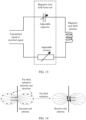
- FIG. 14 and FIG. 16 respectively show far field transmitting and receiving principles of an electric dipole antenna and a magnetic dipole antenna in a specific case.
- FIG. 14 is an example diagram of transmission and reception of an electric dipole antenna in far field communication according to an embodiment of this application.
- FIG. 18 is an example diagram of transmission and reception of a magnetic dipole antenna in far field communication according to an embodiment of this application. It can be learned from FIG. 17 and FIG.
- a transmit-end antenna has different transmit directions, and only far field transmission along a specific direction can be received by a receive-end antenna.
- the transmit-end antenna in FIG. 14 to FIG. 16 is a far field antenna at a transmit end, and that the receive-end antenna is a far field antenna at a receive end.
- FIG. 16 is a schematic diagram of an equivalent circuit of a transmission link for far field communication according to an embodiment of this application.
- (a) in FIG. 16 shows an equivalent circuit of a transmission link on which an electric dipole antenna is located
- (b) in FIG. 16 shows an equivalent circuit of a transmission link on which a magnetic dipole antenna is located.
- (a) shows an equivalent circuit of an electric far field
- (b) shows an equivalent circuit of a magnetic far field. It can be learned from FIG. 16 that, in the electric far field (that is, (a) in FIG.
- a resistor, a capacitor, and an inductor are connected in series at two ends of a front end (an example of a far field front end) of the electric dipole antenna.
- a resistor, a capacitor, and an inductor are connected in parallel at two ends of a front end (another example of the far field front end) of the magnetic dipole antenna.
- a transmit capability of the antenna is represented by transmit impedance, and a resonance frequency is determined by capacitance and inductance.
- the inductance and capacitance are adjustable. Therefore, the resonance frequency is also adjustable.
- a signal or energy may be sent from any two or three of an electric near field, a magnetic near field, and an electromagnetic far field simultaneously.
- a processing module at a transmit end divides a signal into three signals, and sends the three signals to a magnetic near field transmission link, an electric near field transmission link, and a far field transmission link respectively.
- signals transmitted on the transmission links are located in a same frequency band, or frequency bands of the signals overlap.
- Each of a magnetic near field transmission link, an electric near field transmission link, and a far field transmission link at a receive end receives three signals.
- the magnetic near field transmission link should receive only a magnetic near field signal
- the electric near field transmission link should receive only an electric near field signal
- the far field transmission link should receive only a far field signal.
- signals of the other two links are also received.
- the frequency bands are the same or overlap, there is potential interference. The following analyzes the interference.
- a receiving status of Te is checked.
- coupling strength of the electric near field signal mainly depends on capacitance between the transmit end and the receive end.
- strength of a received signal is mainly determined by an area that is of an electric near field antenna (or electrode) at the receive end and that is directly opposite to a transmit antenna.
- the electric near field antenna at the receive end is an electrode having a specific area
- the magnetic near field antenna is a loop antenna or a coil
- an area enclosed by the antenna is relatively large, but an area of an antenna body itself is relatively small.
- a conducting wire is relatively slim, and a far field antenna may use a relatively slim antenna body, so that an area can be reduced.
- the electric near field antenna at the receive end is a disc with a diameter of 2 centimeters, that is, the area of the electric near field antenna is ⁇ square centimeters;
- the magnetic near field antenna is a five-turn circular loop antenna with a diameter of 1 to 1.4 centimeters, and a spacing between the turns is 0.05 centimeter;
- the far field antenna is a dipole antenna, and a length of each side is 10 centimeters, a width is 0.05 centimeter, and a transmission frequency is 40 MHz.
- Capacitive coupling strength of the electric near field signal on the electric near field antenna approximately calculated according to an area relationship, is about 13 times that on the magnetic near field antenna and 3 times that on the far field antenna.
- the magnetic near field antenna is usually a closed loop
- an electric potential generated by the capacitive coupling cannot form an obvious electric potential difference at each position of the magnetic near field antenna, and cannot directly form an interference signal.
- Only weak induced electric potential differences at different positions of the antenna finally form an interference signal, which accounts for only a small proportion of coupling energy and depends on coupling differences at different positions of the antenna.
- Interference received on the far field antenna is also similar. Therefore, an interference signal generated by the electric near field is far weaker than a signal received by the electric near field antenna.
- the electric near field antenna also transmits a small quantity of signals.
- due to a size mismatch for example, because a size of the electric near field antenna is far smaller than that of the far field antenna in the foregoing example, a proportion of electric near field signals transmitted to the far field antenna is almost very small.
- Coupling strength of the magnetic near field signal depends on a common magnetic flux, that is, a mutual inductance coefficient.
- the electric near field antenna does not have a closed loop for feeding a received signal. Therefore, an induced (that is, a magnetic near field signal) received by the electric near field antenna is very weak.
- an open antenna or an antenna whose closed area is far less than that of the magnetic near field antenna is generally used.
- An open antenna refers to a far field antenna on which there is no path from one connection port to another connection port along an antenna body, as shown in (c) in FIG. 2 . Therefore, the received induced signal is also very weak. Therefore, Rem ⁇ Rm, and Rxm ⁇ Rm, where Rem and Rxm are magnetic near field signals that are received by the electric near field antenna and the far field antenna respectively from the magnetic near field antenna.
- an effective electrical size of the electric near field antenna or the magnetic near field antenna is smaller than that of the far field antenna at the receive end.
- sizes of the electric near field antenna and the magnetic near field antenna are 2 centimeters and 1.4 centimeters respectively, and a size of the far field antenna is 20 centimeters. Therefore, a received signal Rex on the electric near field antenna and a received signal Rmx on the magnetic near field antenna are far weaker than a received signal Rx on the far field antenna, that is, Rex ⁇ Rx, and Rmx ⁇ Rx.
- received signal-to-interference ratios signals-to-interference ratios for short
- received signal-to-interference ratios signals-to-interference ratios for short
- Rx, Re, and Rm are relatively close.
- a difference is controlled within a specific threshold. In this way, it can be ensured that each transmission link obtains a relatively high signal-to-interference ratio, so that the system has a relatively good signal or energy capacity.
- transmit signal power Tx, Te, and Tm may be adjusted based on an initial received signal power condition of each antenna, so that Rx, Re, and Rm are within a threshold range.
- the receive end may feed back measured power to the transmit end, and the transmit end adjusts the transmit signal power based on received signal power that is fed back.
- the foregoing steps may be performed by using a processing module of an antenna apparatus at the receive end and a processing module of an antenna apparatus at the transmit end.
- the transmit end may directly measure a local current to know received signal power, and adjust transmit signal power Tx, Te, and Tm accordingly.
- the foregoing steps may be performed by using the processing module of the antenna apparatus at the receive end and the processing module of the antenna apparatus at the transmit end.
- FIG. 7 is a schematic diagram of a circuit model for electric near field communication according to an embodiment of this application. As shown in FIG. 17 , signal transmission is implemented between a transmit end and a receive end through capacitive coupling.
- coupling capacitance is C
- receive load resistance is Rr
- a receive load current is Ir
- a transmit signal voltage is V
- a transmit signal current is I
- resistance from a positive electrode of the transmit end to the ground is Rt1
- resistance from a negative electrode of the transmit end to the ground is Rt2
- a current from the positive electrode of the transmit end to the ground is Ir1
- a current from the negative electrode of the transmit end to the ground is Ir2.
- Vr Ir*Rr
- It1*Rt1 Ir*(1/(j ⁇ C)+Rr)
- Ir It2-It1 where a signal frequency is ⁇ .
- the receive end does not provide a feedback at the beginning. Therefore, the transmit end may not know the load resistance Rr of the receive end.
- the receive end may alternatively feed back received energy initially, and the transmit end subsequently determines received power by directly measuring the local current.
- the load resistance of the receive end is a standard fixed value. Therefore, the transmit end can determine the received power by directly measuring the local current at the beginning.
- FIG. 18 is a schematic diagram of a circuit model for magnetic near field communication according to an embodiment of this application.
- capacitance, inductance, and resistance of a transmit end are Ct, Lt, and Rt respectively
- capacitance, inductance, and resistance of a receive end are Cr, Lr, and Rr respectively
- a signal voltage of the transmit end is V
- a change of mutual inductance M corresponds to a change of a communication distance, that is, if It increases, M decreases, that is, the distance increases, and energy coupled to the receive end decreases.
- the transmit end may not know load resistance Rr of the receive end at the beginning.
- the receive end may alternatively feed back received energy at the beginning, and the transmit end subsequently determines received power by directly measuring the local current.
- the load resistance of the receive end is a standard fixed value. Therefore, the transmit end can determine the received power by directly measuring the local current at the beginning.
- a method for adjusting transmit power may be: increasing power of a transmit signal transmission link corresponding to a transmission link with relatively low received power, or decreasing power of a transmit signal transmission link corresponding to a transmission link with relatively high received power. This is equivalent to enabling each transmission link to be maximized, so that overall transmission efficiency is improved as much as possible.
- the foregoing analysis is based on presence of three links (including corresponding transmit antennas and receive antennas): a far field link, an electric near field link, and a magnetic near field link. If there are only two of the links, for example, a far field link and an electric near field link, or a far field link and a magnetic near field link, or an electric near field link and a magnetic near field link, the method is similar, and is not described again for brevity.
- one or more links include a plurality of sub-links, for example, a plurality of electric near field transmission links, a plurality of magnetic near field transmission links, and a plurality of far field transmission links shown in FIG. 4 and FIG. 5 .
- a capacity is doubled by using a multiple-input multiple-output technology. In this case, transmit power that needs to be adjusted is total transmit power of the plurality of sub-links.
- the processing module of the transmit end may determine, based on differences between data rates and differences between transmit power of various links, whether to disable some links, to achieve better energy efficiency.
- the transmit power of the far field link is Px
- the data rate of the far field link is Dx
- the transmit power of the magnetic near field link is Pm
- the data rate of the magnetic near field link is Dm
- the transmit power of the far field link and the transmit power of the magnetic near field link obtained herein are Px' and Pm' respectively.
- the power of the far field link increases to Px.
- the power of the magnetic near field link decreases to [Pm'-(Px"-Px')].
- the corresponding data rate is Dm'
- the power of the far field link decreases to [Px'-(Pm"-Pm')].
- the corresponding data rate is Dx
- Values of D, D', and D" are compared, and a case with the highest data rate is selected.
- D' is the largest, the transmit power of the far field link is increased and the transmit power of the magnetic near field link is decreased; if D" is the largest, the transmit power of the far field link is decreased and the transmit power of the magnetic near field link is increased; or if D is the largest, no additional operation is required.
- D, D', and D" are compared. If D' is the largest, the transmit power of the far field link is increased, and the magnetic near field link is disabled. If D" is the largest, the far field link is disabled, and the transmit power of the magnetic near field link is increased. If D is the largest, no additional operation is required.
- a far field link, a magnetic near field link, and an electric near field link Transmit power and a data rate corresponding to each link are investigated.
- transmit power of one link is increased, and transmit power of another link is correspondingly decreased at the same time, and a corresponding data rate is calculated based on the transmit power, and the data rate is increased, such an operation is used; otherwise, such an operation is not used.
- the transmit power is decreased to 0 or a threshold (generally a power value corresponding to lowest transmit power specified for a transmitter), it means that the link is disabled.
- a method for calculating a data rate based on power is as follows: A difference between a demodulation threshold of a current data rate and a demodulation threshold of a changed data rate is a difference of a power change.
- a modulation mode changes from quadrature phase shift keying (quadrature phase shift keying, QPSK) to quadrature amplitude modulation (quadrature amplitude modulation, QAM). For example, if the demodulation threshold needs to be increased by 6 dB, the transmit power needs to be increased by 6 dB. If the power needs to be increased by 8 dB, the data rate is doubled.
- QPSK quadrature phase shift keying
- QAM quadrature amplitude modulation
- the transmit end may calculate received power based on the measured local current, when the local current is higher than a threshold, the transmit end determines that near field communication is not suitable, disables the local link, and enables another link, for example, enables the far field link and performs far field communication.
- the transmit end In far field communication, the transmit end generally learns received signal power depending on the feedback of the receive end. Therefore, if the received power of the receive end is higher than a threshold, the transmit end determines that near field communication can be used, and may enable the magnetic or electric near field communication link and disable the far field link.
- the transmit end divides a signal into a plurality of signals and transmits the signals on different types of transmission links. If there are at least two different signals, multiplexing is implemented by using different near field links or far and near field links. If the signals are the same, diversity is implemented by using different near field links or far and near field links. Multiplexing can increase a channel capacity, and diversity improves quality of a received signal.
- the transmit end may calculate the power of the receive end based on the feedback of the receive end or based on the current of the transmit end. It is assumed that transmit power consumption of the far field link, the electric near field link, and the magnetic near field link is Px, Pe, and Pm respectively, and that received power is Rx, Re, and Rm respectively.
- a detection method may be used.
- a link with lowest power efficiency is selected to reduce transmit power consumption of the link, and transmit power consumption of a link with highest power efficiency is increased.
- ⁇ x lowest efficiency
- transmit power consumption of the far field link is decreased by ⁇ x.
- ⁇ m transmit power consumption of the magnetic near field link is increased by ⁇ x.
- the power of the receive end is calculated based on the feedback of the receive end or the local current. Whether total received power increases is investigated.
- the transmit power consumption herein is different from the transmit power. Due to non-linearity of the amplifier and fixed consumption of components, the transmit power consumption is generally not in a linear relationship with the transmit power. When the power allocated to a link is lower than a threshold, transmission of the link may be disabled.
- the transmit power consumption may be understood as transmit energy.
- the foregoing mainly describes the antenna apparatus.
- the following describes a method for performing communication by using the foregoing antenna apparatus. Because some methods used when the antenna apparatus works are also described above as interludes, some content is omitted for brevity. For the omitted content, refer to the foregoing related content.
- FIG. 19 is a schematic flowchart of a communication method according to an embodiment of this application.
- FIG. 19 mainly describes a communication method for an antenna apparatus at a transmit end.
- the antenna apparatus at the transmit end may be any one of the foregoing antenna apparatuses. Therefore, any one of the foregoing antenna apparatuses at the transmit end may be used to perform steps in FIG. 19 .
- the following describes the steps in FIG. 19 .
- Step 1901 may be performed by using the foregoing processing module of the antenna apparatus at the transmit end.
- the to-be-transmitted signal may be understood as a signal that has been processed.
- the processing module may be used to perform processing such as encoding and modulation to obtain the to-be-transmitted signal, or perform specific processing to obtain to-be-transmitted energy.
- Each transmission link includes a front end and an antenna, that is, an antenna and a matching circuit thereof form a transmission path.
- the plurality of transmission links may include at least one electric near field transmission link and at least one magnetic near field transmission link.
- a same signal or different signals may be simultaneously sent from an electric near field and an electromagnetic field. Therefore, a signal or energy transmission capacity is increased, and transmission efficiency can be improved.
- a signal or energy may be simultaneously sent from the electric near field transmission link and the magnetic near field transmission link at a same frequency (that is, a same transmit frequency).
- transmit power of the to-be-transmitted signal on the plurality of transmission links may be allocated.
- the allocation of transmit power can improve overall transmission efficiency as much as possible. For example, in a scenario suitable for far field communication, less power may be allocated to an electric near field transmission link and a magnetic near field transmission link, and more power is allocated to a far field transmission link. For another example, in a scenario suitable for electric near field communication, more power may be allocated to an electric near field transmission link, and less power is allocated to other transmission links.
- zero power may be allocated to one or more transmission links, that is, no transmit power is allocated to some transmission links. This is equivalent to disabling these transmission links.
- the plurality of transmission links include an electric near field transmission link and a magnetic near field transmission link. Allocating zero power to the electric near field transmission link is equivalent to using only the magnetic near field transmission link to transmit a signal or energy. Allocating power only to the electric near field transmission link or allocating power only to the magnetic near field transmission link is equivalent to implementing switching between the electric near field transmission link and the magnetic near field transmission link.
- the plurality of transmission links include at least one electric near field transmission link, at least one magnetic near field transmission link, and at least one far field transmission link, during power allocation, only one or two of the transmission links may be selected, and this is equivalent to implementing automatic switching between the transmission links. It should be understood that, in this embodiment of this application, as power is allocated, the switching is performed and changes continuously, and is not hard switching. Therefore, the switching is more flexible and applicable.
- the transmit power may be further adjusted based on received power, so that when an antenna apparatus at a receive end receives the to-be-transmitted signal, a difference of received power on a plurality of transmission links of the antenna apparatus at the receive end is within a preset range.
- the transmit power of the transmit end is adjusted, so that the difference of the received power on the transmission links of the receive end is relatively small.
- the adjustment of transmit power can improve overall transmission efficiency as much as possible. For example, in a scenario suitable for far field communication, power allocated to the electric near field transmission link and the magnetic near field transmission link may be decreased, or even no power is allocated to the two transmission links, and power allocated to the far field transmission link is increased. For another example, in a scenario suitable for electric near field communication, power allocated to the electric near field transmission link may be increased. Which scenarios are suitable may be learned based on the receiving status. Therefore, adjusting power allocation based on the receiving status can implement switching between the transmission links according to different scenarios, and the switching is more accurate and flexible than hard switching.
- received power on an electric near field transmission link of the antenna apparatus at the receive end may be obtained based on a current on the electric near field transmission link of the antenna apparatus at the transmit end.
- a current may be measured on the electric near field transmission link of the transmit end, so that the received power on the electric near field transmission link of the receive end is calculated.
- the receive end does not provide a feedback at the beginning. Therefore, the transmit end may not know load resistance Rr of the receive end.
- the receive end may alternatively feed back received energy at the beginning, and the transmit end subsequently determines the received power by directly measuring the local current.
- the load resistance of the receive end is a standard fixed value. Therefore, the transmit end can determine the received power by directly measuring the local current at the beginning.
- the plurality of transmission links transmit the to-be-transmitted signal.
- the plurality of transmission links may simultaneously transmit the to-be-transmitted signal at a same transmit frequency.
- the antenna apparatus in this embodiment of this application is further applicable to energy transmission. Therefore, the foregoing communication method may further perform the following operations: generating to-be-transmitted energy, and transmitting the to-be-transmitted energy to the plurality of transmission links; transmitting, by the plurality of transmission links, the to-be-transmitted energy; and adjusting energy allocation of the to-be-transmitted energy of the antenna apparatus at the transmit end on the plurality of transmission links based on a status of receiving the to-be-transmitted energy by the antenna apparatus at the receive end.
- the transmit end may calculate the power of the receive end based on the feedback of the receive end or based on the current of the transmit end. It is assumed that transmit power consumption of the far field link, the electric near field link, and the magnetic near field link is Px, Pe, and Pm respectively, and that received power is Rx, Re, and Rm respectively. A detection method may be used. Usually, a link with lowest power efficiency is selected to reduce transmit power consumption of the link, and transmit power consumption of a link with highest power efficiency is increased.
- ⁇ x lowest efficiency
- transmit power consumption of the far field link is decreased by ⁇ x.
- ⁇ m highest efficiency
- transmit power consumption of the magnetic near field link is increased by ⁇ x.
- the power of the receive end is calculated based on the feedback of the receive end or the local current. Whether total received power increases is investigated. If the total received power increases, power allocation is updated; otherwise, the original power allocation is maintained. Further, if an increase is greater than a threshold, the foregoing process is continued; otherwise, only one power update is performed.
- the transmit power consumption herein is different from the transmit power Due to non-linearity of an amplifier and fixed consumption of components, the transmit power consumption is generally not in a linear relationship with the transmit power.
- the power allocated to a link is lower than a threshold, transmission of the link may be disabled.
- FIG. 20 is a schematic flowchart of a communication method according to an embodiment of this application.
- FIG. 20 mainly describes a communication method for an antenna apparatus at a receive end.
- the antenna apparatus at the receive end may be any one of the foregoing antenna apparatuses. Therefore, any one of the foregoing antenna apparatuses at the receive end may be used to perform steps in FIG. 20 .
- the following describes the steps in FIG. 20 .
- a plurality of transmission links receive a signal or energy.
- a processing module may be used to perform combination processing on received signals or energy, and may further perform processing such as decoding, demodulation, and descrambling.
- the received power of the signal or energy on the plurality of transmission links may be further fed back to the antenna apparatus at the transmit end, so that the antenna apparatus at the transmit end can adjust power or energy allocation of the antenna apparatus based on the feedback.
- the disclosed system, apparatus, and method may be implemented in other manners.
- the described apparatus embodiments are merely examples.
- the division of units is merely logical function division and may be other division in actual implementation.
- a plurality of units or components may be combined or integrated into another system, or some features may be ignored or may not be performed.
- the displayed or discussed mutual couplings or direct couplings or communications connections may be implemented by using some interfaces.
- the indirect couplings or communications connections between apparatuses or units may be implemented in electrical, mechanical, or other forms.
- the units described as separate parts may or may not be physically separate, and parts displayed as units may or may not be physical units, may be located in one position, or may be distributed on a plurality of network units. Some or all of the units may be selected based on an actual requirement, to achieve the objectives of the solutions in the embodiments.
- the functions When the functions are implemented in a form of a software functional unit and sold or used as a separate product, the functions may be stored in a computer-readable storage medium. Based on such an understanding, the technical solutions of this application essentially or parts contributing to the prior art or some of the technical solutions may be embodied in a form of a software product.
- the computer software product is stored in a storage medium, and includes several instructions for instructing a computer device (which may be a personal computer, a server, a network device, or the like) to perform all or some of the steps of the methods described in the embodiments of this application.
- the foregoing storage medium includes any medium that can store program code, such as a USB flash drive, a removable hard disk, a read-only memory (read-only memory, ROM), a random access memory (random access memory, RAM), a magnetic disk, or an optical disc.
- program code such as a USB flash drive, a removable hard disk, a read-only memory (read-only memory, ROM), a random access memory (random access memory, RAM), a magnetic disk, or an optical disc.
Landscapes
- Engineering & Computer Science (AREA)
- Computer Networks & Wireless Communication (AREA)
- Signal Processing (AREA)
- Near-Field Transmission Systems (AREA)
Applications Claiming Priority (1)
| Application Number | Priority Date | Filing Date | Title |
|---|---|---|---|
| PCT/CN2021/078120 WO2022178823A1 (zh) | 2021-02-26 | 2021-02-26 | 天线装置和通信方法 |
Publications (2)
| Publication Number | Publication Date |
|---|---|
| EP4287403A1 true EP4287403A1 (de) | 2023-12-06 |
| EP4287403A4 EP4287403A4 (de) | 2024-04-03 |
Family
ID=83047593
Family Applications (1)
| Application Number | Title | Priority Date | Filing Date |
|---|---|---|---|
| EP21927260.6A Pending EP4287403A4 (de) | 2021-02-26 | 2021-02-26 | Antennenvorrichtung und kommunikationsverfahren |
Country Status (4)
| Country | Link |
|---|---|
| US (1) | US20230403047A1 (de) |
| EP (1) | EP4287403A4 (de) |
| CN (1) | CN116745993A (de) |
| WO (1) | WO2022178823A1 (de) |
Families Citing this family (1)
| Publication number | Priority date | Publication date | Assignee | Title |
|---|---|---|---|---|
| CN119093987B (zh) * | 2024-08-22 | 2026-02-17 | 华中科技大学 | 一种低频通信抗干扰方法及系统 |
Family Cites Families (17)
| Publication number | Priority date | Publication date | Assignee | Title |
|---|---|---|---|---|
| US7576657B2 (en) * | 2006-03-22 | 2009-08-18 | Symbol Technologies, Inc. | Single frequency low power RFID device |
| EP1998468A3 (de) * | 2007-05-31 | 2012-06-06 | Broadcom Corporation | RFID-Lesegerät-Architektur mit mehreren Betriebsarten |
| US8629650B2 (en) * | 2008-05-13 | 2014-01-14 | Qualcomm Incorporated | Wireless power transfer using multiple transmit antennas |
| US8682261B2 (en) * | 2009-02-13 | 2014-03-25 | Qualcomm Incorporated | Antenna sharing for wirelessly powered devices |
| KR101339690B1 (ko) * | 2011-12-30 | 2013-12-11 | 한국과학기술원 | 근거리 통신 및 무선 전력 전송 시스템 및 방법 |
| US9325080B2 (en) * | 2014-03-03 | 2016-04-26 | Apple Inc. | Electronic device with shared antenna structures and balun |
| US10009069B2 (en) * | 2014-05-05 | 2018-06-26 | Nxp B.V. | Wireless power delivery and data link |
| US9756578B2 (en) * | 2015-04-10 | 2017-09-05 | Qualcomm Incorporated | Systems and methods for transmit power control |
| US9819097B2 (en) * | 2015-08-26 | 2017-11-14 | Nxp B.V. | Antenna system |
| CN105305068B (zh) * | 2015-09-23 | 2019-02-05 | 联想(北京)有限公司 | 一种组合天线以及一种电子设备 |
| US10320086B2 (en) * | 2016-05-04 | 2019-06-11 | Nxp B.V. | Near-field electromagnetic induction (NFEMI) antenna |
| US10200092B1 (en) * | 2017-09-28 | 2019-02-05 | Apple Inc. | Electronic device having multiple antennas with shared structures for near-field communications and non-near-field communications |
| CN108964722A (zh) * | 2018-06-21 | 2018-12-07 | 成都凯力科技有限公司 | 无线传输方法 |
| US10566690B1 (en) * | 2018-10-09 | 2020-02-18 | Nxp Usa, Inc. | Near-field induction voltage boost circuit |
| US10917138B2 (en) * | 2019-01-29 | 2021-02-09 | Nxp B.V. | Near-field communications device |
| US10819024B1 (en) * | 2019-04-10 | 2020-10-27 | Nxp B.V. | Combination near-field and far-field antenna |
| CN111934725B (zh) * | 2020-09-16 | 2021-03-19 | 深圳市汇顶科技股份有限公司 | 近场通信装置和电子设备 |
-
2021
- 2021-02-26 EP EP21927260.6A patent/EP4287403A4/de active Pending
- 2021-02-26 CN CN202180087748.8A patent/CN116745993A/zh active Pending
- 2021-02-26 WO PCT/CN2021/078120 patent/WO2022178823A1/zh not_active Ceased
-
2023
- 2023-08-25 US US18/238,032 patent/US20230403047A1/en active Pending
Also Published As
| Publication number | Publication date |
|---|---|
| US20230403047A1 (en) | 2023-12-14 |
| CN116745993A (zh) | 2023-09-12 |
| EP4287403A4 (de) | 2024-04-03 |
| WO2022178823A1 (zh) | 2022-09-01 |
Similar Documents
| Publication | Publication Date | Title |
|---|---|---|
| CN112751212B (zh) | 天线系统及电子设备 | |
| CN112821031B (zh) | 电子设备 | |
| EP2991185B1 (de) | Drahtlose stromübertragungsvorrichtung und verfahren dafür | |
| US8466791B2 (en) | Communication device, antenna device, and communication system | |
| EP3767742B1 (de) | Antennenvorrichtung und mobiles endgerät | |
| EP2278684A2 (de) | Kontaktlose stromversorgende Kommunikationsvorrichtung, kontaktlose stromempfangende Kommunikationsvorrichtung, stromversorgendes Kommunikationssteuerungsverfahren und stromempfangendes Kommunikationssteuerungsverfahren | |
| US11095029B2 (en) | Antenna device | |
| US9954275B2 (en) | Multiple-input multiple-output antenna, system and mobile terminal | |
| EP3624357A1 (de) | Verhältnissteuerung von elektromagnetischer nahfeldinduktion (nfemi) | |
| JP5094630B2 (ja) | Icタグ | |
| EP3806238B1 (de) | Mobiles endgerät | |
| US20130307344A1 (en) | Resonance coupling wireless power transfer receiver and transmitter | |
| US9225381B2 (en) | Tunable quality factor | |
| US20230403047A1 (en) | Antenna apparatus and communication method | |
| CN108258407B (zh) | 一种天线及无线通信电子设备 | |
| CN202977729U (zh) | 天线调谐装置及移动终端 | |
| KR20140076993A (ko) | 무선 전력 장치 | |
| CN205490708U (zh) | 天线系统及其移动终端 | |
| US11699056B2 (en) | RFID inlay | |
| Valkonen et al. | Dual-feed, single-CCE antenna facilitating inter-band carrier aggregation in LTE-A handsets | |
| CN103682565A (zh) | 天线和用于形成天线的方法 | |
| CN108964722A (zh) | 无线传输方法 | |
| US10305169B2 (en) | Antenna apparatus and terminal | |
| CN215869802U (zh) | 天线模组及电子设备 | |
| CN211152213U (zh) | 磁通信被动接口以及nfc通信设备 |
Legal Events
| Date | Code | Title | Description |
|---|---|---|---|
| STAA | Information on the status of an ep patent application or granted ep patent |
Free format text: STATUS: THE INTERNATIONAL PUBLICATION HAS BEEN MADE |
|
| PUAI | Public reference made under article 153(3) epc to a published international application that has entered the european phase |
Free format text: ORIGINAL CODE: 0009012 |
|
| STAA | Information on the status of an ep patent application or granted ep patent |
Free format text: STATUS: REQUEST FOR EXAMINATION WAS MADE |
|
| 17P | Request for examination filed |
Effective date: 20230831 |
|
| AK | Designated contracting states |
Kind code of ref document: A1 Designated state(s): AL AT BE BG CH CY CZ DE DK EE ES FI FR GB GR HR HU IE IS IT LI LT LU LV MC MK MT NL NO PL PT RO RS SE SI SK SM TR |
|
| A4 | Supplementary search report drawn up and despatched |
Effective date: 20240304 |
|
| RIC1 | Information provided on ipc code assigned before grant |
Ipc: H04W 52/38 20090101ALI20240227BHEP Ipc: H04B 5/72 20240101ALI20240227BHEP Ipc: H04B 5/43 20240101ALI20240227BHEP Ipc: H04B 5/79 20240101ALI20240227BHEP Ipc: H01Q 1/50 20060101ALI20240227BHEP Ipc: H01Q 7/08 20060101AFI20240227BHEP |
|
| DAV | Request for validation of the european patent (deleted) | ||
| DAX | Request for extension of the european patent (deleted) |