EP4287701A2 - Procédé et appareil de commutation - Google Patents
Procédé et appareil de commutation Download PDFInfo
- Publication number
- EP4287701A2 EP4287701A2 EP23197249.8A EP23197249A EP4287701A2 EP 4287701 A2 EP4287701 A2 EP 4287701A2 EP 23197249 A EP23197249 A EP 23197249A EP 4287701 A2 EP4287701 A2 EP 4287701A2
- Authority
- EP
- European Patent Office
- Prior art keywords
- drb
- base station
- configuration information
- qos
- information
- Prior art date
- Legal status (The legal status is an assumption and is not a legal conclusion. Google has not performed a legal analysis and makes no representation as to the accuracy of the status listed.)
- Pending
Links
Images




Classifications
-
- H—ELECTRICITY
- H04—ELECTRIC COMMUNICATION TECHNIQUE
- H04W—WIRELESS COMMUNICATION NETWORKS
- H04W28/00—Network traffic management; Network resource management
- H04W28/02—Traffic management, e.g. flow control or congestion control
- H04W28/0268—Traffic management, e.g. flow control or congestion control using specific QoS parameters for wireless networks, e.g. QoS class identifier [QCI] or guaranteed bit rate [GBR]
-
- H—ELECTRICITY
- H04—ELECTRIC COMMUNICATION TECHNIQUE
- H04W—WIRELESS COMMUNICATION NETWORKS
- H04W36/00—Hand-off or reselection arrangements
- H04W36/0005—Control or signalling for completing the hand-off
- H04W36/0011—Control or signalling for completing the hand-off for data sessions of end-to-end connection
- H04W36/0033—Control or signalling for completing the hand-off for data sessions of end-to-end connection with transfer of context information
- H04W36/0044—Control or signalling for completing the hand-off for data sessions of end-to-end connection with transfer of context information of quality context information
-
- H—ELECTRICITY
- H04—ELECTRIC COMMUNICATION TECHNIQUE
- H04W—WIRELESS COMMUNICATION NETWORKS
- H04W28/00—Network traffic management; Network resource management
- H04W28/16—Central resource management; Negotiation of resources or communication parameters, e.g. negotiating bandwidth or QoS [Quality of Service]
- H04W28/24—Negotiating SLA [Service Level Agreement]; Negotiating QoS [Quality of Service]
-
- H—ELECTRICITY
- H04—ELECTRIC COMMUNICATION TECHNIQUE
- H04W—WIRELESS COMMUNICATION NETWORKS
- H04W36/00—Hand-off or reselection arrangements
-
- H—ELECTRICITY
- H04—ELECTRIC COMMUNICATION TECHNIQUE
- H04W—WIRELESS COMMUNICATION NETWORKS
- H04W36/00—Hand-off or reselection arrangements
- H04W36/0005—Control or signalling for completing the hand-off
- H04W36/0011—Control or signalling for completing the hand-off for data sessions of end-to-end connection
- H04W36/0027—Control or signalling for completing the hand-off for data sessions of end-to-end connection for a plurality of data sessions of end-to-end connections, e.g. multi-call or multi-bearer end-to-end data connections
-
- H—ELECTRICITY
- H04—ELECTRIC COMMUNICATION TECHNIQUE
- H04W—WIRELESS COMMUNICATION NETWORKS
- H04W36/00—Hand-off or reselection arrangements
- H04W36/0005—Control or signalling for completing the hand-off
- H04W36/0055—Transmission or use of information for re-establishing the radio link
- H04W36/0064—Transmission or use of information for re-establishing the radio link of control information between different access points
-
- H—ELECTRICITY
- H04—ELECTRIC COMMUNICATION TECHNIQUE
- H04W—WIRELESS COMMUNICATION NETWORKS
- H04W36/00—Hand-off or reselection arrangements
- H04W36/0005—Control or signalling for completing the hand-off
- H04W36/0055—Transmission or use of information for re-establishing the radio link
- H04W36/0072—Transmission or use of information for re-establishing the radio link of resource information of target access point
-
- H—ELECTRICITY
- H04—ELECTRIC COMMUNICATION TECHNIQUE
- H04W—WIRELESS COMMUNICATION NETWORKS
- H04W36/00—Hand-off or reselection arrangements
- H04W36/08—Reselecting an access point
-
- H—ELECTRICITY
- H04—ELECTRIC COMMUNICATION TECHNIQUE
- H04W—WIRELESS COMMUNICATION NETWORKS
- H04W36/00—Hand-off or reselection arrangements
- H04W36/24—Reselection being triggered by specific parameters
- H04W36/26—Reselection being triggered by specific parameters by agreed or negotiated communication parameters
-
- H—ELECTRICITY
- H04—ELECTRIC COMMUNICATION TECHNIQUE
- H04W—WIRELESS COMMUNICATION NETWORKS
- H04W68/00—User notification, e.g. alerting and paging, for incoming communication, change of service or the like
- H04W68/005—Transmission of information for alerting of incoming communication
-
- H—ELECTRICITY
- H04—ELECTRIC COMMUNICATION TECHNIQUE
- H04W—WIRELESS COMMUNICATION NETWORKS
- H04W76/00—Connection management
- H04W76/20—Manipulation of established connections
- H04W76/27—Transitions between radio resource control [RRC] states
-
- H—ELECTRICITY
- H04—ELECTRIC COMMUNICATION TECHNIQUE
- H04W—WIRELESS COMMUNICATION NETWORKS
- H04W80/00—Wireless network protocols or protocol adaptations to wireless operation
- H04W80/02—Data link layer protocols
-
- H—ELECTRICITY
- H04—ELECTRIC COMMUNICATION TECHNIQUE
- H04W—WIRELESS COMMUNICATION NETWORKS
- H04W80/00—Wireless network protocols or protocol adaptations to wireless operation
- H04W80/08—Upper layer protocols
Definitions
- FIG. 1 is a structural diagram of a 4G system.
- 4G 4th Generation
- LTE Long Term Evolution
- data flows with the same Quality of Service (QoS) requirement are aggregated into a bearer.
- An access network (AN) and a core network (CN) process the QoS according to the bearer.
- the access network includes an evolved Node B (eNB) and a user equipment (UE). If one network side bearer on an S1 interface between the eNB and the core network exists, one radio bearer on an air interface between the eNB and the UE correspondingly exists. That is, the network side bearer and the radio bearer are in one-to-one correspondence.
- eNB evolved Node B
- UE user equipment
- a QoS parameter includes: a QoS class identifier (QCI) and an allocation and retention priority (ARP).
- QCI includes a bearer type (a guaranteed bit rate (GBR) or a non-GBR), a priority, a packet delay budget and a packet error Rate.
- the APR is configured to indicate a priority of the bearer corresponding to deleting or retaining when an overload occurs.
- the QoS parameter further includes: an aggregate maximum bit rate (AMBR).
- the AMBR includes: aggregate maximum bit rates of all non-GBR bearers of the UE (UE-AMBR) and an aggregate maximum bit rate of a non-GBR bearer corresponding to an access point name (APN) (APN-AMBR).
- the QoS parameter further includes: a maximum bit rate (MBR) and a GBR.
- MBR maximum bit rate
- a policy and charging rule function (PCRF) in the core network ensures that the UE does not have two bearers of the same QoS in a packet data network (PDN) link.
- PDN packet data network
- FIG. 2 is a structural diagram of a 5th Generation (5G) system using the 5G mobile communication technology.
- 5G 5th Generation
- the 5G mobile communication system may have an improving demand for 1000 times network throughput capacity, 100 times device connections and one tenth lower latency.
- the 5G system requires a new and better QoS mechanism.
- the 5G system may adopt a unified structure to support an enhanced mobile broadband (eMBB), massive machine type communication (mMTC), ultra reliable and low latency communication (URLLC) and other services.
- eMBB enhanced mobile broadband
- mMTC massive machine type communication
- URLLC ultra reliable and low latency communication
- the core network, the base station and the UE may be greatly evolved.
- a base station for the transition from the 4G mobile communication technology to the 5G mobile communication technology may exist.
- An air interface of this type of base station is similar to an air interface of the base station (i.e., eNB) in the 4G system, and this type of base station may be successfully connected to a 5G core network via its air interface.
- eNB evolved eNB.
- a direct interface may also exist between 5G base stations in the 5G system, which is referred to as an Xn interface.
- the Xn interface may also exist between evolved eNBs or between the evolved eNB and the 5G base station.
- an interface between the 5G base station and the 5G core network in the 5G system is referred to as an NG interface.
- the NG interface may also exist between the evolved eNB and the 5G core network.
- a handover method and apparatus provided by the present disclosure may solve the problem that the QoS mechanism adopted by a core network and the QoS mechanism adopted by an access network are different when the base station is being handed over.
- a handover method includes:
- the flow QoS information item includes: identifier information for indicating the flow quality of service information item and a quality of service (Qos) rule.
- the identifier information includes a flow identifier or a quality of service identifier (QoS ID).
- the QoS rule includes at least one of the following: a packet delay budget (PDB), a packet error rate (PER), a priority, a guaranteed flow bit rate, a maximum flow bit rate, an allocation and retention priority, a per UE maximum bit rate, admission control, a flow priority level (FPL), a packet priority instruction (PPI), a packet discard priority indicator (PDPI), a quality of experience (QoE) level, and a reflective QoS indication.
- PDB packet delay budget
- PER packet error rate
- a priority a guaranteed flow bit rate
- a maximum flow bit rate an allocation and retention priority
- a per UE maximum bit rate admission control
- FPL flow priority level
- PPI packet priority instruction
- PDPI packet discard priority indicator
- QoE quality of experience
- each DRB information item includes: a DRB identifier (DRB ID); and the each DRB information item further includes: the flow ID associated with the DRB corresponding to the DRB ID or the QoS ID associated with the DRB corresponding to the DRB ID, and second DRB configuration information configured by the source base station for the DRB.
- the second DRB configuration information includes a packet data convergence protocol (PDCP), a radio link control (RLC) and a configuration parameter of a logical channel, which are configured by the source base station for the DRB.
- PDCP packet data convergence protocol
- RLC radio link control
- the method when the first DRB configuration information received by the source base station includes a flow ID or QoS ID that is not associated with any DRB in the one or more DRB information items, after the source base station transmits the RRC connection reconfiguration message to the UE, the method further includes: transmitting the flow ID or QoS ID that is not associated with any DRB in the one or more DRB information items by the source base station to a core network.
- a handover method includes:
- the generating first DRB configuration information by the target base station for the UE according to the handover request message includes:
- each DRB configuration information in the DRB addition modification list includes a first DRB ID and one or more of the following: one or more flow IDs or quality of service identifiers (QoS IDs) associated with a first DRB corresponding to the first DRB ID, packet data convergence protocol (PDCP) configuration information, radio link control (RLC) configuration information and logical channel configuration information.
- QoS IDs quality of service identifiers
- PDCP packet data convergence protocol
- RLC radio link control
- the one or more flow IDs or QoS IDs associated with the first DRB corresponding to the first DRB ID includes: one or more flow IDs or QoS IDs with which the first DRB is re-associated after the target base station changes an association relationship between the first DRB and the one or more flow IDs or QoS IDs.
- a handover method includes:
- the DRB configuration information includes: a DRB addition modification list and a DRB release list.
- Each tuple in the DRB addition modification list comprises a first DRB identifier and one or more of one or more flow IDs or quality of service identifiers (QoS IDs) associated with a first DRB corresponding to the first DRB identifier, packet data convergence protocol (PDCP) configuration information, radio link control (RLC) configuration information and logical channel configuration information, where the first DRB is a DRB in the one or more DRB information items which the target base station agrees to establish.
- QoS IDs quality of service identifiers
- Each tuple in the DRB release list comprises a second DRB ID, where a second DRB corresponding to the second DRB ID is a DRB in the one or more DRB information items which the target base station does not agree to establish.
- the configuring radio resources on the first DRB includes one or more of the following:
- a handover apparatus which is applied to a source base station, includes: a first transmission module, a reception module and a second transmission module.
- the first transmission module is configured to transmit a handover request message to a target base station when a user equipment (UE) is being handed over from the source base station to the target base station.
- the handover request message carries one or more DRB information items configured by the source base station for the UE and one or more flow QoS information items configured by a core network side for the UE.
- the reception module is configured to receive a handover request acknowledgement message transmitted by the target base station.
- the handover request acknowledgement message carries first DRB configuration information generated by the target base station for the UE according to the handover request message.
- the second transmission module is configured to transmit a radio resource control (RRC) connection reconfiguration message carrying the first DRB configuration information to the UE.
- RRC radio resource control
- the first DRB configuration information is used for configuring radio resources by the UE.
- the flow quality of service information item includes: identifier information for indicating the flow quality of service information item and a quality of service rule, where the identifier information includes a flow identifier or a quality of service identifier (QoS ID).
- the reception module is configured to receive a handover request message transmitted by a source base station when a UE is being handed over from the source base station to the target base station.
- the handover request message carries one or more DRB information items configured by the source base station for the UE and one or more flow QoS information items configured by a core network side for the UE.
- the generation module is configured to generate first DRB configuration information for the UE according to the handover request message.
- the transmission module is configured to transmit a handover request acknowledgement message carrying the first DRB configuration information to the source base station.
- the configuration unit is configured to put DRB configuration information corresponding to a first DRB in the one or more DRB information items which the target base station agrees to establish into a DRB addition modification list, and put a DRB identifier corresponding to a second DRB in the one or more DRB information items which the target base station does not agree to establish into a DRB release list.
- a handover apparatus which is applied to a user equipment (UE), includes: a reception module and a configuration module.
- the configuration module is configured to configure radio resources according to the DRB configuration information in the RRC connection reconfiguration message.
- Each tuple in the DRB addition modification includes a first DRB identifier and one or more of one or more flow IDs or quality of service identifiers (QoS IDs) associated with a first DRB corresponding to the first DRB identifier, packet data convergence protocol (PDCP) configuration information, radio link control (RLC) configuration information and logical channel configuration information, where the first DRB is a DRB in the one or more DRB information items which the target base station agrees to establish.
- QoS IDs quality of service identifiers
- a computer-readable storage medium stores computer-executable instructions for executing any method described above.
- a source base station includes:
- the memory stores instructions which may be executed by the at least one processor, and the at least one processor executes the instructions to execute the above method executed by the target base station.
- a source base station transmits a handover request message to a target base station when a user equipment (UE) is being handed over from the source base station to the target base station, where the handover request message carries one or more data radio bearer (DRB) information items configured by the source base station for the UE and one or more flow quality of service (Qos) information items configured by a core network side for the UE.
- DRB data radio bearer
- Qos flow quality of service
- the source base station receives a handover request acknowledgement message transmitted by the target base station.
- the handover request acknowledgement message carries first DRB configuration information generated by the target base station for the UE according to the handover request message.
- the source base station transmits a radio resource control (RRC) connection reconfiguration message carrying the first DRB configuration information to the UE, where the first DRB configuration information is used for being configured radio resources by the UE.
- RRC radio resource control
- the flow QoS information item includes: identifier information for indicating the flow QoS information item and a QoS rule, where the identifier information includes a flow identifier or a QoS ID.
- the QoS rule includes at least one of the following: a packet delay budget (PDB), a packet error rate (PER), a priority, a guaranteed flow bit rate, a maximum flow bit rate, an allocation and retention priority (ARP), a per UE maximum bit rate, admission control, a flow priority level (FPL), a packet priority instruction (PPI), a packet discard priority indicator (PDPI), a quality of experience (QoE) level (QoS Level), and a reflective QoS indication.
- PDB packet delay budget
- PER packet error rate
- ARP allocation and retention priority
- FPL flow priority level
- PPI packet priority instruction
- PDPI packet discard priority indicator
- QoE quality of experience
- QoS Level a reflective QoS indication.
- the reflective QoS indication is used for indicating that uplink flow QoS information is determined according to downlink flow QoS information.
- the QoS rule may not include the uplink flow QoS information.
- each DRB information item includes: a DRB ID.
- the DRB information item further includes: the flow ID associated with a DRB corresponding to the DRB ID or the QoS ID associated with the DRB corresponding to the DRB ID, and second DRB configuration information configured by the source base station for the DRB.
- the second DRB configuration information includes: a packet data convergence protocol (PDCP), radio link control (RLC) and a configuration parameter of a logical channel, which are configured by the source base station for the DRB.
- PDCP packet data convergence protocol
- RLC radio link control
- the method further includes: transmitting the flow ID or QoS ID that is not associated with any of all DRBs corresponding to all DRBs in all DRB information items by the source base station to a core network.
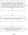
- FIG. 4 is a flowchart of a handover method according to an embodiment of the present disclosure. As shown in FIG. 4 , the method includes steps described below.
- step 402 when a user equipment (UE) is being handed over from a source base station to a target base station, the target base station receives a handover request message transmitted by the source base station.
- the handover request message carries one or more DRB information items configured by the source base station for the UE and one or more flow QoS information items configured by a core network side for the UE.
- step 404 the target base station generates first DRB configuration information for the UE according to the handover request message.
- step 406 the target base station transmits a handover request acknowledgement message carrying the first DRB configuration information to the source base station.
- the process of generating first DRB configuration information by the target base station for the UE according to the handover request message includes:
- each DRB configuration information in the DRB addition modification list includes a first DRB ID and one or more of the following: one or more flow IDs or QoS IDs associated with a DRB corresponding to the first DRB ID, packet data convergence protocol (PDCP) configuration information, radio link control (RLC) configuration information and logical channel configuration information.
- PDCP packet data convergence protocol
- RLC radio link control
- the method further includes: transmitting the flow ID or QoS ID that is not associated with any DRB in all DRB information items by the source base station to a core network.
- step 502 when a user equipment (UE) is being handed over from a source base station to a target base station, the UE receives a radio resource control (RRC) connection reconfiguration message carrying DRB configuration information transmitted by the source base station.
- the DRB configuration information is generated by the target base station for the UE according to a handover request message, and the handover request message is transmitted by the source base station to the target base station and carries one or more DRB information items configured by the source base station for the UE and one or more flow QoS information items configured by a core network side for the UE.
- RRC radio resource control
- step 504 the UE configures radio resources according to the DRB configuration information in the RRC connection reconfiguration message.
- the DRB configuration information includes: a DRB addition modification list and a DRB release list.
- Each tuple in the DRB addition modification list includes a first DRB ID and one or more of the following: one or more flow IDs or QoS IDs associated with a first DRB corresponding to the first DRB ID, PDCP configuration information, RLC configuration information and logical channel configuration information.
- the first DRB is a DRB in the DRB information items which the target base station agrees to establish.
- Each tuple in the DRB release list includes a second DRB ID, and the second DRB corresponding to the second DRB ID is a DRB in the DRB information items which the target base station does not agree to establish.
- the process of the UE configuring radio resources according to the DRB configuration information in the RRC connection reconfiguration message includes: configuring, by the UE, radio resources for the first DRB according to each tuple information in the DRB addition modification list, and releasing radio resources of the second DRB corresponding to the second DRB ID according to the second DRB ID in the each tuple information in the DRB release list.
- the configuring radio resources for the first DRB includes one or more of the following:
- the method in embodiments described above may be implemented by software plus a general-purpose hardware platform, or may be implemented by hardware.
- the solution provided by the present disclosure may be embodied in the form of a software product.
- the computer software product is stored in a non-transient storage medium (such as a read-only memory (ROM), a random-access memory (RAM), a magnetic disk or an optical disk) and the computer software product includes one or more instructions for enabling a terminal device (which may be a mobile phone, a computer, a server, a network device or the like) to execute the method described in the embodiments of the present disclosure.
- the computer software product may be stored in a transient storage medium.
- module may be at least one of software and hardware capable of implementing preset functions.
- FIG. 6 is a block diagram of a handover apparatus according to an embodiment of the present disclosure.
- the apparatus may be applied in a source base station.
- the apparatus includes: a first transmission module 60, a reception module 62 and a second transmission module 64.
- the reception module 62 is configured to receive a handover request acknowledgement message transmitted by the target base station.
- the handover request acknowledgement message carries first DRB configuration information generated by the target base station for the UE according to the handover request message.
- the second transmission module 64 is configured to transmit a radio resource control (RRC) connection reconfiguration message carrying the first DRB configuration information to the UE, where the first DRB configuration information is used by the UE for configuring radio resources.
- RRC radio resource control
- the flow quality of service information includes: identifier information for indicating the flow quality of service information and a quality of service rule, where the identifier information includes a flow identifier or a QoS ID.
- FIG. 7 is a block diagram of a handover apparatus according to an embodiment of the present disclosure.
- the apparatus may be applied in a target base station.
- the apparatus includes: a reception module 70, a generation module 72 and a transmission module 74.
- the reception module 70 is configured to receive a handover request message sent by the target base station when a user equipment (UE) is being handed over from a source base station to the target base station.
- the handover request message carries one or more DRB information items configured by the source base station for the UE and one or more flow QoS information items configured by a core network side for the UE.
- the generation module 72 is configured to generate first DRB configuration information for the UE according to the handover request message.
- the transmission module 74 is configured to transmit a handover request acknowledgement message carrying the first DRB configuration information to the source base station.
- the generation module 72 includes: a configuration unit and a determination unit.
- the configuration unit is configured to put DRB configuration information corresponding to a first DRB in the DRB information items which the target base station agrees to establish into a DRB addition modification list, and put a DRB identifier corresponding to a second DRB in the DRB information items which the target base station does not agree to establish into a DRB release list.
- the determination unit is configured to determine the DRB addition modification list and the DRB release list to be the first DRB configuration information.
- FIG. 8 is a block diagram of a handover apparatus according to an embodiment of the present disclosure.
- the apparatus may be applied in a user equipment (UE).
- UE user equipment
- the apparatus includes: a reception module 80 and a configuration module 82.
- the reception module 80 is configured to receive a radio resource control (RRC) connection reconfiguration message carrying DRB configuration information transmitted by a source base station when the UE is being handed over from the source base station to a target base station.
- the DRB configuration information is generated by the target base station for the UE according to a handover request message.
- the handover request message is transmitted by the source base station to the target base station and carries one or more DRB information items configured by the source base station for the UE and one or more flow QoS information items configured by a core network side for the UE.
- the configuration module 82 is configured to configure radio resources according to the DRB configuration information in the RRC connection reconfiguration message.
- Each tuple in the DRB release list includes a second DRB ID, where a second DRB corresponding to the second DRB ID is a DRB in the DRB information items which the target base station does not agree to establish.
- An embodiment of the present disclosure provides a handover method for an Xn interface to ensure the QoS.
- the method includes the steps described below.
- a source base station transmits a handover request message to a target base station.
- the handover request message carries one or more DRB information items of a source base station at an access network side (i.e., the DRB information item configured by the source base station for the UE described in the above embodiment) and one or more flow QoS information items configured by a core network side for the UE.
- the target base station receives the handover request message, agrees the handover request and generates first DRB configuration information according to information carried by the handover request message.
- the target base station transmits a handover request acknowledgement message to the source base station.
- the handover request acknowledgement message carries the first DRB configuration information.
- the source base station receives the handover request acknowledgement message and transmits an RRC connection reconfiguration message to the UE.
- the RRC connection reconfiguration message carries DRB configuration information of the target base station.
- the UE receives the RRC connection reconfiguration message and performs the configuration according to the first DRB configuration information.
- FIG. 9 is a flowchart of a handover method according to an embodiment of the present disclosure.
- the target base station agrees to establish DRBs in all DRB information items, and the method includes steps described below.
- the source base station transmits a handover request message to the target base station.
- the handover request message carries one or more DRB information items of a source base station at an access network side and one or more flow QoS information items of a core network side.
- the target base station receives the handover request message, agrees the handover request, agrees to establish the DRBs in all DRB information items, and generates DRB configuration information of the target base station according to information carried by the handover request message.
- the DRB configuration information of the target base station includes a DRB addition modification list.
- Each term in the DRB addition modification list includes a DRB ID, one or more flow IDs or QoS IDs associated with a DRB corresponding to the DRB ID, and one or more of the following: PDCP configuration information, RLC configuration information and logical channel configuration information.
- the UE receives the RRC connection reconfiguration message, and performs, according to the DRB corresponding to each term in the DRB addition modification list in the DRB configuration information, at least one of the following: reestablishing a PDCP, reestablishing a RLC, reconfiguring the PDCP according to the PDCP configuration information, reconfiguring the RLC according to the RLC configuration information, and reconfiguring a logical channel according to the logical channel configuration information.
- An embodiment of the present disclosure provides a handover method.
- a target base station agrees to establish a part of DRBs in information of multiple DRBs, and the method includes steps described below.
- the source base station transmits a handover request message to the target base station.
- the handover request message carries multiple DRB information items of a source base station at an access network side and one or more flow QoS information items of a core network side.
- the target base station receives the handover request message, agrees the handover request, agrees to establish a part of DRBs in information of multiple DRBs, and generates first DRB configuration information according to information carried by the handover request message.
- the first DRB configuration includes a DRB addition modification list and a DRB release list.
- the target base station puts DRB configuration information corresponding to a first DRB in the DRB information items which the target base station agrees to establish into the DRB addition modification list, and puts a DRB identifier (DRB ID) corresponding to a second DRB in the DRB information items which the target base station does not agree to establish into the DRB release list.
- DRB ID DRB identifier
- the DRB addition modification list includes DRB configuration information corresponding to a first DRB in information of multiple DRBs which the target base station agrees to establish.
- Each DRB information item includes a first DRB ID, one or more flow IDs or QoS IDs associated with the DRB corresponding to the first DRB ID, and one or more of the following: PDCP configuration information, RLC configuration information and logical channel configuration information.
- the UE receives the RRC connection reconfiguration message, performs, according to a DRB corresponding to each term in the DRB addition modification list in the first DRB configuration information, at least one of the following: reestablishing a PDCP, reestablishing a RLC, reconfiguring the PDCP according to the PDCP configuration information, reconfiguring the RLC according to the RLC configuration information, and reconfiguring a logical channel according to the logical channel configuration information, and releases the DRBs corresponding to the DRB IDs in the DRB release list according to the DRB IDs in the DRB release list.
- An embodiment of the present disclosure provides a handover method.
- a target base station agrees to establish all DRBs in all DRB information items and changes an association relationship between a DRB and a Qos ID.
- the method includes steps described below.
- a source base station transmits a handover request message to the target base station.
- the handover request message carries one or more DRB information items of a source base station at an access network side and one or more flow QoS information items of a core network side.
- the target base station receives the handover request message, agrees the handover request, agrees to establish the DRBs in information of all DRBs, changes the association relationship between the DRB and the QoS ID (for example, the handover request message includes 2 DRBs, i.e., DRB 1 and DRB 2, where DRB 1 is associated with QoS ID 1 and QoS ID 2 and DRB 2 is associated with QoS ID 3 and QoS ID 4.
- the handover request message includes 2 DRBs, i.e., DRB 1 and DRB 2, where DRB 1 is associated with QoS ID 1 and QoS ID 2 and DRB 2 is associated with QoS ID 3 and QoS ID 4.
- Each DRB configuration information in the DRB addition modification list includes a DRB ID, one or more QoS IDs associated with the DRB after the association relationship between the DRB and the QoS ID is changed, and one or more of the following: PDCP configuration information, RLC configuration information and logical channel configuration information.
- the target base station transmits a handover request acknowledgement message to the source base station.
- the handover request acknowledgement message carries the first DRB configuration information and the DRB addition modification list which the target base station agrees to establish (each term in the DRB addition modification list includes the DRB ID and one or more flow IDs or QoS IDs associated with the DRB corresponding to the DRB ID).
- the source base station receives the handover request acknowledgement message and transmits an RRC connection reconfiguration message to the UE.
- the RRC connection reconfiguration message carries the DRB configuration information of the target base station.
- An embodiment of the present disclosure provides a handover method.
- the target base station agrees to establish a part of DRBs in information of multiple DRBs and changes an association relationship between a DRB and a Qos ID.
- the method includes steps described below.
- the target base station receives the handover request message, agrees the handover request, agrees to establish a part of DRBs in information of multiple DRBs, changes the association relationship between the DRB and the QoS ID (for example, the handover request message includes 3 DRBs, i.e., DRB 1, DRB 2 and DRB 3, where DRB 1 is associated with QoS ID 1 and QoS ID 2, DRB 2 is associated with QoS ID 3 and DRB 3 is associated with QoS ID 4 and QoS ID 5.
- the target base station agrees to establish merely DRB 1 and DRB 2.
- DRB 1 is associated with QoS ID 1 and QoS ID 2
- DRB 2 is associated with the QoS ID 3 and QoS ID 5
- DRB 3 is released and QoS ID 4 is not associated with any DRB
- the first DRB configuration information includes a DRB addition modification list and a DRB release list.
- the target base station puts DRB configuration information corresponding to a first DRB in the DRB information items which the target base station agrees to establish into the DRB addition modification list, and puts a DRB identifier corresponding to a second DRB in the DRB information items which the target base station does not agree to establish into the DRB release list.
- the DRB addition modification list includes DRB configuration information corresponding to a first DRB which the target base station agrees to establish in information of multiple DRBs.
- Each DRB information item includes a first DRB ID, one or more QoS IDs associated with the DRB corresponding to the first DRB ID after the association relationship is changed, and one or more of the following: PDCP configuration information, RLC configuration information and logical channel configuration information.
- the DRB release list includes the DRB IDs corresponding to the DRBs which the target base station does not agree to establish.
- the target base station transmits a handover request acknowledgement message to the source base station.
- the handover request acknowledgement message carries the first DRB configuration information, the DRB addition modification list of the DRBs which the target base station agrees to establish (each term in the DRB addition modification list includes the first DRB ID and one or more QoS IDs associated with the DRB corresponding to the first DRB ID), the DRB release list of the DRBs which the target base station does not agree to establish (each term in the DRB release list include a second DRB ID) and a QoS ID list including QoS IDs which are not associated with any of the DRBs in the information of multiple DRBs.
- step 4 the source base station receives the handover request acknowledgement message and transmits an RRC connection reconfiguration message to the UE, where the RRC connection reconfiguration message carries the DRB configuration information of the target base station.
- the source base station sends the QoS ID list to a core network (the source base station may also operates the target base station to send the QoS ID list to the core network after the UE successively accesses to the target base station), so that the core network performs relevant response operations.
- the method described above may implement the handover capable of ensuring the QoS on an Xn interface between the evolved eNB and the 5G base station.
- An embodiment of the present disclosure provides a storage medium which is configured to store program codes for executing the steps described below.
- a handover request message is transmitted to a target base station, where the handover request message carries information of one or more DRB information items configured by a source base station for a UE and one or more flow QoS information items configured by a core network side for the UE.
- a handover request acknowledgement message transmitted by the target base station is received, where the handover request acknowledgement message carries first DRB configuration information generated by the target base station for the UE according to the handover request message.
- An RRC connection reconfiguration message carrying the first DRB configuration information is sent to the UE, with which the UE configures radio resources.
- the handover request acknowledgement message transmitted by the target base station is received, where the handover request acknowledgement message carries the first DRB configuration information generated by the target base station for the UE according to the handover request message.
- the UE transmits the RRC connection reconfiguration message carrying the first DRB configuration information, and the UE configures radio resources by using the DRB configuration information.
- One or more modules or one or more steps described above may be implemented by a general-purpose computing device. They may be concentrated on a single computing device or distributed on a network formed by multiple computing devices. Optionally, they may be implemented by program codes executable by the computing devices, so that they may be stored in a storage device and executable by the computing devices. In some circumstances, the illustrated or described steps may be executed in sequences different from those described herein, or the one or more modules or one or more steps may be made into various integrated circuit modules, or each module or step therein may be made into a single integrated circuit module.
- the source base station includes: at least one processor 1000 ( FIG. 10 shows one processor 1000 by way of example) and a memory 1001.
- the source base station may further include a communications interface 1002 and a bus 1003.
- the processor 1000, the memory 1001 and the communications interface 1002 may communicate with each other via the bus 1003.
- the processor 1000 may use logic instructions in the memory 1001 to execute the method executed by the source base station in the above embodiments.
- logic instructions in the memory 1001 may be implemented in the form of a software function unit and, when sold or used as an independent product, may be stored in a computer-readable storage medium.
- the memory 1001 may be used for storing software programs and computer-executable programs, such as program instructions or modules corresponding to the method executed by the source base station in the above embodiments.
- the processor 1000 runs the software programs, instructions or modules stored in the memory 1001 to execute function applications and data processing, that is, to implement the method executed by the source base station in the above embodiments.
- the memory 1001 may include a program storage region and a data storage region.
- the program storage region may store an operating system and an application program required by at least one function
- the data storage region may store data created depending on use of a terminal device.
- the memory 1001 may include a high-speed random access memory, and may further include a non-volatile memory.
- the target base station includes: at least one processor 110 ( FIG. 11 shows one processor 110 by way of example) and a memory 111.
- the target base station may further include a communications interface 112 and a bus 113.
- the processor 110, the memory 111 and the communications interface 112 may communicate with each other via the bus 113.
- the processor 110 may call logic instructions in the memory 111 to execute the method executed by the target base station in the above embodiments.
- logic instructions in the memory 111 may be implemented in the form of a software function unit and, when sold or used as an independent product, may be stored in a computer-readable storage medium.
- the memory 111 may be used for storing software programs and computer-executable programs, such as program instructions or modules corresponding to the method executed by the target base station in the above embodiments.
- the processor 110 runs the software programs, instructions or modules stored in the memory 111 to execute function applications and data processing, that is, to implement the method executed by the target base station in the above embodiments.
- the memory 111 may include a program storage region and a data storage region.
- the program storage region may store an operating system and an application program required by at least one function; and the data storage region may store data created depending on use of a terminal device.
- the memory 111 may include a high-speed random access memory, and may further include a non-volatile memory.
- FIG. 12 An embodiment provides a schematic diagram illustrating a hardware structure of a user equipment.
- the user equipment includes: at least one processor 120 ( FIG. 12 shows one processor 120 by way of example) and a memory 121.
- the user equipment may further include a communications interface 122 and a bus 123.
- the processor 120, the memory 121 and the communications interface 122 may communicate with each other via the bus 123.
- the processor 120 may call logic instructions in the memory 121 to execute the method executed by the user equipment in the above embodiments.
- logic instructions in the memory 121 may be implemented in the form of a software function unit and, when sold or used as an independent product, may be stored in a computer-readable storage medium.
- the memory 121 may be used for storing software programs and computer-executable programs, such as program instructions or modules corresponding to the method executed by the user equipment (UE) in the above embodiments.
- the processor 120 runs the software programs, instructions or modules stored in the memory 121 to execute function applications and data processing, that is, to implement the method executed by the user equipment (UE) in the above embodiments.
- the memory 121 may include a program storage region and a data storage region.
- the program storage region may store an operating system and an application program required by at least one function; and the data storage region may store data created depending on use of a terminal device.
- the memory 121 may include a high-speed random access memory, and may further include a non-volatile memory.
- a handover method and apparatus may solve the problem that the QoS mechanism adopted by a core network and the QoS mechanism adopted by an access network are different when the base station is being handed over.
Landscapes
- Engineering & Computer Science (AREA)
- Computer Networks & Wireless Communication (AREA)
- Signal Processing (AREA)
- Quality & Reliability (AREA)
- Mobile Radio Communication Systems (AREA)
Applications Claiming Priority (3)
| Application Number | Priority Date | Filing Date | Title |
|---|---|---|---|
| CN201610951190.4A CN108024294B (zh) | 2016-11-02 | 2016-11-02 | 切换方法及装置 |
| PCT/CN2017/109081 WO2018082602A1 (fr) | 2016-11-02 | 2017-11-02 | Procédé et appareil de commutation |
| EP17868268.8A EP3537765B1 (fr) | 2016-11-02 | 2017-11-02 | Procédé et appareil de commutation |
Related Parent Applications (2)
| Application Number | Title | Priority Date | Filing Date |
|---|---|---|---|
| EP17868268.8A Division-Into EP3537765B1 (fr) | 2016-11-02 | 2017-11-02 | Procédé et appareil de commutation |
| EP17868268.8A Division EP3537765B1 (fr) | 2016-11-02 | 2017-11-02 | Procédé et appareil de commutation |
Publications (2)
| Publication Number | Publication Date |
|---|---|
| EP4287701A2 true EP4287701A2 (fr) | 2023-12-06 |
| EP4287701A3 EP4287701A3 (fr) | 2024-02-28 |
Family
ID=62070072
Family Applications (2)
| Application Number | Title | Priority Date | Filing Date |
|---|---|---|---|
| EP17868268.8A Active EP3537765B1 (fr) | 2016-11-02 | 2017-11-02 | Procédé et appareil de commutation |
| EP23197249.8A Pending EP4287701A3 (fr) | 2016-11-02 | 2017-11-02 | Procédé et appareil de commutation |
Family Applications Before (1)
| Application Number | Title | Priority Date | Filing Date |
|---|---|---|---|
| EP17868268.8A Active EP3537765B1 (fr) | 2016-11-02 | 2017-11-02 | Procédé et appareil de commutation |
Country Status (10)
| Country | Link |
|---|---|
| US (2) | US10805849B2 (fr) |
| EP (2) | EP3537765B1 (fr) |
| JP (1) | JP7123920B2 (fr) |
| KR (1) | KR102221747B1 (fr) |
| CN (2) | CN111885642B (fr) |
| AU (1) | AU2017352948B2 (fr) |
| DK (1) | DK3537765T3 (fr) |
| ES (1) | ES2989756T3 (fr) |
| FI (1) | FI3537765T3 (fr) |
| WO (1) | WO2018082602A1 (fr) |
Families Citing this family (40)
| Publication number | Priority date | Publication date | Assignee | Title |
|---|---|---|---|---|
| JP2019145858A (ja) * | 2016-06-30 | 2019-08-29 | シャープ株式会社 | 端末装置、制御装置、及び通信制御方法 |
| WO2018068209A1 (fr) * | 2016-10-11 | 2018-04-19 | 华为技术有限公司 | Procédé de transmission de données, et appareil correspondant |
| CN111885642B (zh) * | 2016-11-02 | 2022-06-10 | 中兴通讯股份有限公司 | 切换方法及装置 |
| US11582654B2 (en) * | 2016-11-04 | 2023-02-14 | Telefonaktiebolaget Lm Ericsson (Publ) | Systems and methods of handing over a wireless device |
| US12587908B2 (en) * | 2017-01-04 | 2026-03-24 | Sony Group Corporation | Handover of terminal between nodes supporting two rats |
| EP3567919B1 (fr) * | 2017-01-05 | 2022-04-27 | LG Electronics Inc. | Procédé et dispositif de transmission de règle pour un mappage de flux qos sur drb |
| CN110268747B (zh) * | 2017-02-15 | 2020-12-01 | 华为技术有限公司 | 数据传输方法和设备 |
| CN108632909B (zh) * | 2017-03-24 | 2019-08-23 | 电信科学技术研究院 | 一种QoS处理方法和装置 |
| CN109274474B (zh) | 2017-05-05 | 2019-11-19 | 华为技术有限公司 | 一种基于反转服务流特性的通信方法及装置 |
| KR102334728B1 (ko) | 2017-05-08 | 2021-12-02 | 후아웨이 테크놀러지 컴퍼니 리미티드 | 통신 시스템 간 이동 방법 및 장치 |
| JP7199798B2 (ja) | 2017-06-15 | 2023-01-06 | シャープ株式会社 | 端末装置、基地局装置、通信方法、および、集積回路 |
| CN109392004B (zh) * | 2017-08-11 | 2021-09-21 | 华为技术有限公司 | 通信方法、基站、终端设备和系统 |
| CN109982382B (zh) * | 2017-12-28 | 2020-12-04 | 中国移动通信有限公司研究院 | 一种服务质量流的处理方法及通信设备 |
| CN117858180A (zh) * | 2018-06-22 | 2024-04-09 | Oppo广东移动通信有限公司 | 一种切换方法及装置 |
| US11706670B2 (en) * | 2018-08-06 | 2023-07-18 | Google Llc | Transferring a radio bearer configuration |
| CN110868733B (zh) | 2018-08-28 | 2022-02-18 | 华为技术有限公司 | 一种数据传输方法和装置 |
| CN110876168B (zh) * | 2018-08-31 | 2021-08-03 | 华为技术有限公司 | 一种数据传输方法、相关设备、装置及相关系统 |
| CN111405625B (zh) | 2018-09-28 | 2021-06-29 | 华为技术有限公司 | 一种切换方法、基站、通信系统及存储介质 |
| CN110972337B (zh) * | 2018-09-29 | 2021-09-14 | 中国移动通信有限公司研究院 | 数据传输方法、装置、系统、sdap实体及存储介质 |
| CN111093233B (zh) * | 2018-10-24 | 2022-09-06 | 中国移动通信有限公司研究院 | 一种切换控制方法、装置及基站 |
| TWI696396B (zh) * | 2018-10-29 | 2020-06-11 | 財團法人工業技術研究院 | 無線基站與其換手方法 |
| EP3874810A4 (fr) * | 2018-11-01 | 2022-06-22 | ZTE Corporation | Procédure de transfert pour communications basées sur un véhicule |
| CN111194051A (zh) * | 2018-11-14 | 2020-05-22 | 华为技术有限公司 | 传输路径的配置方法及装置 |
| CN111903153B (zh) | 2019-02-03 | 2022-03-08 | Oppo广东移动通信有限公司 | 业务处理方法、装置、芯片及计算机程序 |
| CN110536362B (zh) * | 2019-02-14 | 2026-03-13 | 中兴通讯股份有限公司 | 通信配置、通信配置方法、装置、终端、基站及通信系统 |
| WO2020034639A1 (fr) * | 2019-03-26 | 2020-02-20 | Zte Corporation | Procédé et appareil de surveillance de performance |
| CN114175731B (zh) * | 2019-06-28 | 2024-04-26 | 三星电子株式会社 | 在无线通信系统中进行切换的装置和方法 |
| WO2021062676A1 (fr) * | 2019-09-30 | 2021-04-08 | 华为技术有限公司 | Procédé et dispositif de communication |
| US11564141B2 (en) | 2019-10-03 | 2023-01-24 | Qualcomm Incorporated | Make-before-break (MBB) handover operations |
| JP6968135B2 (ja) * | 2019-10-21 | 2021-11-17 | シャープ株式会社 | 端末装置、基地局装置、および、方法 |
| WO2021091248A1 (fr) * | 2019-11-06 | 2021-05-14 | 삼성전자 주식회사 | Procédé et dispositif de réalisation de transfert dans un système de communication sans fil |
| EP4104633A4 (fr) | 2020-02-13 | 2023-06-28 | ZTE Corporation | Procédés et dispositifs de transmission de données basée sur une communication de flux de qualité de service |
| CN111901864B (zh) * | 2020-04-14 | 2025-08-19 | 中兴通讯股份有限公司 | 时钟同步方法、装置和存储介质 |
| CN116017594A (zh) * | 2020-05-11 | 2023-04-25 | 华为技术有限公司 | 一种通信方法、装置及存储介质 |
| CN113676964B (zh) * | 2020-05-15 | 2022-11-15 | 中国移动通信有限公司研究院 | 一种nsa切换方法、装置和存储介质 |
| CN113810960B (zh) * | 2020-06-16 | 2025-06-27 | 北京佰才邦技术股份有限公司 | 一种切换方法、核心网、装置及介质 |
| CN113810970B (zh) * | 2020-06-16 | 2025-06-17 | 北京佰才邦技术股份有限公司 | 一种数据传输方法、基站、装置及介质 |
| WO2022151327A1 (fr) * | 2021-01-15 | 2022-07-21 | Zte Corporation | Procédé de mesure de qualité d'expérience sans fil |
| CN114364060B (zh) * | 2021-12-16 | 2024-02-09 | 上海瀚讯信息技术股份有限公司 | 一种提高空口数据承载配置效率的方法 |
| CN116567739B (zh) * | 2022-01-28 | 2025-10-24 | 大唐移动通信设备有限公司 | 业务数据传输、信息配置方法、装置、终端及基站 |
Family Cites Families (31)
| Publication number | Priority date | Publication date | Assignee | Title |
|---|---|---|---|---|
| US9055612B2 (en) | 2008-02-11 | 2015-06-09 | Qualcomm Incorporated | Quality of service continuity |
| KR101498064B1 (ko) | 2009-01-06 | 2015-03-03 | 엘지전자 주식회사 | 무선 통신 시스템에서 대역폭 요청 정보 전송을 위한 자원 할당 방법 및 대역폭 요청 정보 전송 방법 |
| CN102316540B (zh) * | 2010-07-08 | 2016-08-03 | 中兴通讯股份有限公司 | 一种切换时的接入控制方法及系统 |
| US9301333B2 (en) * | 2010-09-28 | 2016-03-29 | Blackberry Limited | Method and apparatus for releasing connection with local GW when UE moves out of the residential/enterprise network coverage |
| US8768290B2 (en) * | 2010-09-29 | 2014-07-01 | Htc Corporation | Apparatuses and methods for handling of an equivalent public land mobile network (PLMN) list |
| CN102752818B (zh) * | 2011-04-18 | 2016-09-28 | 中兴通讯股份有限公司 | 无线中继节点切换的处理方法及系统 |
| CN102291763B (zh) * | 2011-07-22 | 2014-06-25 | 电信科学技术研究院 | 确定映射关系和上报QoS测量信息的方法、系统及设备 |
| EP2849357B1 (fr) * | 2012-05-09 | 2021-09-08 | Samsung Electronics Co., Ltd. | Procédé et appareil pour transmettre et recevoir des données à l'aide d'une pluralité de porteuses dans un système de communication mobile |
| JP6321643B2 (ja) * | 2012-08-02 | 2018-05-09 | テレフオンアクチーボラゲット エルエム エリクソン(パブル) | 複数の基地局に向けての端末の多重的な接続性を可能とする、ベアラのサブセットをハンドオーバさせるためのノード及び方法 |
| CN103916917B (zh) | 2013-01-06 | 2018-08-07 | 电信科学技术研究院 | 一种承载分离场景下进行切换的方法、设备及系统 |
| KR102196939B1 (ko) * | 2013-03-20 | 2020-12-30 | 삼성전자주식회사 | 클라우드 셀 통신 시스템에서 데이터 동기 장치 및 방법 |
| CN111182600B (zh) * | 2014-01-28 | 2021-09-07 | 北京三星通信技术研究有限公司 | 在无线通信系统中支持ue移动的方法及装置 |
| CN104918329B (zh) | 2014-03-13 | 2019-06-25 | 中国移动通信集团公司 | 一种通信处理方法、装置及基站 |
| US9693268B2 (en) * | 2014-06-05 | 2017-06-27 | Electronics And Telecommunications Research Institute | Method of handover in mobile communication system |
| CN105228263B (zh) * | 2014-06-30 | 2020-05-05 | 中兴通讯股份有限公司 | Drb转换方法及装置 |
| CN104202778B (zh) * | 2014-08-05 | 2017-12-19 | 电信科学技术研究院 | 一种承载接纳控制方法及装置 |
| US10091649B2 (en) * | 2015-07-12 | 2018-10-02 | Qualcomm Incorporated | Network architecture and security with encrypted client device contexts |
| CN113556811B (zh) * | 2016-05-13 | 2024-04-05 | 北京三星通信技术研究有限公司 | 一种轻连接控制的方法及设备 |
| US10362507B2 (en) * | 2016-06-10 | 2019-07-23 | Huawei Technologies Co., Ltd. | Systems and method for quality of service monitoring, policy enforcement, and charging in a communications network |
| WO2018029933A1 (fr) * | 2016-08-10 | 2018-02-15 | 日本電気株式会社 | Nœud de réseau d'accès radioélectrique, terminal sans fil, nœud de réseau central et procédés associés |
| EP3499968B1 (fr) * | 2016-08-10 | 2022-11-16 | Nec Corporation | Noeud de réseau d'accès radio, terminal sans fil, noeud de réseau central, et procédés associés |
| JP6777451B2 (ja) * | 2016-08-10 | 2020-10-28 | 株式会社Nttドコモ | 基地局 |
| WO2018029931A1 (fr) * | 2016-08-10 | 2018-02-15 | 日本電気株式会社 | Nœud de réseau d'accès sans fil, terminal sans fil, nœud de réseau central, et procédés associés |
| CN107734563B (zh) * | 2016-08-12 | 2020-02-07 | 电信科学技术研究院 | 切换场景下的QoS参数处理的方法及设备 |
| CN107800539B (zh) * | 2016-09-05 | 2020-07-24 | 华为技术有限公司 | 认证方法、认证装置和认证系统 |
| EP3902368B1 (fr) * | 2016-09-30 | 2023-05-03 | Samsung Electronics Co., Ltd. | Procédé et appareil d'établissement de double connectivité pour transmettre des données dans une nouvelle architecture de communication radio |
| US20180098241A1 (en) * | 2016-09-30 | 2018-04-05 | Huawei Technologies Co., Ltd. | Method and apparatus for ordering of protocol data unit delivery |
| CN111885642B (zh) * | 2016-11-02 | 2022-06-10 | 中兴通讯股份有限公司 | 切换方法及装置 |
| KR102695605B1 (ko) * | 2016-11-04 | 2024-08-19 | 삼성전자 주식회사 | 차세대 이동 통신 시스템을 지원하기 위한 mac 서브 헤더의 구조와 이를 적용하는 방법 및 장치 |
| JP6740474B2 (ja) * | 2016-11-04 | 2020-08-12 | 華為技術有限公司Huawei Technologies Co.,Ltd. | エンドマーカを送信するための方法、デバイス、およびシステム |
| US11582654B2 (en) * | 2016-11-04 | 2023-02-14 | Telefonaktiebolaget Lm Ericsson (Publ) | Systems and methods of handing over a wireless device |
-
2016
- 2016-11-02 CN CN202010737690.4A patent/CN111885642B/zh active Active
- 2016-11-02 CN CN201610951190.4A patent/CN108024294B/zh active Active
-
2017
- 2017-11-02 JP JP2019522886A patent/JP7123920B2/ja active Active
- 2017-11-02 WO PCT/CN2017/109081 patent/WO2018082602A1/fr not_active Ceased
- 2017-11-02 FI FIEP17868268.8T patent/FI3537765T3/fi active
- 2017-11-02 EP EP17868268.8A patent/EP3537765B1/fr active Active
- 2017-11-02 DK DK17868268.8T patent/DK3537765T3/da active
- 2017-11-02 EP EP23197249.8A patent/EP4287701A3/fr active Pending
- 2017-11-02 AU AU2017352948A patent/AU2017352948B2/en active Active
- 2017-11-02 KR KR1020197015780A patent/KR102221747B1/ko active Active
- 2017-11-02 ES ES17868268T patent/ES2989756T3/es active Active
-
2019
- 2019-05-02 US US16/402,142 patent/US10805849B2/en active Active
-
2020
- 2020-10-12 US US17/068,589 patent/US11463928B2/en active Active
Also Published As
| Publication number | Publication date |
|---|---|
| CN111885642B (zh) | 2022-06-10 |
| ES2989756T3 (es) | 2024-11-27 |
| AU2017352948B2 (en) | 2020-11-26 |
| AU2017352948A1 (en) | 2019-06-13 |
| EP3537765B1 (fr) | 2024-08-21 |
| JP2019533385A (ja) | 2019-11-14 |
| JP7123920B2 (ja) | 2022-08-23 |
| US20190261240A1 (en) | 2019-08-22 |
| KR20190073534A (ko) | 2019-06-26 |
| US10805849B2 (en) | 2020-10-13 |
| CN108024294B (zh) | 2020-08-07 |
| WO2018082602A1 (fr) | 2018-05-11 |
| KR102221747B1 (ko) | 2021-03-02 |
| CN108024294A (zh) | 2018-05-11 |
| FI3537765T3 (fi) | 2024-10-31 |
| EP4287701A3 (fr) | 2024-02-28 |
| DK3537765T3 (da) | 2024-09-02 |
| CN111885642A (zh) | 2020-11-03 |
| US20210029602A1 (en) | 2021-01-28 |
| EP3537765A4 (fr) | 2019-11-20 |
| EP3537765A1 (fr) | 2019-09-11 |
| US11463928B2 (en) | 2022-10-04 |
Similar Documents
| Publication | Publication Date | Title |
|---|---|---|
| US11463928B2 (en) | Handover method and apparatus | |
| US12015949B2 (en) | QoS flow processing method and device, and communications system | |
| US11432297B2 (en) | Method for improving service reliability, device, and system | |
| US20250081025A1 (en) | Method for obtaining data radio bearer identifier and base station | |
| US11240700B2 (en) | Communication method and access network device | |
| KR20200017523A (ko) | 세션 관리 방법, 상호 연동 방법, 및 네트워크 장치 | |
| WO2019029643A1 (fr) | Procédé de communication, station de base, dispositif terminal et système | |
| JP2021524689A (ja) | 通信方法及び通信装置 | |
| US12133096B2 (en) | Data transmission method, apparatus, and device | |
| US20190297527A1 (en) | Congestion control method and device, and base station | |
| EP3569033B1 (fr) | Entité de fonction de type de session, entité de fonction de plan de commande, procédé et programme informatique de gestion de session dans des réseaux centraux mobiles de nouvelle génération | |
| US20200178138A1 (en) | Communication method, base station, terminal device, and system | |
| WO2022180104A1 (fr) | Gestion adaptative de transfert de paquets de données | |
| CN108632933B (zh) | 数据传输方法、装置及用户设备 | |
| CN109315001B (zh) | 一种传输数据的方法、设备和网络系统 | |
| CN111787628B (zh) | 一种传输方法、终端及网络设备 | |
| WO2025025177A1 (fr) | Procédé pour résoudre le problème de temporisation d'une division de session pdu | |
| WO2019184550A1 (fr) | Procédé et dispositif de mise en œuvre d'une garantie de débit et support de stockage | |
| WO2025167957A1 (fr) | Procédé et appareil de traitement de données, procédé et appareil de traitement d'informations, et dispositif de communication | |
| GB2637701A (en) | Method, apparatus and computer program |
Legal Events
| Date | Code | Title | Description |
|---|---|---|---|
| PUAI | Public reference made under article 153(3) epc to a published international application that has entered the european phase |
Free format text: ORIGINAL CODE: 0009012 |
|
| STAA | Information on the status of an ep patent application or granted ep patent |
Free format text: STATUS: THE APPLICATION HAS BEEN PUBLISHED |
|
| AC | Divisional application: reference to earlier application |
Ref document number: 3537765 Country of ref document: EP Kind code of ref document: P |
|
| AK | Designated contracting states |
Kind code of ref document: A2 Designated state(s): AL AT BE BG CH CY CZ DE DK EE ES FI FR GB GR HR HU IE IS IT LI LT LU LV MC MK MT NL NO PL PT RO RS SE SI SK SM TR |
|
| REG | Reference to a national code |
Ref country code: DE Ref legal event code: R079 Free format text: PREVIOUS MAIN CLASS: H04W0028240000 Ipc: H04W0036000000 |
|
| PUAL | Search report despatched |
Free format text: ORIGINAL CODE: 0009013 |
|
| AK | Designated contracting states |
Kind code of ref document: A3 Designated state(s): AL AT BE BG CH CY CZ DE DK EE ES FI FR GB GR HR HU IE IS IT LI LT LU LV MC MK MT NL NO PL PT RO RS SE SI SK SM TR |
|
| RIC1 | Information provided on ipc code assigned before grant |
Ipc: H04W 36/08 20090101ALI20240122BHEP Ipc: H04W 28/24 20090101ALI20240122BHEP Ipc: H04W 36/00 20090101AFI20240122BHEP |
|
| STAA | Information on the status of an ep patent application or granted ep patent |
Free format text: STATUS: REQUEST FOR EXAMINATION WAS MADE |
|
| 17P | Request for examination filed |
Effective date: 20240308 |
|
| RBV | Designated contracting states (corrected) |
Designated state(s): AL AT BE BG CH CY CZ DE DK EE ES FI FR GB GR HR HU IE IS IT LI LT LU LV MC MK MT NL NO PL PT RO RS SE SI SK SM TR |
|
| STAA | Information on the status of an ep patent application or granted ep patent |
Free format text: STATUS: EXAMINATION IS IN PROGRESS |
|
| 17Q | First examination report despatched |
Effective date: 20251104 |