EP4288290B1 - Machine de traitement et procédé de réglage d'une longueur de traitement d'une unité de façonnage d'une machine de traitement - Google Patents
Machine de traitement et procédé de réglage d'une longueur de traitement d'une unité de façonnage d'une machine de traitement Download PDFInfo
- Publication number
- EP4288290B1 EP4288290B1 EP22721382.4A EP22721382A EP4288290B1 EP 4288290 B1 EP4288290 B1 EP 4288290B1 EP 22721382 A EP22721382 A EP 22721382A EP 4288290 B1 EP4288290 B1 EP 4288290B1
- Authority
- EP
- European Patent Office
- Prior art keywords
- sheet
- processing
- cylinder
- transport
- forme cylinder
- Prior art date
- Legal status (The legal status is an assumption and is not a legal conclusion. Google has not performed a legal analysis and makes no representation as to the accuracy of the status listed.)
- Active
Links
Images










Classifications
-
- B—PERFORMING OPERATIONS; TRANSPORTING
- B41—PRINTING; LINING MACHINES; TYPEWRITERS; STAMPS
- B41F—PRINTING MACHINES OR PRESSES
- B41F19/00—Apparatus or machines for carrying out printing operations combined with other operations
- B41F19/008—Apparatus or machines for carrying out printing operations combined with other operations with means for stamping or cutting out
-
- B—PERFORMING OPERATIONS; TRANSPORTING
- B26—HAND CUTTING TOOLS; CUTTING; SEVERING
- B26F—PERFORATING; PUNCHING; CUTTING-OUT; STAMPING-OUT; SEVERING BY MEANS OTHER THAN CUTTING
- B26F1/00—Perforating; Punching; Cutting-out; Stamping-out; Apparatus therefor
- B26F1/38—Cutting-out; Stamping-out
-
- B—PERFORMING OPERATIONS; TRANSPORTING
- B26—HAND CUTTING TOOLS; CUTTING; SEVERING
- B26F—PERFORATING; PUNCHING; CUTTING-OUT; STAMPING-OUT; SEVERING BY MEANS OTHER THAN CUTTING
- B26F1/00—Perforating; Punching; Cutting-out; Stamping-out; Apparatus therefor
- B26F1/38—Cutting-out; Stamping-out
- B26F1/384—Cutting-out; Stamping-out using rotating drums
-
- B—PERFORMING OPERATIONS; TRANSPORTING
- B26—HAND CUTTING TOOLS; CUTTING; SEVERING
- B26F—PERFORATING; PUNCHING; CUTTING-OUT; STAMPING-OUT; SEVERING BY MEANS OTHER THAN CUTTING
- B26F1/00—Perforating; Punching; Cutting-out; Stamping-out; Apparatus therefor
- B26F1/38—Cutting-out; Stamping-out
- B26F1/44—Cutters therefor; Dies therefor
-
- B—PERFORMING OPERATIONS; TRANSPORTING
- B41—PRINTING; LINING MACHINES; TYPEWRITERS; STAMPS
- B41F—PRINTING MACHINES OR PRESSES
- B41F13/00—Common details of rotary presses or machines
- B41F13/08—Cylinders
- B41F13/10—Forme cylinders
- B41F13/12—Registering devices
- B41F13/14—Registering devices with means for displacing the cylinders
-
- B—PERFORMING OPERATIONS; TRANSPORTING
- B41—PRINTING; LINING MACHINES; TYPEWRITERS; STAMPS
- B41F—PRINTING MACHINES OR PRESSES
- B41F13/00—Common details of rotary presses or machines
- B41F13/54—Auxiliary folding, cutting, collecting or depositing of sheets or webs
- B41F13/56—Folding or cutting
-
- B—PERFORMING OPERATIONS; TRANSPORTING
- B41—PRINTING; LINING MACHINES; TYPEWRITERS; STAMPS
- B41F—PRINTING MACHINES OR PRESSES
- B41F33/00—Indicating, counting, warning, control or safety devices
- B41F33/0036—Devices for scanning or checking the printed matter for quality control
-
- B—PERFORMING OPERATIONS; TRANSPORTING
- B41—PRINTING; LINING MACHINES; TYPEWRITERS; STAMPS
- B41F—PRINTING MACHINES OR PRESSES
- B41F33/00—Indicating, counting, warning, control or safety devices
- B41F33/02—Arrangements of indicating devices, e.g. counters
Definitions
- the invention relates to a processing machine and a method for adjusting a processing length of a shaping unit of a processing machine according to the preamble of claim 1 and according to the preamble of claim 10.
- Various processing units are used in processing machines for sheets, particularly corrugated cardboard sheets.
- the sheets are pressurized with pressure fluid by means of at least one application unit and additionally or alternatively their mass and/or shape and/or contour are changed by at least one shaping device.
- One possible application method is flexographic printing. Flexographic printing is characterized by a forme cylinder with a flexible printing form.
- One possible shaping device is usually a punch, in particular a rotary punch.
- Such a processing machine with a print length correction is disclosed.
- errors in the print length are compensated by adjusting the speed of the form cylinders.
- the processing machine discloses application units with individual drives and sheet arrival sensors in front of the application units.
- the at least one Sheet sensor designed to regulate and/or control the position and/or speed of the respective forme cylinder.
- a deviation of the actual arrival time of the sheet at the position of the sheet sensor from a reference can be determined.
- the regulation and/or control of the forme cylinder based on the deviation determined by the sheet sensor advantageously results in a sheet whose print image and/or processing corresponds to a target state of the sheet.
- the document also discloses an inspection device which regulates the print length correction.
- the forming units such as the punching units, are also disclosed with individual drives.
- the forme cylinder is regulated or controlled.
- the disadvantage of this is that the forme cylinder has to match the time of sheet arrival. Therefore, the forme cylinder has to be reset to its original position again and again before the next sheet arrives. This leads to increased adjustment effort.
- the CH 577 887 A5 discloses a rotary die cutter (rotating die cutting machine).
- a ratio of the speeds ensures a reduction in deviations due to wear.
- the speed of the knife cylinder is changed. These deviations are, for example, cuts of different lengths in a cardboard sheet.
- the US 5 017 257 A discloses a rotary die cutter in which labels of different lengths can be produced by adjusting the speed of the tools.
- the US 4 617 850 A discloses a die cutting machine for processing a substrate web and for processing individual sheets.
- the document also discloses a method and a device for varying the speed of the cylinders involved.
- the US 6 059 705 A discloses a method and a device for maintaining the register accuracy between subsequent stations of a processing machine with punching and printing device.
- the DE 92 11 522 U1 discloses a device for cutting or punching moving web-shaped material. By means of marking elements and a reading device, the speed of the material and the tool can be regulated to the same speed.
- the DE 10 2005 215 540 A1 discloses a method for adapting a print image to a change in the printing substrate (print length correction).
- the change in the printing substrate is corrected by adapting the speed ratio of the printing form cylinder and the impression cylinder.
- the EP 0 615 941 A1 reveals a production process of sheets with printing units and punching units.
- the register accuracy can be checked and restored between the stations.
- Conveyor belts between the stations can be controlled with servo motors to place the sheets back into register or to transport them to the next processing station.
- the invention is based on the object of creating a processing machine and a method for adjusting a processing length of a shaping unit of a processing machine.
- One advantage that can be achieved with the invention is that a processing length or punching length of a shaping unit can be adjusted. This contributes to an increased level of automation of the processing machine, particularly in synergy with a correction of a printing length.
- the synergy effects are particularly evident in combination machines with processing units and printing units.
- the two systems complement each other through synergy effects.
- one system can compensate for small errors in the other.
- the processing machine thus offers additional adjustment options for Increase flexibility and improve the processing result.
- the processing length can be corrected particularly advantageously by adjusting the speed ratios between the sheet and the forming unit, in particular the forme cylinder.
- the cylinders of the forming unit are particularly advantageously controlled and/or regulated.
- a speed adjustment can also be implemented via the transport devices of the processing machine.
- the counter cylinder in particular its position, is regulated and/or controlled. This has the advantage that the counter cylinder does not have to be reset to the arrival time of the following sheet. This is because the counter cylinder has no shape or, as a rule, no cylinder channel.
- the counter cylinder is suitable for adjusting the speed ratios to adjust the processing length in the forming unit. This is due to the nature of the outer surface.
- a counter pressure cylinder in the printing unit is usually smooth, whereas a counter cylinder in the forming unit has a rough surface, for example rubber.
- the speed of a sheet can be influenced in a better way. Furthermore, the same inspection devices can be used to correct the print length and the processing length. This results in savings in terms of the complexity of the system.
- the settings of a processing order can be saved and easily recalled.
- the print length and/or the processing length in such a processing machine can be adjusted either over the entire sheet and/or in sections.
- the speed ratio differs at least once in a complete cylinder revolution in the area of the application surface of an application form and/or in the area of the working surface of a forming tool.
- a section-by-section correction successive uses of the substrate can also be corrected.
- both units preferably have at least partially identical structures and/or Contours on the application form and/or on the forming tool.
- control of the actual state is carried out fully automatically via an inspection device, which inspects the processing length of the forme cylinder and then forwards this actual state to a control unit.
- a further advantage that can be achieved with the invention is that the processing length of the forming unit, in particular of the forme cylinder, can be adjusted in sections.
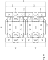
- a section can be defined, for example, by panels arranged one behind the other.
- the forming tools then preferably have several at least partially repeating or identical structures for processing the substrate or the sections or individual panels.
- the speeds of the cylinders are adjusted during a cylinder revolution so that at least partially different speeds prevail when the sections pass through the processing point.
- the processing lengths of the individual panels or of the entire sheet can therefore be lengthened or shortened.
- the processing length can then be corrected for each panel. This is done section by section by regulating and/or controlling the speed ratios between the sheet and the forming unit.
- the division can be set, for example, at a control station before a print job.
- the division into sections is particularly advantageous if it is automated by an inspection device, which carries out the division and transmits the data to a control unit.
- the speed ratio of the forme cylinder to the counter cylinder differs at least once, preferably several times, in one cylinder revolution.
- the advantage of adjusting the processing length in sections is that the machine can be adjusted more flexibly to the materials to be processed.
- a sequence is stored in the machine control system so that an operator only has to specify correction values for each section.
- the machine adjusts the Processing lengths, especially the speed ratios.
- a speed ratio is automatically adjusted from a correction value, for example using a look-up table.
- the print length can also be corrected in sections.
- the print length for individual panels can be determined or inspected by analyzing the print image and/or processing result.
- the printing cylinder can then be operated in different sections with different angular speeds or surface speeds.
- the print lengths can be lengthened or shortened in sections, for example for each individual panel or the entire sheet.
- the order form preferably has at least partially repeating structures. By increasing the speed, the print image can be shortened and by decreasing it, the print image can be lengthened. This shortening or lengthening of the print image takes place in the respective sections.
- section-by-section correction of the processing length and the section-by-section correction of the printing length can create a processing machine with increased flexibility and adjustment options.
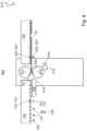
- a processing machine 01 is preferably designed as a printing machine 01 and/or as a shaping machine 01, in particular a punching machine 01.
- the printing machine 01 is preferably designed as a flexographic printing machine 01.
- the processing machine 01 is preferably referred to as a printing machine 01 if it has at least one application unit 614, preferably designed as a printing unit 614, and/or at least one printing unit 600, in particular regardless of whether it has further units for processing substrate 02.
- a processing machine 01 designed as a printing machine 01 additionally has at least one further such unit 900, for example at least one shaping unit 900, which is preferably designed as a punching unit 900, more preferably as a punching device 900.
- the processing machine 01 is preferably referred to as a shaping machine 01 if it has at least one shaping unit 914 and/or at least one shaping unit 900, in particular regardless of whether it has further units 600 for processing substrate 02.
- the processing machine 01 is preferably referred to as a punching machine 01 if it has at least one punching machine 914 designed as a shaping machine 914 and/or at least one punching unit 900 and/or at least one punching device 900, in particular regardless of whether it has further units 600 for processing substrate 02.
- a processing machine 01 designed as a shaping machine 01 or punching machine 01 additionally has at least one further unit 600 for processing substrate 02, for example at least one printing unit 600 and/or at least one printing unit 614.
- the processing machine 01 in particular a sheet processing machine 01, preferably comprises a unit 100 designed as a sheet feeder 100 and/or at least one printing unit 614 designed as an application unit 614 for applying at least one print image to substrate 02. If the processing machine 01 has at least one printing unit 614 and/or at least one printing unit 600 on the one hand and at least one shaping unit 914 and/or at least one shaping unit 900 on the other hand, it is therefore designed both as a printing machine 01 and as a shaping machine 01.
- the processing machine 01 has at least one printing unit 614 and/or at least one printing unit 600 on the one hand and at least one punching unit 914 and/or at least one punching unit 900 and/or at least one punching device 900 on the other hand, it is therefore designed both as a printing machine 01 and as a shaping machine 01, in particular a punching machine 01.
- the processing machine 01 is designed as a sheet processing machine 01, i.e. as a processing machine 01 for processing sheet-shaped substrate 02 or sheets 02, in particular sheet-shaped printing material 02.
- the sheet processing machine 01 is designed as a sheet-fed printing machine 01 and/or as a sheet forming machine 01 and/or as a sheet punching machine 01.
- the processing machine 01 is further preferably designed as a corrugated cardboard sheet processing machine 01, i.e. as a processing machine 01 for processing sheet-shaped substrate 02 or sheets 02 made of corrugated cardboard 02, in particular sheet-shaped printing material 02 made of corrugated cardboard 02.
- the processing machine 01 is further preferably designed as a sheet-fed printing machine 01, in particular as a corrugated cardboard sheet printing machine 01, i.e. as a printing machine 01 for coating and/or printing sheet-shaped substrate 02 or sheets 02 made of corrugated cardboard 02, in particular sheet-shaped printing material 02 made of corrugated cardboard 02.
- the printing machine 01 is designed as a printing machine operating according to a printing form-based printing process. Printing machine 01 trained.
- the term sheet-shaped substrate 02 in particular a printing material 02, specifically the sheet 02, is intended to include in principle any substrate 02 that is present in a flat form and in sections, i.e. also substrates 02 that are present in panel or plate form, i.e. also panels or plates.
- the sheet-shaped substrate 02 or the sheet 02 defined in this way is made, for example, of paper or cardboard, i.e. as a paper or cardboard sheet, or by sheets 02, panels or possibly plates made of plastic, cardboard, glass or metal.
- the substrate 02 is more preferably corrugated cardboard 02, in particular corrugated cardboard sheets 02.
- the at least one sheet 02 is designed as corrugated cardboard 02.
- the thickness of a sheet 02 is preferably understood to mean a dimension orthogonal to a largest area of the sheet 02. This largest area is also referred to as the main area.
- pressure fluid is applied to the sheet 02 at least partially and/or at least on one side of the at least one main surface.
- the thickness of the sheets 02 is, for example, at least 0.1 mm (zero point one millimeter), more preferably at least 0.3 mm (zero point three millimeters) and even more preferably at least 0.5 mm (zero point five millimeters).
- Significantly greater thicknesses are also common, for example at least 4 mm (four millimeters) or even 10 mm (ten millimeters) and more.
- Corrugated cardboard sheets 02 are comparatively stable and therefore not very flexible. Appropriate adjustments to the processing machine 01 therefore make it easier to process sheets 02 of great thickness.
- sheet 02 refers to both those sheets 02 that have not yet been processed by means of at least one shaping device 900 and those sheets 02 that have already been processed by means of the at least one shaping device 900 and/or by means of at least one separation device 903 and have possibly been changed in their shape and/or their mass.
- a front edge 03 e.g. front edge 03 of the sheet 02, is preferably the edge 03 of the sheet 02 with which the sheet 02 in question first encounters an assembly 100; 300; 600; 700; 900; 1000 during transport through the processing machine 01.
- the front edge 03 is preferably oriented along the transport path within the processing machine 01 parallel to a direction A, in particular transverse direction A and/or orthogonal to a direction T, in particular transport direction T.
- a direction Y is preferably oriented perpendicular to the front edge 03 of the sheet 02, which is preferably oriented parallel to a side edge of the sheet 02, in particular in the case that the sheet 02 in question has a rectangular shape.
- the direction Y is preferably oriented parallel to the transport direction T and/or orthogonal to the transverse direction A.
- the sheet 02 preferably has a rear edge 04, e.g. trailing edge 04, with which the sheet 02 in question last encounters an aggregate 100; 300; 600; 700; 900; 1000 during transport through the processing machine 01.
- the rear edge 04 is arranged parallel to the front edge 03 of the sheet 02.
- a direction X is oriented parallel to the front edge 03 of the sheet 02, which is preferably oriented orthogonally to a side edge of the sheet 02, in particular when the sheet 02 in question has a rectangular shape.
- the direction X is preferably oriented parallel to the transverse direction A and/or orthogonal to the transport direction T.
- Two side edges of the sheet 02 and the front edge 03 of the sheet 02 and the rear edge 04 of the sheet 02 preferably limit the main surface of the sheet 02.
- the respective sheet 02 is made of paper or cardboard or carton. Further preferably, the respective sheet 02 is made of cardboard, preferably corrugated cardboard.
- paper is a flat material consisting essentially of fibers, usually of plant origin, which is formed by dewatering a fiber suspension on a sieve. This creates a fiber felt, which is then dried.
- the area-related mass of paper is preferably a maximum of 225 g/m 2 (two hundred and twenty-five grams per square meter).
- cardboard is a flat material consisting essentially of fibers of plant origin, which is formed by dewatering a fiber suspension on one or between two sieves. The fiber structure is compressed and dried.
- Cardboard is preferably made by gluing or pressing together cellulose and/or. Cardboard is preferably in the form of solid cardboard or corrugated cardboard 02.
- Corrugated cardboard 02 in the foregoing and in the following is cardboard made of one or more layers of corrugated paper that is glued to a layer or between several layers of another, preferably smooth, paper or cardboard.
- the area-related mass of cardboard is preferably over 225 g/m 2 (two hundred and twenty-five grams per square meter).
- cardboard refers to a paper sheet that is preferably coated on one side, preferably with a mass per unit area of at least 150 g/m 2 (one hundred and fifty grams per square meter) and a maximum of 600 g/m 2 (six hundred grams per square meter).
- Cardboard preferably has a high strength relative to paper.
- application fluid includes inks and printing inks, but also primers, varnishes and pasty materials.
- Application fluids are preferably materials that are transferred and/or can be transferred to a substrate 02, in particular a printing material 02, for example to at least one sheet 02, by a processing machine 01, in particular a printing machine 01, or at least one application unit 614 or an assembly 600 of the processing machine 01 designed as an application unit 600, in particular at least one printing unit 614 or printing assembly 600 of the printing machine 01, and in doing so, preferably in a finely structured form and/or not only over a large area, create a preferably visible and/or perceptible by sensory impressions and/or machine-detectable texture on the substrate 02, in particular the printing material 02.
- Inks and printing inks are preferably solutions or dispersions of at least one colorant in at least one solvent, for example water. and/or organic solvents.
- the application fluid can be designed as an application fluid that crosslinks under UV light.
- Inks are relatively low-viscosity application fluids and printing inks are relatively high-viscosity application fluids.
- Inks preferably have no binding agent or relatively little binding agent, while printing inks preferably contain relatively high amounts of binding agent and more preferably further auxiliary substances.
- colorless varnishes are also meant in particular when application fluids and/or inks and/or printing inks are mentioned.
- agents in particular primers, for pretreatment, so-called priming or precoating of the printing substrate 02 are also meant in particular when application fluids and/or inks and/or printing inks are mentioned.
- application fluid the terms printing fluid and coating agent are to be understood as synonymous.
- a respective application fluid is preferably not gaseous.
- a respective application fluid is preferably liquid and/or powdery.
- the processing machine 01 preferably has several units 100; 300; 600; 700; 900; 1000.
- An unit is preferably understood to be a group of devices that work together functionally, in particular in order to be able to carry out a preferably self-contained processing process of sheets 02.
- at least two and preferably at least three and more preferably all of the units 100; 300; 600; 700; 900; 1000 are designed as modules 100; 300; 600; 700; 900; 1000 or at least each assigned to one such module.
- a module is understood to mean in particular a respective unit or a structure made up of several units, which preferably has at least one means of transport and/or at least one of its own controllable and/or adjustable drive and/or is designed as an independently functional module and/or a machine unit or functional assembly manufactured and/or assembled separately.
- a separate controllable and/or adjustable drive of an unit or module is understood to mean in particular a drive which serves to to drive movements of components of this unit or module and/or which serves to effect a transport of substrate 02, in particular sheet 02, through this respective unit or module and/or through at least one area of action of this respective unit or module and/or which serves to directly or indirectly drive at least one component of the respective unit or module intended for contact with sheet 02.
- These drives of the units 100; 300; 600; 700; 900; 1000 of the processing machine 01 are preferably designed as position-controlled electric motors.
- each unit 100; 300; 600; 700; 900; 1000 has at least one drive control and/or at least one drive regulator which is assigned to the respective at least one drive of the respective unit 100; 300; 600; 700; 900; 1000.
- the drive controls and/or drive regulators of the individual units 100; 300; 600; 700; 900; 1000 can preferably be operated individually and independently of one another.
- the drive controls and/or drive regulators of the individual units 100; 300; 600; 700; 900; 1000 are and/or can be linked in terms of circuitry, in particular by means of at least one BUS system, to one another and/or to a machine control system of the processing machine 01 in such a way that a coordinated control and/or regulation of the drives of several or all units 100; 300; 600; 700; 900; 1000 of the processing machine 01 is and/or can be carried out.
- the individual units 100; 300; 600; 700; 900; 1000 and/or in particular modules 100; 300; 600; 700; 900; 1000 of the processing machine 01 are therefore preferably electronically coordinated and/or operated, at least with regard to their drives, in particular by means of at least one virtual and/or electronic master axis.
- the virtual and/or electronic master axis is specified for this purpose, for example by a higher-level machine control of the processing machine 01.
- the individual units 100; 300; 600; 700; 900; 1000 of the processing machine 01 are, at least with regard to their drives, for example mechanically synchronized with one another and/or synchronizable.
- the individual units 100; 300; 600; 700; 900; 1000 of the processing machine 01 are mechanically decoupled from one another, at least with regard to their drives.
- the virtual and/or electronic master axis preferably has a sequence of master axis signals that are equidistant in time. Each of these master axis signals corresponds to a point in time at which it is generated and/or a virtual angle value.
- These virtual angle values are preferably between 0° (zero degrees) and 360° (three hundred and sixty degrees) and are output in ascending order, in particular via the BUS system, with the cycle preferably starting again at 0° (zero degrees) when 360° (three hundred and sixty degrees) is reached.
- a sequence of angle values from 0° (zero degrees) to 360° (three hundred and sixty degrees) preferably corresponds to a machine cycle.
- the machine cycle preferably corresponds to a full revolution of a forme cylinder 616 of the application unit 614 and/or a distance between front edges 03 of successive sheets 02 transported at a constant and equal speed and/or the time interval between two points in time at which successive sheets 02 are each accelerated for the first time with at least one primary acceleration means 136.
- Master axis signals have, for example, intervals of 4 ms (four milliseconds).
- the transport path is preferably defined by at least one device for guiding the substrate 02 in an operating state of the processing machine 01.
- the units 100; 300; 600; 700; 900; 1000 of the processing machine 01 are preferably each characterized in that the section of a transport path provided for the transport of sheets 02 defined by the respective unit 100; 300; 600; 700; 900; 1000 is at least substantially flat and more preferably completely flat.
- a substantially flat section of the transport path provided for the transport of sheets 02 is to be understood as a section that has a minimum radius of curvature that is at least two meters, more preferably at least five meters, even more preferably at least ten meters, and even more preferably at least fifty meters.
- a completely flat section has an infinitely large radius of curvature and is thus also essentially flat and thus also has a minimum radius of curvature that is at least two meters.
- the units 100; 300; 600; 700; 900; 1000 of the processing machine 01 are each preferably characterized in that the section of the transport path intended for the transport of sheets 02 defined by the respective unit 100; 300; 600; 700; 900; 1000 runs at least essentially horizontally and more preferably exclusively horizontally.
- This transport path preferably extends in a direction T, in particular transport direction T.
- a transport path that runs essentially horizontally and is intended for the transport of sheets 02 means in particular that the intended transport path in the entire area of the respective unit 100; 300; 600; 700; 900; 1000 has only one or more directions that deviate from at least one horizontal direction by a maximum of 30° (thirty degrees), preferably a maximum of 15° (fifteen degrees) and more preferably a maximum of 5° (five degrees).
- the transport path intended for the transport of sheets 02 preferably begins at a point where the sheets 02 are removed from a feeder stack 104.
- the direction T of the transport path is in particular the direction T in which the sheets 02 are transported at the point at which the direction T is measured.
- the transport direction T provided in particular for transporting sheets 02 is preferably the direction T which is preferably at least substantially and more preferably completely horizontally oriented and/or which preferably points from a first unit 100; 300; 600; 700; 900; 1000 of the processing machine 01 to a last unit 100; 300; 600; 700; 900; 1000 of the processing machine 01, in particular from a Sheet feeder unit 100 or a substrate feed device 100 on the one hand to a delivery unit 1000 or a substrate delivery device 1000 on the other hand, and/or which preferably points in a direction in which the sheets 02 are transported apart from vertical movements or vertical components of movements, in particular from a first contact with an unit 300; 600; 700; 900; 1000 of the processing machine 01 arranged downstream of the substrate feed device 100 or first contact with the processing machine 01 to a last contact with the processing machine 01.
- the feed device 300 is an independent
- a direction A is preferably a direction A oriented orthogonal to the transport direction T of the sheets 02 and/or orthogonal to the intended transport path of the sheets 02 through the at least one application unit 600 and/or through the at least one shaping unit 900 and/or through the at least one sheet delivery 1000.
- the transverse direction A is preferably a horizontally oriented direction A.
- a longitudinal axis of the at least one forme cylinder 616 is oriented parallel to the transverse direction A.
- a working width of the processing machine 01 and/or of the at least one application unit 600 and/or of the at least one shaping unit 900 and/or of the at least one sheet delivery 1000 is preferably a dimension which preferably extends orthogonally to the intended transport path of the sheets 02 through the at least one application unit 600 and/or the at least one shaping unit 900 and/or the at least one sheet delivery 1000, more preferably in the transverse direction A.
- the working width of the processing machine 01 preferably corresponds to a maximum width that a sheet 02 may have in order to still be compatible with the Processing machine 01 to be able to process it, i.e. in particular a maximum sheet width that can be processed with the processing machine 01.
- the width of a sheet 02 is to be understood in particular as its dimension in the transverse direction A, in particular the direction X. This is preferably independent of whether this width of the sheet 02 is larger or smaller than an orthogonal horizontal dimension of the sheet 02, which more preferably represents the length of this sheet 02 in the direction Y.
- the working width of the processing machine 01 preferably corresponds to the working width of the at least one application unit 600 and/or the at least one shaping unit 900 and/or the at least one sheet delivery 1000.
- the working width of the processing machine 01 is preferably at least 100 cm (one hundred centimeters), more preferably at least 150 cm (one hundred and fifty centimeters), even more preferably at least 160 cm (one hundred and sixty centimeters), even more preferably at least 200 cm (two hundred centimeters) and even more preferably at least 250 cm (two hundred and fifty centimeters).
- a vertical direction V preferably designates a direction that is arranged parallel to the normal vector of a plane spanned by the transport direction T and the transverse direction A.
- the vertical direction V is preferably oriented such that it points from the printing material 02 towards a forme cylinder 901 of the shaping device 900.
- the processing machine 01 preferably has at least one substrate feed device 100, which is further preferably designed as an aggregate 100, in particular a substrate feed aggregate 100 and/or as a module 100, in particular a substrate feed module 100.
- the at least one substrate feed device 100 is preferably designed as a sheet feeder 100 and/or sheet feeder aggregate 100 and/or sheet feeder module 100.
- the processing machine 01 has, for example, at least one unit designed as a conditioning device, in particular a conditioning unit, which is more preferably designed as a module, in particular as a conditioning module.
- a conditioning device is designed, for example, as a preparation device, in particular as a preparation device for applying primer, or as a post-treatment device, in particular as a post-treatment device for applying paint.
- the processing machine 01 preferably has at least one unit designed as a preparation device, in particular a preparation unit, which is more preferably designed as a module, in particular as a preparation module, and represents a conditioning device.
- the processing machine 01 preferably has at least one post-treatment device.
- the processing machine 01 preferably has at least one unit 300, preferably a system device 300, which is more preferably designed as a system unit 300 and/or system module 300.
- the at least one system device 300 is alternatively designed as a component of the substrate feed device 100 or another unit.
- the processing machine 01 has, for example, at least one unit 600, e.g. the application unit 600, which is preferably designed as a module 600, in particular application module 600.
- the at least one application unit 600 is preferably arranged and/or constructed depending on the function and/or application method.
- the at least one application unit 600 preferably serves to apply at least one respective application fluid or coating agent to the entire surface and/or at least part of the surface of the sheets 02.
- An example of an application unit 600 is a printing unit 600 or printing module 600, which in particular serves to apply printing ink and/or ink to the substrate 02, in particular sheets 02.
- a primer unit and/or a varnishing unit that may be arranged are also considered to be such an application unit 600 or printing unit 600.
- an application unit 600 is a form-based application unit 600, which in particular has at least one fixed, physical and preferably replaceable printing form for the application of printing fluid.
- Form-based application units 600 preferably work according to a planographic printing process, in particular offset planographic printing process and/or according to a gravure printing process and/or according to a letterpress process, particularly preferably according to a flexographic printing process.
- the corresponding application unit 600 is preferably a flexographic application unit 600 or flexographic printing unit 600, in particular flexographic application module 600 or flexographic printing module 600.
- the at least one application unit 600 is designed as an offset printing unit 600.
- the processing machine 01 has, for example, at least one unit designed as a drying device, in particular a drying unit, which is more preferably designed as a module, in particular as a drying module.
- at least one drying device 506 and/or at least one post-drying device is a component of at least one unit 100; 300; 600; 700; 900; 1000, preferably designed as a module 100; 300; 600; 700; 900; 1000.
- at least one application unit 600 has at least one drying device 506 and/or has at least one unit 700 designed as a transport device 700 and/or at least one unit 700 designed as a transport unit 700.
- the processing machine 01 preferably has at least one transport device 700, which is further preferably designed as an aggregate 700, in particular the transport aggregate 700, and/or as a module 700, in particular as a transport module 700.
- the transport device 700 is also referred to as a transport means 700.
- the processing machine 01 preferably has transport devices 700, for example as components of other units and/or modules.
- the processing machine 01 preferably has at least one shaping device 900, which is more preferably designed as an aggregate 900, in particular a shaping aggregate 900 or punching aggregate 900, and/or as a module 900, in particular as a shaping module 900 or punching module 900 and/or as a punching device 900.
- the processing machine 01 preferably has at least one shaping aggregate 900 designed as a punching aggregate 900.
- the at least one shaping device 900 is preferably designed as a rotary punching device 900 and/or preferably has at least one shaping unit 914 or punching unit 914.
- a shaping device 900 should also be understood to mean an embossing device and/or a creasing device.
- a perforating device is preferably also a form of a punching device 900.
- the processing machine 01 preferably has at least one unit 1000 designed as a substrate delivery device 1000, in particular a delivery 1000, in particular a sheet delivery 1000, in particular a delivery unit 1000, which is further preferably designed as a module 1000, in particular as a delivery module 1000.
- the processing machine 01 has, for example, at least one unit designed as a further processing device, in particular a further processing unit, which is further preferably designed as a module, in particular as a further processing module.
- the further processing unit is preferably arranged in the transport direction T after the at least one shaping device 900.
- the further processing unit is arranged in the transport direction T after the at least one sheet delivery 1000.
- the at least one further processing device is in each case designed as a gluing device and/or folding device.
- the processing machine 01 preferably has transport means 119; 136; 700; 904; 906 at one or more locations. At least one of these transport means 119; 136; 700; 906 is preferably designed as a suction transport means 119; 136; 700; 906, in particular as a suction belt and/or as a suction box belt and/or as a roller suction system and/or as a suction roller.
- Such suction transport means 119; 136; 700; 906 preferably serve to move sheets 02 forward in a controlled manner and/or to enable movements while sheets 02 are held against at least one counter-pressure surface of the corresponding suction transport means 119; 136; 700; 906.
- a relative negative pressure is preferably used to pull and/or press the sheets 02 against at least one transport surface.
- a transport movement of the sheets 02 is generated by a corresponding, in particular circumferential, movement of the at least one transport surface.
- the sheet 02 is held in its path by the at least one suction transport means 119; 136; 700; 906, for example along the transport path provided for the transport of sheets 02, and a transport movement of the sheet 02 is generated by a force predetermined by another, for example upstream and/or downstream transport means 119; 136; 700; 904; 906.
- the negative pressure is in particular a negative pressure relative to an ambient pressure, in particular relative to an atmospheric pressure.
- the suction transport means 119; 136; 700; 906 is therefore preferably understood to mean a device which has at least one counter-pressure surface, which is further preferably designed as a sliding surface and/or as a particularly movable transport surface and which is, for example, at least partially movable at least in the transport direction T. Furthermore, the respective suction transport means 119; 136; 700; 906 preferably has at least one vacuum chamber, which is further preferably connected to at least one vacuum source by means of a suction line.
- the vacuum source has, for example, a Blower.
- the at least one vacuum chamber has at least one suction opening that serves to suck in the sheets 02.
- the sheets 02 are sucked into a position that closes the at least one suction opening or are only sucked against a counter-pressure surface in such a way that ambient air can still get past the sheets 02 into the suction opening.
- the transport surface has one or more suction openings.
- the suction openings preferably serve to convey a negative pressure from the suction opening of the vacuum chamber to the transport surface, in particular without pressure losses or with very low pressure losses.
- the suction opening acts on the sheets 02 in such a way that they are sucked against the transport surface without the transport surface having suction openings.
- At least one deflection means is arranged that directly or indirectly ensures a circumferential movement of the at least one transport surface.
- the at least one deflection means and/or the transport surface itself is driven and/or drivable, in particular to ensure a movement of the sheets 02.
- the transport surface allows sheets 02 to slide along the transport surface.
- a first embodiment of a suction transport means 119; 136; 700; 906 is a suction belt.
- a suction belt is understood to mean a device that has at least one flexible conveyor belt, the surface of which serves as a transport surface.
- the at least one conveyor belt is preferably deflected by deflection means designed as deflection rollers and/or deflection rolls and/or is preferably self-contained, in particular in such a way that an endless circulation is possible.
- the at least one conveyor belt preferably has a plurality of suction openings.
- the at least one conveyor belt preferably covers the at least one suction opening of the at least one vacuum chamber in at least one section of its circulation path.
- the vacuum chamber is then further preferably connected to an environment and/or to Sheet 02 is connected.
- Support means are preferably arranged which prevent the at least one conveyor belt from being pulled too far or at all into the vacuum chamber and/or which ensure that the transport surface assumes a desired shape, for example such that it forms a flat surface at least in the area in which its suction openings are connected to the vacuum chamber.
- a circumferential movement of the at least one conveyor belt then results in a forward movement of the transport surface, with sheets 02 being held securely on the transport surface precisely in the area in which they lie opposite the suction opening covered by the at least one conveyor belt with the exception of the suction openings.
- a second embodiment of a suction transport means 119; 136; 700; 906 is a roller suction system.
- a roller suction system is understood to mean a device in which the at least one transport surface is formed from at least sections of the lateral surfaces of a large number of transport rollers and/or transport rollers. The transport rollers and/or transport rollers thus each form, for example, closed and/or rotating parts of the transport surface.
- the roller suction system preferably has a large number of suction openings. These suction openings are preferably arranged at least between adjacent transport rollers and/or transport rollers.
- at least one cover mask is arranged, which preferably represents a boundary of the vacuum chamber. The cover mask preferably has the large number of suction openings.
- the cover mask preferably forms a substantially flat surface.
- the transport rollers and/or transport rollers are preferably arranged in such a way that they are intersected by this flat surface and more preferably only protrude a small part, for example only a few millimeters, beyond this flat surface, in particular in a direction facing away from the vacuum chamber.
- the suction openings are then preferably designed in the shape of a frame and surround at least one of the transport rollers and/or transport rollers.
- the transport unit 700 is designed as at least one suction transport means 700.
- a suction transport means 700 comprises at least two roller suction systems, which are preferably each designed as an individually driven roller suction system.
- the roller suction system is also referred to as a suction box.
- a third embodiment of a suction transport means 119; 136; 700; 906 is a suction box belt.
- a suction box belt is understood to be a device that has a plurality of suction boxes, in particular those that can move in a rotating manner and each have an outer surface that serves as a transport surface.
- a fourth embodiment of a suction transport means 119; 136; 700; 906 is at least one suction roller.
- a suction roller is understood to be a roller whose outer surface serves as a transport surface and has a plurality of suction openings and which has at least one vacuum chamber in its interior, which is connected to at least one vacuum source, for example by means of a suction line.
- a fifth embodiment of a suction transport means 119; 136; 700; 906 is at least one sliding suction device.
- the sliding suction device is preferably designed as a passive transport means and serves in particular to specify boundary conditions with regard to a position of a respective sheet 02 without setting the sheet 02 itself in motion.
- the respective sliding suction device preferably has at least one sliding surface and at least one vacuum chamber and at least one suction opening. This at least one sliding surface then serves as a counter-pressure surface and serves as a transport surface.
- the transport surface designed as a sliding surface is preferably not moved.
- the sliding surface serves as a counter-pressure surface, are pressed against the corresponding sheets 02.
- the sheets 02 can still be moved along the sliding surface, in particular if they are otherwise subjected to a force that is at least parallel to the sliding surface.
- a force that is at least parallel to the sliding surface For example, an area between two driven suction transport means 119; 136; 700; 906 can be bridged by means of a sliding suction device.
- suction transport means 119; 136; 700; 906 can, for example, have at least one common vacuum source and/or at least one common vacuum chamber and/or at least and/or work together as a suction transport means 119; 136; 700; 906 and/or be arranged one behind the other and/or next to one another. Such combinations are then preferably assigned to at least two of the embodiments of suction transport means 119; 136; 700; 906.
- a section of the transport path provided for the transport of sheets 02 which is defined by the respective suction transport means 119; 136; 700; 906, is located below the particularly movable transport surface, which serves in particular as a counter-pressure surface and is, for example, at least partially movable at least in the transport direction T.
- the respective suction transport means 119; 136; 700; 906 is then designed as an upper suction transport means 700; 906, wherein more preferably its suction openings or intake openings preferably also or only point downwards at least during their connection to the at least one vacuum chamber and/or its suction effect is preferably also or only directed upwards.
- the sheets 02 are then transported by the suction transport means 119; 136; 700; 906, preferably hanging.
- the at least one transport unit 700 is designed as an upper suction transport means 700.
- the at least one transport means 906 is designed as an upper suction transport means 906.
- a section of the transport path provided for the transport of sheets 02 which is defined by the respective suction transport means 119; 136; 700; 906, is located above the particularly movable transport surface, which serves in particular as a counter-pressure surface and is, for example, at least partially movable at least in the transport direction T.
- the respective suction transport means 119; 136; 700; 906 is then designed as a lower suction transport means 119; 136; 700; 906, wherein more preferably its suction openings or suction openings preferably also or only point upwards, at least during their connection to the at least one vacuum chamber, and/or its suction effect is preferably also or only directed downwards.
- the sheets 02 are then transported by the suction transport means 119; 136; 700; 906, preferably lying down.
- at least two suction transport means 119; 136 as lower suction transport means 119; 136.
- the processing machine 01 for processing sheets 02 comprises the at least one application unit 600 and at least one sheet sensor 622 assigned to the respective application unit 600.
- the processing machine 01 is preferably designed as a sheet processing machine 01 with the substrate feed device 100 and the at least one application unit 600 and the at least one shaping device 900 and more preferably with the at least one delivery 1000 arranged along the transport path provided for the transport of sheets 02 after the at least one shaping device 900.
- the substrate feed device 100 preferably comprises the feed unit 300.
- the feed unit 300 preferably has at least one feeder stack 104.
- the feeder stack 104 preferably comprises a plurality of sheets 02, which are preferably at least temporarily stacked in a storage area 166.
- the storage area 166 is preferably delimited by at least one front stop 137.
- the front stop 137 is preferably designed such that a single sheet 02 can be transported in the vertical direction V below the front stop 137 in the transport direction T.
- the at least one transport means 136 preferably designed as an acceleration means 136, is assigned to the storage area 166.
- the acceleration means 136 is preferably designed as a lower suction transport means 136.
- the acceleration means 136 preferably serves to accelerate sheets 02 of the feeder stack 104 to a target transport speed, in particular a processing speed, of sheets 02, with which the sheets 02 are preferably transported within the processing machine 01 for processing of the sheets 02 by the units 100; 300; 600; 700; 900; 1000.
- the transport means 119 designed as a secondary acceleration means 119 is preferably arranged after the acceleration means 136 in the transport direction T.
- the secondary acceleration means 119 is preferably designed as a transport belt and/or transport roller, more preferably as a lower suction transport means 119.
- the secondary acceleration means 119 is preferably designed to adapt an actual transport speed of sheets 02 to the processing speed as soon as their actual transport speed deviates from the processing speed.
- the at least one transport unit 700 in particular a first transport unit 700, is preferably arranged.
- At least one transfer means is preferably provided in the transport unit 700 designed as a transport unit.
- the at least one application unit 600 with the at least one application unit 614 designed as a printing unit 614 is preferably arranged.
- the at least one application unit 600 has the at least one printing unit 614 with the forme cylinder 616 and an individual drive 631; 630 assigned to the forme cylinder 616.
- the at least one application unit 600 is preferably designed as a flexo application unit 600 or as an offset printing unit 600.
- the processing machine 01 preferably has at least four application units 600, in particular flexo application units 600.
- the processing machine 01 comprises at least six application units 600, wherein the individual application units 600 preferably differ at least partially in the printing fluid processed by them and/or a print image element applied by them to the printing material 02.
- the at least one transport means 700 is arranged between each two application units 600.
- the at least one printing unit 614 is preferably designed as a flexographic printing unit, which is designed in particular according to the principle of the flexographic printing process for applying printing fluid to the sheet 02.
- the application unit 614 comprises the at least one forme cylinder 616, at least one impression cylinder 617, at least one anilox roller 618 and at least one ink fountain 619.
- the ink fountain 619 preferably has printing fluid and is designed to deliver the printing fluid to the anilox roller 618.
- the anilox roller 618 is designed to transfer the printing fluid to at least one printing form of the forme cylinder 616 for printing on a printing material 02.
- the forme cylinder 616 and the impression cylinder 617 preferably define a processing point 621 of the application unit 614.
- the processing point 621 designed as a printing gap 621 is preferably defined, through which preferably sheet 02 the printing unit 614.
- the printing gap 621 is preferably the area in which the respective forme cylinder 616 on the one hand and the respective impression cylinder 617 on the other hand are closest to each other.
- the printing unit 614 has at least one forme cylinder 616.
- the forme cylinder 616 has at least one printing forme and at least one holder 626 for the at least one printing forme.
- the holder 626 of the printing forme is designed, for example, as a clamping device.
- the holder 626 of the printing forme is preferably designed along a circumferential direction of the outer surface of the forme cylinder 616 as a non-printing region of the outer surface of the forme cylinder 616.
- the non-printing region of the forme cylinder 616 preferably has a length in the circumferential direction of the forme cylinder 616 which is preferably at least 3%, preferably at least 5%, more preferably at least 8%, of the circumferential length of the forme cylinder 616.
- the length of the non-printing region is preferably determined by the length in the circumferential direction of the printing region of the forme cylinder 616, in particular the length of the at least one printing form in the circumferential direction of the forme cylinder 616.
- the non-printing region corresponds to a cylinder channel of the at least one forme cylinder 616.
- the non-pressing area of the outer surface of the forme cylinder 616 there is preferably no transfer of pressure fluid from the outer surface of the forme cylinder 616 to sheet 02 during printing operation of the processing machine 01.
- a transfer of pressure fluid from the forme cylinder 616 to sheet 02 preferably only takes place within that area of the outer surface of the forme cylinder 616 which has the at least one printing form. That area of the outer surface of the forme cylinder 616 which has the at least one printing form is preferably designed as the printing area of the outer surface of the forme cylinder 616.
- the at least one printing form is preferably further preferably exactly one printing form, and the at least one non-printing area, preferably exactly one non-printing area, arranged one behind the other.
- the holder 626 is preferably arranged in front of the printing area of the forme cylinder 616, more preferably a rear edge of the non-printing area of the forme cylinder 616 is arranged in front of the printing area of the forme cylinder 616 in the direction of rotation of the forme cylinder 616.
- a front edge of the printing area of the forme cylinder 616 is identical to the rear edge of the non-printing area of the forme cylinder 616.
- the unit 600 has a further cylinder, preferably designed as a rubber cylinder, between the at least one forme cylinder 616 and the at least one impression cylinder 617.
- the forme cylinder 616 is preferably designed to be drivable and/or driven by the drive designed as an individual drive 631.
- the individual drive 631 of the forme cylinder 616 is preferably designed as a preferably position-controlled electric motor 631.
- the forme cylinder 616 is driven mechanically independently of each other cylinder and/or roller of the printing unit 614.
- the impression cylinder 617 it preferably has a surface that is continuous along a circumferential direction of the impression cylinder 617. This is the case, for example, if the impression cylinder 617 has a sleeve as a jacket surface.
- the impression cylinder 617 in this embodiment is designed to be drivable by the individual drive 630 of the forme cylinder 616 in addition to the forme cylinder 616.
- the impression cylinder 617 preferably has a separate individual drive, in particular a preferably position-controlled electric motor 630.
- the impression cylinder 617 is driven by a drive of the virtual and/or electronic Leading axis driven and/or drivable.
- the impression cylinder 617 which has a continuous surface, has a circumference which differs from the circumference of the forme cylinder 616 assigned to it, preferably which is smaller than the circumference of the forme cylinder 616 assigned to it.
- the impression cylinder 617 it is preferably designed as a plate cylinder and additionally or alternatively preferably has at least one impression plate.
- the diameter of the impression cylinder 617 designed as a plate cylinder preferably corresponds to the circumference of the forme cylinder 616.
- the impression cylinder 617 has at least one holder 627 for fastening the at least one impression plate.
- the holder 627 of the impression cylinder 617 preferably has the same size along the outer surface of the impression cylinder 617 as the holder 626 along the outer surface of the forme cylinder 616.
- the holder 627 of the impression cylinder 617 is preferably arranged along the outer surface of the impression cylinder 617 in such a way that when the impression cylinder 617 rotates in accordance with the processing speed and the forme cylinder 616 rotates in accordance with the processing speed, the positions of the holders 626; 627 are designed to be synchronized with one another.
- the holders 626; 627 arrive at the respective printing gap 621 at the same time as a front edge of the holders 626; 627 during a rotational movement associated with the processing speed.
- the holders 626; 627 are designed to leave the respective printing gap 621 at the same time as a rear edge of the holders 626; 627 during a rotational movement associated with the processing speed.
- At least one first application unit 600 in the transport direction T is designed as a priming unit and/or at least one last application unit 600 in the transport direction T is designed as a painting unit.
- the at least one shaping device 900 with the at least one shaping unit 914 is preferably arranged.
- the at least one shaping device 900 is preferably designed as a punching device 900 and/or as a rotary punching device 900.
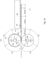
- the at least one shaping device 900 preferably has at least one and more preferably exactly one processing station 910, preferably designed as a shaping point 910, which is formed by at least and more preferably exactly one forme cylinder 901, in particular designed as a punching forme cylinder 901, on the one hand, and at least one counter-pressure cylinder 902 on the other hand.
- the shaping point 910 is preferably the area in which the respective forme cylinder 901 on the one hand and the respective counter-pressure cylinder 902 on the other hand are closest to each other.
- the at least one shaping point 910 is preferably designed as at least one punching point 910.
- the shaping device 900, in particular the shaping unit 914 preferably comprises at least one tool, more preferably the at least one forme cylinder 901 comprises at least one tool.
- the tool of the shaping device 900, in particular of the shaping unit 914, preferably the tool of the forme cylinder 901 is at least temporarily in direct contact with the counter-pressure cylinder 902, in particular in the area of the shaping point 910.
- the at least one punching impression 1103 is designed, for example, as a groove and/or ridge and/or embossing and/or cut and/or perforation.
- the at least one punch impression 1103, in particular if it is designed as a perforation and/or cut is designed to at least partially separate at least one blank 1101 from at least one waste piece and/or from at least one further blank 1101.
- a sheet 02 which is processed by the shaping device 900, i.e. which is arranged on the transport path in the transport direction T after the at least one shaping point 910 has at least one blank 1101, preferably at least two blanks 1101, and at least one waste piece.
- the term panel 1101 preferably refers to the number of identical objects according to DIN 16500-2 that are made from the same piece of material and/or are arranged on a common carrier material, for example a common sheet 02.
- a panel 1101 is preferably that area of a sheet 02 that is designed as a product of the sheet processing machine 01, in particular as an intermediate product for producing an end product, for example as a blank, and/or is further processed into the desired or required end product and/or is designed to be further processed.
- the at least one panel 1101 of the respective sheet 02 has the at least one printed image.
- the desired or required end product that was produced by the respective panel 1101 or preferably by further processing the respective panel 1101 is a folding box and/or a lidded box and/or a folding sleeve and/or a dimensionally stable box.
- a residual piece preferably a waste piece, is in the foregoing and in the following that area of a sheet 02 which does not correspond to a blank 1101.
- a residual piece is preferably designed as a waste piece and/or trimming and/or break-out and is preferably designed to be at least partially removable from at least one blank 1101.
- the at least a waste piece is produced at the at least one shaping point 910 of the shaping device 900, for example in at least one punching process, and preferably at least partially, preferably completely, removed from the respective sheet 02 during operation of the sheet processing machine 01.
- the sheet processing machine 01 is preferably characterized in that the at least one separation device 903 for removing at least one piece of waste from at least one sheet 02 is arranged along the transport path provided for the transport of sheets 02 after the at least one shaping point 910.
- the separation device 903 is preferably designed to completely remove pieces of waste from the respective sheet 02.
- the at least one separation device 903 therefore serves in particular to separate the remaining pieces, in particular the former parts of the sheet 02 that have already been completely or partially separated from the sheet 02 and are to be removed from the sheet 02, from use 1101, in particular those parts of the sheet 02 that are to continue to be treated as sheets 02 and, if necessary, further processed.
- the at least one separation device 903 is designed, for example, as a separation unit 903 and/or as a separation module 903. Alternatively, the at least one separation device 903 is part of another unit 900 or module 900, in particular of the at least one shaping unit 900 or shaping module 900.
- the at least one separation device 903 preferably has at least one transport means 904 designed as a separation transport means 904, in particular for transporting sheets 02.
- the at least one separation transport means 904 preferably serves to transport respective sheets 02 along the transport path provided for the transport of sheets 02 and/or in the transport direction T, while waste pieces are removed from the respective sheets 02.
- the waste pieces are preferably transported in a respective direction which has at least one Component that is oriented orthogonal to the transport direction T, preferably opposite to a vertical direction V, for example vertically downwards.
- at least gravity is also used to remove such waste pieces from the respective sheet 02.
- a force needs to be applied that separates the respective waste piece from the respective sheet 02 and gravity then carries the respective waste piece away in a direction that has at least one component that is oriented orthogonal to the transport direction T, preferably downwards.
- exactly one separation transport means 904 is arranged along the transport path provided for the transport of sheets 02.
- several separation transport means 904 are arranged along the transport path provided for the transport of sheets 02, which are designed differently, for example.
- the sheet processing machine 01 is preferably characterized in that the at least one separation transport means 904 is designed to act on sheets 02 and/or is capable of acting on them both from above and from below. Sheets 02 can then be transported with sufficient accuracy along the transport path provided for the transport of sheets 02 despite the action of the at least one separation device 903.
- the sheet processing machine 01 is preferably characterized in that the at least one separation transport means 904 has a plurality of upper separation transport belts arranged next to one another at a distance relative to the transverse direction A and/or a plurality of lower separation transport belts arranged next to one another at a distance relative to the transverse direction A.
- Separation transport belts are designed, for example, as endless and/or revolving belts, which more preferably have a relatively small dimension in the transverse direction A, for example less than 5 cm (five centimeters), preferably less than 2 cm (two centimeters) and more preferably less than 1 cm (one centimeter).
- the sheet processing machine 01 is preferably characterized in that the at least one separation transport means 904 is different from any suction transport means, i.e. is not designed as a suction transport means.
- the sheet processing machine 01 is preferably characterized in that the at least one separation device 903 is designed as at least one vibrating device 903 and/or that the at least one separation device 903 has at least one vibrating drive.
- at least one separation transport belt can be deflected orthogonally to its local transfer direction by means of the at least one vibrating drive.
- a local transfer direction is to be understood as the direction in which a respective element of the respective separation transport belt is moved due to a circular movement of the respective separation transport belt, in particular apart from any superimposed deflection movements.
- the at least one vibrating drive is therefore preferably used to vibrate the respective sheet 02, in particular by movements in directions orthogonal to the transport direction T. Such movements are only necessary with a small deflection, for example.
- the at least one vibrating drive is arranged to act directly or indirectly on the at least one separation transport means 904 and/or at least one separation transport belt and/or to be capable of acting thereon, for example via at least one impact wave.
- the at least one vibrating drive is arranged to act directly or indirectly on at least one deflection means and/or at least one guide means of at least one separation transport belt. and/or capable of acting.
- at least one electric and/or at least one pneumatic and/or at least one hydraulic and/or at least one magnetic drive is arranged as the vibration drive.
- the at least one separation device 903 has, for example, at least one separation blower, which further preferably serves to remove waste pieces from the respective sheets 02 by means of at least one gas flow that is activated at least temporarily.
- the sheet processing machine 01 is preferably characterized in that at least one transport means 906 designed as a selective transport means 906 is arranged along the transport path provided for the transport of sheets 02, in particular along the transport path provided for the transport of sheets 02 after the at least one separation transport means 904.
- the at least one transport means 906 designed as a selective transport means 906 is preferably arranged along the transport path provided for the transport of sheets 02 adjacent to the at least one separation transport means 904, in particular directly adjacent to the at least one separation transport means 904.
- a selective transport means 906 is to be understood in particular as a transport means 906 that only transports and/or is designed to be capable of transporting selected objects, for example exclusively sheets 02 and/or no leftover pieces.
- the at least one selective transport means 906 is designed as at least one upper suction transport means 906 for a hanging transport of sheets 02, more preferably as at least one exclusively upper suction transport means 906 and/or for an exclusively hanging transport of sheets 02. Then, even after the at least one separation transport means 904, any remaining pieces can still fall away against the vertical direction V, preferably downwards, and move away from the sheets 02 without to disrupt subsequent processes.
- the sheet processing machine 01 is characterized in that the sheet processing machine 01 has at least one transport means 906, in particular an upper suction transport means 906, along the transport path provided for the transport of sheets 02 in the transport direction T after the separation device 903, which is designed for the hanging transport of sheets 02, preferably for the hanging transport of the at least one remaining part of the at least one sheet 02 with the at least one blank 1101 that has been processed by the shaping device 900.
- the sheet processing machine 01 has at least one transport means 906, in particular an upper suction transport means 906, along the transport path provided for the transport of sheets 02 in the transport direction T after the separation device 903, which is designed for the hanging transport of sheets 02, preferably for the hanging transport of the at least one remaining part of the at least one sheet 02 with the at least one blank 1101 that has been processed by the shaping device 900.
- the at least one substrate delivery device 1000 is preferably arranged.
- the substrate delivery device 1000 preferably comprises at least one delivery stack carrier 48 and at least one diversion delivery device 51.
- the substrate delivery device 1000 designed as delivery device 1000 preferably has at least one preferably adjustable and/or controllable sheet switch 49, which is designed to guide sheets 02 either to the delivery stack carrier 48 or the diversion delivery device 51.
- At least one transport means designed as a sheet braking means is arranged, which is further preferably arranged at least partially and further preferably completely above a delivery stack carrier of the sheet delivery 1000.
- the at least one sheet braking means serves in particular to brake sheets 02 before they are deposited on a delivery stack on the delivery stack carrier 48.
- the sheet processing machine 01 is preferably characterized in that in the transport direction T in front of the delivery 1000 preferably at least one Change in the transport path provided for the transport of sheets 02, in particular the sheet switch 49, is regulated and/or controlled and/or designed to be controllable and/or adjustable.
- the change in the transport path is preferably designed to eject and/or deflect sheets 02 onto a transport path that bypasses the actual transport path.
- the change in the transport path, in particular the sheet switch 49 is preferably designed to eject and/or deflect sheets 02 onto a transport path that bypasses the at least one sheet braking means.
- the change in the transport path serves, for example, to eject at least one sheet 02, in particular a sample sheet to be examined and/or at least one waste sheet.
- a waste sheet has at least one defect that makes it different from a target state of sheet 02.
- the sheet processing machine 01 is further preferably characterized in that the change in the transport path, in particular the at least one sheet switch 49, for discharging sheets 02 onto a transport path bypassing the at least one sheet braking means is arranged along the transport path provided for the transport of sheets 02 between the at least one separation device 903 on the one hand and the at least one sheet braking means on the other hand.
- the sheet processing machine 01 is preferably characterized in that the delivery 1000, preferably the sheet delivery 1000, has at least one front stack limiter and/or that a delivery stack area is limited at least by the at least one rear sheet stop and the at least one front stack limiter and/or that the sheet delivery 1000 has at least one upper sheet transport system designed for a hanging transport of sheets 02, which has at least one overlapping device and/or that the at least one overlapping device of an overlapping for an overlapped, hanging transport of at least two sheets 02 on at least one in vertical The location above the delivery stack area as viewed in direction V.
- a sheet 02 which is arranged on the transport path in the transport direction T after the at least one shaping point 910 and after the at least one separation device 903, preferably has at least one blank 1101, preferably at least two blanks 1101, and at least one sheet opening 1102, preferably at least two sheet openings 1102.
- the at least one blank 1101 of the respective sheet 02 each has the at least one printed image.
- the sheet 02 has at least two blanks 1101, each with the at least one printed image.
- the at least two blanks 1101 of the respective sheet 02 each have at least one, preferably identical, printed image.
- a sheet 02 which is arranged on the transport path in the transport direction T after the at least one shaping point 910 and after the at least one separation device 903 and is additionally or alternatively arranged outside the sheet processing machine 01 after passing through the sheet processing machine 01, has at least one blank 1101, preferably at least two blanks 1101, wherein at least one remaining piece, preferably at least two remaining pieces, have been removed from the sheet 02.
- the sheet 02 additionally has at least one punching impression 1103, preferably at least two punching impressions 1103, in particular a punching impression 1103 designed as a groove and/or score and/or embossing.
- the sheet 02 has no remaining pieces in the transport direction T after the separation device 903 or after passing through the sheet processing machine 01.
- Different blanks 1101 are designed to be separable from one another and/or separated within a sheet 02, for example by at least one punched impression 1103, for example a perforation and/or an at least partial cut and/or a groove.
- a sheet 02 in the transport direction T after the separation device 903 has no waste pieces.
- a sheet 02 in the transport direction T after the separation device 903 has a sheet opening 1102 at each of the positions of the waste pieces, the dimensions and/or contour of which correspond to the dimensions and/or contour of the respective removed waste piece.
- the dimensions and/or contour of a sheet opening 1102 correspond to the dimensions and/or contour of several adjacent waste pieces.
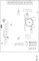
- the processing machine 01 has at least one inspection device 726; 728; 916.
- the remaining contour of the sheet 02 corresponds to the contour of the at least one remaining piece removed before the inspection device 916 and/or a combined contour of at least two remaining pieces removed before the inspection device 916.
- sheet opening 1102 preferably designates, in an actual state of the relevant sheet 02, a region of sheet 02 in which, after the at least one processing operation in the shaping device 900 and additionally or alternatively after the at least one processing operation in the separation device 903, the relevant sheet 02 preferably has no mass, preferably a gap.
- the sheet opening 1102 is designed as a sheet gap 1102.
- at least one waste piece of the relevant sheet 02 can be assigned and/or is assigned to a respective sheet opening 1102.
- a sheet opening 1102 is that region of a sheet 02 from which at least one piece of waste has been removed and/or in which the sheet 02 has lost mass and/or has no remaining mass compared to a point in time before the at least one processing operation in the shaping device 900 and additionally or alternatively before the at least one processing operation in the separation device 903.
- two opposing boundaries of the respective sheet opening 1102, in particular two opposite edges of the respective sheet 02 for delimiting the respective sheet opening 1102 are spaced apart from one another by a distance greater than zero, preferably greater than 5 mm (five millimeters), more preferably greater than 10 mm (ten millimeters), more preferably greater than 20 mm (twenty millimeters), more preferably greater than 30 mm (thirty millimeters).
- the at least one respective sheet opening 1102 is designed as a handle in the desired or required end product, which was produced by the respective blank 1101 or its further processing.
- the print image describes a representation on the printing material 02 which corresponds to the sum of all print image elements, in particular all image-forming elements, wherein the individual print image elements are transferred and/or can be transferred to the printing material 02 during at least one work stage and/or at least one printing process.
- at least one print image element can be transferred to the printing material 02 by an application unit 600 of the processing machine 01.
- the image-forming element is preferably an element which can be transferred to the sheet 02 by at least one application unit 600 of the processing machine 01 and which, in the sum of all image-forming elements, results in the print image.
- the second reference positions 11; 12; 13; 14 are preferably arranged next to one another in the Y direction and/or one behind the other in the X direction.
- a first reference position 06; 07; 08; 09 is preferably arranged next to one another in the Y direction and/or one behind the other in the X direction relative to a second reference position 11; 12; 13; 14.
- the sheet processing machine 01 preferably comprises at least one sheet sensor 164; 622; 722; 922.
- the processing machine 01 has a plurality of sheet sensors 164; 622; 722; 922, which are preferably at least partially arranged one behind the other in the transport direction T.
- the at least one sheet sensor 164 is designed as a sheet start sensor 164 or the at least one sheet sensor 622; 922 is designed as a sheet travel sensor 622; 922 or the at least one sheet sensor 722 is designed as a sheet control sensor 722.
- the sheet sensor 622; 722; 922 is arranged at the same coordinate with respect to the transverse direction A.
- the sheet sensors 622; 722; 922 are arranged one behind the other in the transport direction T, preferably in alignment with one another.
- An arrangement of the sheet sensors 622; 722; 922 in the transport direction T in alignment with one another preferably ensures that the same position of the front edge 03 and/or rear edge 04 of the respective sheet 02 can be detected by the respective sheet sensors 622; 722; 922.
- the sheet processing machine 01 is alternatively or additionally characterized in that the at least one sheet sensor 164; 622; 722; 922 is designed to detect a position and/or location of the respective sheet 02.
- the at least one sheet sensor 164; 622; 722; 922 is designed to detect a position and/or location of the respective sheet 02.
- the respective sheet sensor 164; 622; 722; 922 is preferably designed to be mechanically movable in relation to the transverse direction A.
- the respective sheet sensor 164; 622; 722; 922 is designed to detect the respective leading edge 03 and/or the respective trailing edge 04 and/or the at least one respective imaging element, for example the register mark 16; 17; 18; 19; 21; 22; 23; 24, of the respective sheet 02 and preferably to send a corresponding signal. Further preferably, the at least one sheet sensor 164; 622; 722; 922 is designed simultaneously as a leading edge sensor and as a trailing edge sensor.
- At least one sensor element 171; 623; 723; 923 of these at least two sensor elements 171; 172; 623; 624; 723; 724; 923; 924 is designed as a transmitter 171; 623; 723; 923, in particular as a transmitter 171; 623; 723; 923 for electromagnetic radiation.
- At least a sensor element 172; 624; 724; 924 of these at least two sensor elements 171; 172; 623; 624; 723; 724; 923; 924 is designed as a receiver 172; 624; 724; 924, in particular as a receiver 172; 624; 724; 924 for electromagnetic radiation and/or as a receiver 172; 624; 724; 924 assigned to the at least one transmitter 171; 623; 723; 923.
- at least one reflector is arranged, which is also a sensor element.
- At least one sensor element 171; 172; 623; 624; 723; 724; 923; 924 of the sheet sensor 164; 622; 722; 922 is arranged above the transport path provided for the transport of sheets 02 and at least one sensor element 171; 172; 623; 624; 723; 724; 923; 924 of the sheet sensor 164; 622; 722; 922 is arranged below the transport path provided for the transport of sheets 02.
- the sheet sensor 164; 622; 722; 922 which is preferably designed as a transmitted light sensor, preferably has a particularly high reaction speed and thus preferably enables a particularly precise checking of the transport of sheets 02.
- the at least one sheet sensor 164; 622; 722; 922 has a sampling frequency which is at least 2 kHz (two kilohertz), more preferably at least 5 kHz (five kilohertz), even more preferably at least 9 kHz (nine kilohertz), even more preferably at least 19 kHz (nineteen kilohertz), and even more preferably at least 29 kHz (twenty-nine kilohertz).
- the processing machine 01 preferably has the substrate feed device 100 with the at least one sheet sensor 164.
- the at least one sheet sensor 164 of the substrate feed device 100 designed as a sheet start sensor 164 is arranged in alignment with the intended transport path for detecting a respective front edge 03 and/or a respective rear edge 04 and/or at least one register mark 16; 17; 18; 19; 21; 22; 23; 24 and/or at least part of the print image of respective sheets 02.
- the feed device 300 has the at least one sheet sensor 164 designed as a sheet start sensor 164.
- the processing machine 01 is preferably characterized in that the at least one sheet sensor 164 designed as a sheet start sensor 164 is arranged downstream of the at least one primary acceleration means 136 and/or downstream of the at least one front stop 137 and/or upstream of the at least one secondary acceleration means 119 in relation to the transport direction T.
- the processing machine 01 is preferably characterized in that the at least one sheet sensor 164, in particular the at least one sheet start sensor 164, is arranged in the region of the at least one secondary acceleration means 119 in relation to the transport direction T.
- the sheet sensor 164 designed as a sheet start sensor 164 is arranged such that its detection area has an intersection with a control section 167 of the transport path provided for the transport of sheets 02.
- the control section 167 preferably begins at a start point 168, which lies along the transport path provided for the transport of sheets 02 after the storage area 166, and/or preferably ends at an end point 169, which lies along the transport path provided for the transport of sheets 02 in front of the at least one application unit 600.
- the processing machine 01 only comprises a shaping device 900
- the control section 167 preferably ends at the end point 169, which lies along the transport path provided for the transport of sheets 02 in front of the at least one processing point 910, preferably designed as a shaping point 910.
- the control section 167 preferably defines an area that is suitable for an advantageous arrangement of the detection area of the at least one sheet sensor 164.
- the sheet processing machine 01 is alternatively or additionally characterized in that the starting point 168 has an initial distance from the storage area 166 which is at least 50 mm (fifty millimeters), more preferably at least 90 mm (ninety millimeters), more preferably at least 120 mm (one hundred and twenty millimeters), more preferably at least 140 mm (one hundred and forty millimeters) and more preferably at least 145 mm (one hundred and forty-five millimeters).
- the closer the starting point 168 and/or the detection range of the at least one sheet start sensor 164 is to the storage area 166 the sooner an accelerated sheet 02 can be detected and the sooner a corresponding measurement result can be responded to.
- By maintaining a minimum distance it is preferably ensured that the sheet 02 to be detected already has the desired transport speed when it is detected, in particular the corresponding processing speed.
- the sheet processing machine 01 is alternatively or additionally characterized in that the end point 169 has a final distance from the at least one, in particular first, processing point 621 that is at least 200 mm (two hundred millimeters), more preferably at least 250 mm (two hundred and fifty millimeters), more preferably at least 290 mm (two hundred and ninety millimeters), more preferably at least 320 mm (three hundred and twenty millimeters), more preferably at least 340 mm (three hundred and forty millimeters) and more preferably at least 350 mm (three hundred and fifty millimeters).
- the end point 169 has an end distance from the at least one, more preferably from the first and even more preferably from each transport means 700 arranged in the transport direction T after the secondary acceleration means 119, which is at least 200 mm (two hundred millimeters), more preferably at least 250 mm (two hundred and fifty millimeters), more preferably at least 290 mm (two hundred and ninety millimeters), even more preferably at least 320 mm (three hundred and twenty millimeters), even more preferably at least 340 mm (three hundred and forty millimeters) and even more preferably at least 350 mm (three hundred and fifty millimeters). It is then ensured that compensating accelerations of the respective sheet 02 are completed before the sheet 02 engages the transport means 700, which is more preferably operated at a constant speed, in particular at the processing speed.
- the respective initial distance and/or the respective final distance preferably results from the maximum sheet length of the sheets 02 to be processed with the sheet processing machine 01 and/or from the maximum processing speed at which the sheet processing machine 01 is to be operated.
- the initial distance is preferably at least as large as an acceleration distance on which the respective sheets 02 can be and/or are accelerated to the processing speed by means of the at least one primary acceleration means 136.
- the final distance is at least as large as a distance that sheet 02 covers at the processing speed in the time necessary to calculate and execute a respective compensation process.
- the sheet processing machine 01 is alternatively or additionally characterized in that the at least one secondary acceleration means 119 has at least three conveyor belts arranged next to one another at a distance from one another with respect to a transverse direction A and further preferably that a detection range of the at least one sheet start sensor 164 is located between the at least three conveyor belts arranged next to one another at a distance from one another with respect to the Transverse direction A extends along conveyor belts arranged next to one another at a distance from one another.
- the at least one secondary acceleration means 119 has at least three conveyor belts arranged next to one another at a distance from one another with respect to a transverse direction A and further preferably that a detection range of the at least one sheet start sensor 164 is located between the at least three conveyor belts arranged next to one another at a distance from one another with respect to the Transverse direction A extends along conveyor belts arranged next to one another at a distance from one another.
- each sheet 02 is assigned a movement profile that can be represented as a function in which a position of the respective sheet 02 along the transport path provided for the transport of sheet 02 is described as a function of the progression of the sequence of master axis values.
- the detection time is preferably assigned, for example, to a master axis value. It can then be compared at what time or master axis value the sheet 02 would have been expected at the at least one sheet sensor 164. From a possible value deviation, it is preferably concluded how this sheet 02 must be transported, for example, by means of the at least one secondary acceleration means 119, so that the value deviation can be compensated as far as possible or completely eliminated.
- the respective sheet 02 is preferably adapted to the processing speed, especially in the case of a previous value deviation.
- the processing machine 01 preferably has at least two sheet start sensors 164, which are preferably arranged orthogonally to the transport path of sheets 02, which are further preferably arranged one behind the other in the transverse direction A and/or further preferably arranged next to each other in the transport direction T.
- the at least two sheet sensors 164 which are designed in particular as sheet start sensors 164, are preferably designed to detect an inclined position of sheets 02.
- these at least two sheet start sensors 164 which are arranged one behind the other in the transverse direction A, are each designed to detect the front edge 03 and/or the Trailing edge 04 and/or the at least one register mark 16; 17; 18; 19; 21; 22; 23; 24 and/or at least part of the print image of a respective sheet 02.
- the sheet processing machine 01 is alternatively or additionally characterized in that at least two sheet sensors 164 are arranged, the detection areas of which differ in their position relative to the transverse direction A. Then, a skew measurement of the respective sheet 02 is preferably carried out.
- the detection areas of these at least two sheet sensors 164 preferably have the same position relative to the transport direction T up to a tolerance of at most 10 mm (ten millimeters), more preferably at most 5 mm (five millimeters) and more preferably at most 2 mm (two millimeters). If the skew is too great, for example, compensation or sorting or marking of the corresponding sheet 02 or a machine stop takes place.
- the at least one sheet sensor 622 designed as a sheet travel sensor 622 is preferably arranged directly in front of the respective assigned application unit 600 with the respective forme cylinder 616, preferably in the transport direction T.
- the at least one sheet sensor 622 is designed to regulate and/or control the position and/or speed of the respective forme cylinder 616.
- the sheet sensor 622 is arranged to regulate the machine speed.
- the at least one sheet sensor 622 is arranged to control and/or regulate a drive means of a transport device 700. The speed of the sheets 05 is thus preferably adjusted using the signal from the sheet sensor 622.
- At least one sheet sensor 622 is assigned to the at least one application unit 600, more preferably at least two application units 600, more preferably each application unit 600.
- at least one sheet sensor 922 is assigned to the at least one application unit 600, more preferably at least two application units 600, more preferably each application unit 600.
- at least one sheet sensor 922 in particular the sheet travel sensor 922.
- the sheet travel sensor 622 is arranged in the transport direction T in front of the associated application unit 600 and/or the sheet travel sensor 922 is arranged in the transport direction T in front of the associated shaping unit 900.
- the at least one sheet sensor 622; 922 is designed to detect the arrival time of sheet 02 at the position of the sheet sensor 622; 922.
- the processing machine 01 which is preferably designed as a sheet-fed printing press 01, is preferably characterized in that the at least one sheet sensor 622; 922, designed as a sheet travel sensor 622; 922, is preferably arranged directed towards the intended transport path at least for detecting the respective arrival time of sheet 02, in particular the arrival time of the respective leading edge 03 and/or at least one register mark 16; 17; 18; 19; 21; 22; 23; 24 and/or at least part of the print image of the respective sheet 02.
- the sheet processing machine 01 is characterized in that the respective sheet travel sensor 622; 922 is arranged in the transport direction T in front of the respective processing station 621; 910.
- the sheet travel sensors 622; 922 which are each assigned to an application unit 600 or a shaping unit 900, are arranged at the same position in relation to the transverse direction A. This ensures that the same position of the front edge 03 and/or the rear edge 04 and/or the at least one register mark 16; 17; 18; 19; 21; 22; 23; 24 and/or of at least one part of the print image of the respective sheet 02 can be detected.
- the respective sheet travel sensor 622; 922 is arranged on a transport device 700 arranged in the transport direction T preferably directly in front of the respective unit 600; 900.
- the respective sheet travel sensor 622; 922 is arranged such that between the respective sheet travel sensor 622; 922 and the at least part of the transport device 700, in particular at least part of the relevant transport means 700, is arranged at the relevant processing point 621; 910 of the relevant unit 600; 900.
- the transport means 700 is designed as an upper suction transport means 700, in particular as the at least one roller suction system.
- At least one transport roller and/or at least one transport roller, more preferably additionally a maximum of three transport rollers and/or three transport rollers, of the upper suction transport means 700 are then arranged with respect to the transport direction T between the respective sheet travel sensor 622; 922 and the processing point 621; 910 of the relevant unit 600; 900.
- the respective sheet travel sensor 622; 922 preferably has a minimum distance of at least 200 mm (two hundred millimeters), preferably at least 300 mm (three hundred millimeters), more preferably at least 350 mm (three hundred and fifty millimeters), even more preferably at least 400 mm (four hundred millimeters) from the processing point 621; 910 assigned to it.
- the respective sheet travel sensor 622; 922 preferably has a maximum distance of a maximum of 650 mm (six hundred and fifty millimeters), more preferably a maximum of 600 mm (six hundred millimeters), even more preferably a maximum of 550 mm (five hundred and fifty millimeters), even more preferably 450 mm (four hundred and fifty millimeters) from the processing point 621; 910 assigned to it.
- the respective sheet travel sensor 622 which is assigned to an application unit 600, has a smaller distance from the respective processing point 621 than the respective sheet travel sensor 922, which is assigned to a shaping unit 900.
- the minimum distance of the sheet travel sensor 622; 922 from the respective processing point 621; 910 preferably ensures that there is a sufficiently long stretch of the transport path between the sheet travel sensor 622; 922 and the respective processing point 621; 910 in order to align the arrival time of the sheet 02, in particular the leading edge 03, with the leading edge of the printing area of the forme cylinder 616.
- the maximum distance of the sheet travel sensor 622; 922 from the respective processing point 621; 910 preferably ensures that the transport path between the sheet travel sensor 622; 922 and the respective processing point 621; 910 is as short as possible in order to avoid further influencing the speed of the sheet 02 and thus influencing its arrival time by the transport path.
- the respective at least one sheet travel sensor 622; 922 is designed to detect the arrival time of the sheets 02, in particular the arrival time of the leading edge 03 and/or the at least one register mark 16; 17; 18; 19; 21; 22; 23; 24 and/or at least part of the print image of the sheets 02, preferably before the respective sheet 02 reaches the relevant processing point 621; 910 of the associated unit 600; 900.
- each sheet 02 is assigned a movement profile that can be represented as a function in which a position of the respective sheet 02 along the transport path provided for the transport of sheet 02 is described as a function of the progression of the sequence of master axis values. If a sheet 02 is now detected by means of the at least one sheet sensor 622; 922, in particular the at least one sheet travel sensor 622; 922, the detection time is preferably assigned to a master axis value, for example. Then, a comparison is preferably made as to the time or master axis value at which the sheet 02 would have been expected at the at least one sheet sensor 622; 922.
- the at least one image capture device of the print image control system 726 is designed at least for capturing the at least one imaging element on the sheet 02, for example at least a part of the print image of the sheet 02 and/or at least one register mark 16; 17; 18; 19; 21; 22; 23; 24.
- the print image control system 726 is designed at least to detect the at least one imaging element of the sheet 02 with an area of at least 0.1 mm 2 (zero point one square millimeter).
- the at least one print image control system 726 in particular the at least one image capture device of the print image control system 726, is directed towards the transport path of sheet 02 such that the at least one print image which can be applied to sheet 02 by the at least one application unit 600 can be at least partially captured by the print image control system 726, in particular the at least one image capture device of the print image control system 726, and preferably additionally evaluated.
- the print image control system 726 is preferably arranged above the transport path and/or the transport plane, in particular in the vertical direction V after the transport path and/or the transport plane.
- the sheet 02 can be at least partially, preferably completely, detected and/or inspected from above by the print image control system 726.
- the at least one print image is preferably arranged on the main surface of the sheet 02 pointing upwards.
- the at least one print image of the sheet 02 can be at least partially, preferably completely, detected and/or inspected and/or evaluated by the print image control system 726 in this embodiment.
- the print image control system 726 is preferably arranged below the transport path and/or the transport plane, in particular in the vertical direction V in front of the transport path and/or in front of the transport plane.
- the print image control system 726 is preferably designed to at least partially, preferably completely, capture and/or inspect the sheet 02 from below. In the hanging guidance of sheet 02, this is at least a print image is preferably arranged on the main surface of the sheet 02 pointing downwards.
- the print image control system 726 is preferably designed to detect and/or inspect the at least one print image of the sheet 02 at least partially, preferably completely, from below, preferably in the vertical direction V from in front of the transport path and/or from in front of the transport plane.
- Possible errors in the sheets 02 are, for example, a curvature or unevenness of the sheet surface and additionally or alternatively holes or tears in the sheets 02 and additionally or alternatively creases in the sheets 02.
- the at least one inspection device 726; 728; 916 is designed at least as a register control system 728, in particular a color register control system 728.
- the register control system 728 is arranged in the transport direction T after the sheet control sensor 722, more preferably without a further application unit 600 or shaping unit 900 in between.
- the at least one inspection device 728 is arranged in the transport direction T after the at least one application unit 600, preferably in the transport direction T after the last application unit 600. More preferably, the register control system 728 is arranged in the transport direction T after the at least one application unit 600, preferably in the transport direction T after the last application unit 600, and before the at least one shaping unit 900, preferably before a first shaping unit 900.
- the at least one registration control system 728 is arranged in the transport direction T after the at least one print image control system 726, which then serves as the first inspection device 726 of the processing machine 01.
- the at least one registration control system 728 is arranged in the transport direction T in front of the at least one print image control system 726 and is then further preferably considered as the first inspection device 728 of the processing machine 01.
- the inspection device 728 designed as a registration control system 728 preferably comprises at least one preferably optical image capture device, preferably at least two preferably optical image capture devices, more preferably exactly two preferably optical image capture devices.
- the at least one image capture device is preferably designed as a camera, more preferably as a color camera, more preferably as a line camera, more preferably as a CMOS sensor and/or CCD sensor.
- the registration control system 728 preferably has at least one light source, for example an LED light source.
- the registration control system 728 preferably comprises at least one optical system, which is preferably arranged between the at least one image capture device and the transport path provided for the transport of sheets 02.
- the registration control system 728 comprises at least two image capture devices, preferably exactly two image capture devices, which are preferably arranged one behind the other in the transport direction T, preferably directly one behind the other in the transport direction T.
- the first image capture device of the registration control system 728 in the transport direction T is preferably designed to capture the at least one first register mark 16; 17; 18; 19 for each application unit 614 used, which is preferably arranged in the front area in the transport direction T of the main surface of the sheet 02 provided with at least one printed image.
- the second image capture device of the registration control system 728 in the transport direction T is preferably designed to capture the at least one second register mark 21; 22; 23; 24 for each application unit 614 used, which is preferably arranged in the rear region in the transport direction T of the main surface of the sheet 02 provided with at least one printed image.
- the first image capture device is designed to capture the at least one second register mark 21; 22; 23; 24 for each application unit 614 used and the second image capture device is designed to capture the at least one first register mark 16; 17; 18; 19 for each application unit 614 used.
- one image capture device is preferably designed to capture the at least one first register mark 16; 17; 18; 19 or the at least one second register mark 21; 22; 23; 24 for each application unit 614 used.
- the registration control system 728 is preferably arranged above the transport path and/or the transport plane, in particular in the vertical direction V after the transport path and/or the transport plane.
- the at least one register mark 16; 17; 18; 19; 21; 22; 23; 24 is preferably arranged on the main surface of sheet 02 pointing upwards.
- the at least one register mark 16; 17; 18; 19; 21; 22; 23; 24 of sheet 02 can be detected and/or inspected and/or evaluated at least partially, preferably completely, by the registration control system 728 in this embodiment.
- the at least one register mark 16; 17; 18; 19; 21; 22; 23; 24 of the sheet 02 is preferably designed to be at least partially, preferably completely, detected and/or inspected from below, preferably in the vertical direction V from in front of the transport path and/or from in front of the transport plane.
- the registration control system 728 in particular the at least one image capture device, is designed to capture at least part of the working width of the sheet processing machine 01.
- At least the register is at least partially inspected and/or evaluated and/or adjusted by the operating personnel, preferably using at least one sample sheet.
- An additional inspection device 728 designed as a register control system 728 is then preferably optional in the processing machine 01.
- the register of the application units 600 is adjusted to one another.
- a single sheet 02 or at least two sheets 02 or as few sheets 02 as possible pass through the units 100; 300; 600; 700; 900; 1000 of the processing machine 01 in the transport direction T.
- the register of the application units 600 to one another is preferably detected and/or regulated by the register control system 728.
- the register control system 728 preferably detects at least one register mark 16; 17; 18; 19; 21; 22; 23; 24, preferably all register marks 16; 17; 18; 19; 21; 22; 23; 24, of the respective sheet 02.
- the sheet 02 preferably has at least one register mark 16; 17; 18; 19; 21; 22; 23; 24 per application unit 614 at the reference position 06; 07; 08; 09; 11; 12; 13; 14 assigned to it. If the respective register mark 16; 17; 18; 19; 21; 22; 23; 24 deviates from its reference position 06; 07; 08; 09; 11; 12; 13; 14, a different change is necessary.
- any deviation of the register mark 16; 17; 18; 19; 21; 22; 23; 24 from its reference position 06; 07; 08; 09; 11; 12; 13; 14, which preferably describes a deviation of the register, is preferably recorded by the register control system 728 and additionally or alternatively evaluated.
- the deviation of the register is preferably recorded and/or evaluated by the operating personnel. If at least one of the register marks 16; 17; 18; 19; 21; 22; 23; 24 deviates from its reference position 06; 07; 08; 09; 11; 12; 13; 14, a change in the positioning of components of the processing machine 01 and/or the sheet guide and/or the speed of the sheets 02 is preferably carried out in accordance with the deviation.
- the forme cylinder 616 is regulated according to the existing deviation and/or the position of the forme cylinder 616 is changed and/or a sheet 02 following on the transport path is regulated.
- the first register mark 16; 17; 18; 19 and the second register mark 21; 22; 23; 24 of an associated application unit 614 is shifted by the distance ay to the respective reference position 06; 07; 08; 09; 11; 12; 13; 14, for example, the start of printing for the individual print image elements differs from one another and additionally or alternatively, for example, the Arrival time of the sheet 02, in particular the arrival time of the leading edge 03 of the sheet 02, from the arrival time of the printing form at the respective processing point 621 of the relevant application unit 614.
- the arrival time of the sheet 02, in particular the leading edge 03 of the sheet 02 is preferably synchronized and/or coordinated with the arrival time of the leading edge of the printing area of the corresponding forme cylinder 616.
- the corresponding forme cylinder 616 is accelerated and/or decelerated at least briefly by changing its speed and/or position, while the non-printing area is at least partially arranged at the processing point 621, so that the leading edge of the printing area of the forme cylinder 616 preferably arrives at the relevant processing point 621 at the same time as the leading edge 03 of the sheet 02.
- the corresponding forme cylinder 616 is accelerated and/or decelerated at least briefly by changing its rotational speed and/or position to change the register in the Y direction, in particular in the circumferential direction of the forme cylinder 616, while the non-printing region is at least partially arranged at the processing point 621.
- the first register mark 16; 17; 18; 19 and the respective second register mark 21; 22; 23; 24 of the same application unit 614 preferably have a displacement in the direction X at a distance ax from their respective reference position 06; 07; 08; 09; 11; 12; 13; 14.
- the first register mark 16; 17; 18; 19 and the second register mark 21; 22; 23; 24 are preferably in the direction X at a distance ax. 23; 24 of an associated application unit 614 is shifted by the distance ax to the respective reference position 06; 07; 08; 09; 11; 12; 13; 14, for example, the Printing form and/or the forme cylinder 616 of the respective application unit 614 is displaced relative to the sheet 02 in the transverse direction A.
- the forme cylinder 616 and/or the printing forme of the forme cylinder 616 of the respective application unit 614 is preferably displaced in the transverse direction A opposite to the direction in which the displacement occurs, preferably by the amount of the distance ax relative to the sheet 02.
- the forme cylinder 616 and/or the printing forme of the forme cylinder 616 of the respective application unit 614 is preferably designed to be adjustable in the transverse direction A opposite to the direction in which the displacement occurs, preferably by the amount of the distance ax relative to the sheet 02.
- the first reference position 06; 07; 08; 09 preferably has a reference length 11, in particular a reference length 11 designed as a reference path, between the second reference position 11; 12; 13; 14 of the same application unit 614.
- the first register mark 16; 17; 18; 19 preferably has the printing length I2, in particular the printing length I2 designed as a printing path, between the second register mark 21; 22; 23; 24 of the same application unit 614.
- the print length I2 is different from the reference length I1.
- the print length I2 deviates from the reference length I11
- the sheet 02 has a length in the direction Y, in particular within the Processing machine 01 has its length in the transport direction T, which differs from an original length of the sheet 02 before the at least one processing and/or before the application of pressure fluid.
- the length of the sheet 02 in the transport direction T along the transport path increases due to the at least one processing and/or the application of pressure fluid.
- the forme cylinder 616 in order to change the printing length I2 relative to the reference length I1, in particular to minimize a difference between the printing length I2 and the reference length I1, the forme cylinder 616 preferably has an at least partially changing speed, in particular peripheral speed, as long as at least part of the printing region of its outer surface is arranged at the processing point 621.
- the rotational speed and/or the peripheral speed of the forme cylinder 616 is changed relative to the rotational speed and/or the peripheral speed of the impression cylinder 617 assigned to it.
- the impression cylinder 617 has a higher peripheral speed than the forme cylinder 616.
- the change in the printing length I2 relative to the reference length I1 is preferably achieved by accelerating and/or braking the forme cylinder 616 by the individual drive of the forme cylinder 616, while the impression cylinder 617 is operated at a preferably constant peripheral speed.
- the respective printed image applied to the sheet 02 is stretched and/or compressed relative to the printing forme used for this purpose.
- the printed image on the sheet 02 is extended by a reduced peripheral speed of the forme cylinder 616 relative to the peripheral speed of the impression cylinder 617.
- the register in the circumferential direction of the forme cylinder 616 with regard to the printing length I2 can be adjusted by accelerating and/or braking the forme cylinder 616 by the individual drive of the forme cylinder 616, while the impression cylinder 617 is operated at a preferably constant peripheral speed.
- the first reference position 06; 07; 08; 09 has the reference distance to the second reference position 11; 12; 13; 14 of the same application unit 614.
- the first register mark 16; 17; 18; 19 has the printing path to the second register mark 21; 22; 23; 24 of the same application unit 614.
- the printing path is parallel, preferably identical, to the reference path in an ideally produced sheet 02.
- the printing path to the reference path preferably has an angle w, in particular a tilt angle w.
- the longitudinal axis of the forme cylinder 616 and/or the printing forme of the forme cylinder 616 of the respective application unit 614 is tilted relative to the transverse direction A, preferably relative to the sheet 02, by the tilt angle w.
- the respective forme cylinder 616 and/or the printing forme of the respective forme cylinder 616 is preferably tilted relative to the transverse direction A opposite to the tilt angle w, preferably with the same amount of the tilt angle w.
- the relevant forme cylinder 616 and/or the printing form of the relevant forme cylinder 616 is designed to be tiltable and/or adjustable relative to the transverse direction A against the tilt angle w, preferably with the same amount of the tilt angle w.
- sheets 02 are processed by the at least one unit 600; 900 of the processing machine 01.
- the respective sheet travel sensor 622 preferably detects the respective sheet 02 and thus determines its arrival time at the position of the respective sheet travel sensor 622.
- each sheet 02 which has the position of the relevant sheet travel sensor 622 is detected by the sheet travel sensor 622.
- the forme cylinder 616 assigned to the sheet travel sensor 622 is preferably regulated and/or controlled according to the time of arrival of the one relevant sheet 02 at the position of the sheet travel sensor 622, preferably so that the front edge 03 of the sheet 02 arrives at the processing point 621 of the relevant application unit 600 at the same time as the front edge of the printing area of the forme cylinder 616.
- the register control system 728 is also preferably used to adjust the speed of the cylinders of the application units 600. In particular, the register control system 728 is used to control and/or regulate the print length. The speed of the cylinders is preferably adjusted for this purpose.
- the inspection device 726; 728; 916 in particular the register control system 728, preferably detects the at least one register mark 16; 17; 18; 19; 21; 22; 23; 24, in particular the respective register marks 16; 17; 18; 19; 21; 22; 23; 24, of sheet 02 during the second printing process.
- the inspection device 726; 728; 916 in particular the register control system 728, preferably detects each sheet 02 that passes it.
- the inspection device 726; 728; 916, in particular the register control system 728 determines the deviation of the at least one register mark 16; 17; 18; 19; 21; 22; 23; 24 from its reference position 06; 07; 08; 09; 11; 12; 13; 14.
- the inspection device 726; 728; 916 From the determined deviations of at least two sheets 02, preferably of at least five sheets 02, more preferably of at least ten sheets 02, the inspection device 726; 728; 916, in particular the register control system 728, preferably forms an average deviation of the one register mark 16; 17; 18; 19; 21; 22; 23; 24 from its reference position 06; 07; 08; 09; 11; 12; 13; 14.
- the inspection device 726; 728; 916 outputs a signal, in particular a warning signal and/or control signal and/or control signal.
- the inspection device 726; 728; 916 regulates and/or controls the forme cylinder 616 assigned to the register mark 16; 17; 18; 19; 21; 22; 23; 24 by at least a brief change in the rotational speed and/or velocity, preferably at the average deviation in the Y direction of the register mark 16; 17; 18; 19; 21; 22; 23; 24 from its reference position 06; 07; 08; 09; 11; 12; 13; 14 by an amount exceeding the limit value, so that the front edge of the printing area of the forme cylinder 616 arrives at the relevant processing point 621 preferably at the same time as the front edge 03 of the sheet 02.
- the inspection device 726; 728; 916 preferably regulates and/or controls 916 a deflection of the respective sheet 02 from the actual transport path, for example to an alternative transport path and/or outputs at least one signal as soon as the deviation of the at least one register mark 16; 17; 18; 19; 21; 22; 23; 24 from its reference position 06; 07; 08; 09; 11; 12; 13; 14 exceeds the limit value.
- the time of arrival of the individual sheet 02 at the processing point 621 of the application unit 600 and the time of arrival of the front edge of the printing area of the forme cylinder 616 of this application unit 600 can be adjusted and/or is set by the signal of the sheet travel sensor 622 assigned to the application unit 600 for regulating and/or controlling the forme cylinder 616.
- the register in the Y direction preferably the register in the circumferential direction of the forme cylinder 616
- the register in the Y direction can be adjusted and/or is set by the signal of the sheet sensor 622 assigned to the application unit 600, in particular the sheet travel sensor 622, for regulating and/or controlling the forme cylinder 616.
- the regulation and/or control is carried out by the at least one signal of the inspection device 726; 728; 916 to correct the mean deviation of the register mark 16; 17; 18; 19; 21; 22; 23; 24 from its reference position 06; 07; 08; 09; 11; 12; 13; 14 exceeding the limit value
- the at least one signal of the inspection device 726; 728; 916 is followed by manual and/or mechanical regulation and/or control of the register in the circumferential direction if the average deviation of the register mark 16; 17; 18; 19; 21; 22; 23; 24 from its reference position 06; 07; 08; 09; 11; 12; 13; 14 exceeds the limit value.
- the regulation and/or control based on the sheet travel sensor 622 predominates over the regulation and/or control based on the inspection device 726; 728; 916 for changing the register in the Y direction, preferably the change of the register in the circumferential direction of the forme cylinder 616, in the second printing process.
- the processing machine 01 is designed such that the printing length I2 is changed and/or is designed to be changeable by changing the peripheral speed and/or rotational speed of the forme cylinder 616 relative to the peripheral speed and/or rotational speed of the counter-pressure cylinder 617 assigned to the respective forme cylinder 616.
- the processing machine 01 is designed such that the dimension of the printing length I2 detected by the at least one inspection device 726; 728; 916, in particular the deviation of the printing length I2 relative to the reference length 11, is changed and/or is designed to be changeable by changing the peripheral speed and/or rotational speed of the forme cylinder 616 relative to the peripheral speed and/or rotational speed of the counter-pressure cylinder 617 assigned to the respective forme cylinder 616.
- the processing machine 01 is preferably characterized in that the processing machine 01 has the shaping device 900 with the forme cylinder 901 with a single drive and the processing station 910 assigned to the forme cylinder 901.
- the forme cylinder 901 of the shaping device 900 is mechanically independent of each other Cylinder and/or roller of the forming device 900 and/or the processing machine 01 are driven.
- At least one further sheet sensor 922 is arranged along the transport path of sheet 02 in front of the processing point 910 of the forming device 900.
- the sheet sensor 922 is designed to regulate and/or control the position and/or the rotational speed of the forme cylinder 901 of the forming device 900.
- the at least one inspection device 726; 728; 916 is arranged along the transport path of sheet 02 after the forme cylinder 901 of the forming device 900, or the at least one further inspection device 916 is additionally arranged along the transport path of sheet 02 after the forme cylinder 901 of the forming device 900 for an at least partial inspection of sheet 02, preferably for an at least partial inspection of at least one remaining part of the at least one sheet 02 with at least one blank 1101 that has been processed by the forming device 900.
- the at least one inspection device 916 designed at least as a punching control system 916, is arranged along the transport path provided for the transport of sheets 02 for at least partial inspection of sheets 02, preferably for at least partial inspection of at least one remaining part of the at least one sheet 02 processed by the shaping device 900 with at least one blank 1101, preferably at least two blanks 1101.
- the inspection device 726; 728; 916 designed as a punch control system 916 is designed to at least partially inspect the contour of at least one remaining piece removed on the transport path in front of the punch control system 916 on the remaining sheet 02, in particular on the at least one blank 1101 and/or the at least one sheet opening 1102.
- the sheet processing machine 01 with a shaping device 900 for processing sheets 02 preferably comprises the at least one separation device 903 and the at least one delivery 1000, wherein the separation device 903 is designed to remove at least one remaining piece from the at least one sheet 02.
- the at least one punching control system 916 is arranged for the at least partial inspection of at least one remaining part of the at least one sheet 02 with the at least one blank 1101 that has been processed by the shaping device 900.
- the respective sheet 02 preferably has at least one blank 1101 with at least one printed image and at least one sheet opening 1102.
- the respective sheet 02 preferably has at least one blank 1101 and at least one sheet opening 1102, wherein the respective sheet 02 is formed from paper or cardboard or carton.
- the punch control system 916 is preferably designed to at least partially detect the at least one sheet opening 1102.
- the punch control system 916 preferably the evaluation means, is preferably designed to compare at least the at least one sheet opening 1102 with a reference of the at least one sheet opening 1102.
- the reference of the at least one sheet opening 1102 contains at least part of the information, preferably all information, which is necessary for a clear determination of a required target state of the relevant sheet opening 1102.
- the reference of the at least one sheet opening 1102 is designed as a digital and/or trained reference.
- the digital The reference is preferably designed as a digital image template.
- the digital reference preferably has a PDF or TIF or JPG file format.
- the trained reference is preferably a sheet 02 which is designed as a sample sheet and has at least one sheet opening 1102 which corresponds to the sheet opening 1102 to be inspected and/or is recorded, for example, by the punching control system 916 and/or is stored in the evaluation means as a basis for comparison.
- the inspection device 916 designed as a punch control system 916 preferably comprises at least one image capture device, preferably at least one optical image capture device.
- the at least one image capture device is preferably designed as a camera, more preferably as a color camera, more preferably as a line camera, more preferably as a CMOS sensor and/or CCD sensor.
- the punch control system 916 comprises at least one light source, for example at least one LED light source.
- the punch control system 916 preferably comprises at least one optical system, which is preferably arranged between the at least one image capture device and the transport path provided for the transport of sheets 02.
- the inspection device 726; 728; 916 thus inspects 916 the sheet 02 preferably from below.
- the inspection device 726; 728; 916 preferably detects at least a part of the transport path and/or at least a part of the transport plane and thus at least a part of the at least one sheet 02 which passes the inspection device 726; 728; 916 on the transport path in the transport direction T, at that position of the transport path and/or the transport plane towards which the inspection device 726; 728; 916 is directed, from below.
- the at least one print image is applied to the sheet 02 from below, that is to say in the vertical direction V in front of the sheet 02.
- the inspection device 726; 728; 916 preferably additionally or alternatively inspects the at least one print image of the sheet 02 from below, preferably in the vertical direction V from in front of the transport path and/or from in front of the transport plane.
- the method is preferably characterized in that the measurement for the position of the at least one blank 1101 relative to a reference of the position of the at least one blank 1101 and additionally or alternatively the measurement for the color of at least one print image of the respective sheet 02 and additionally or alternatively the measurement for at least one error in processing the respective sheet 02 and/or the at least one print image of the respective sheet 02 due to missing parts and/or additional parts is determined from the comparison of the actual state of the at least one sheet 02 with the target state of the respective sheet 02.
- the respective sheet 02 preferably has the at least one blank 1101 with the at least one printed image and the at least one sheet opening 1102, for example the at least one sheet gap 1102.
- the inspection device 726; 728; 916 preferably detects the at least one sheet opening 1102 at least partially.
- the inspection device 726; 728; 916, in particular the evaluation means, preferably compares at least the at least one sheet opening 1102 with the reference of the at least one sheet opening 1102.
- the respective sheet 02 preferably has the at least one blank 1101 and at least one sheet opening 1102.
- the respective sheet 02 is preferably made of paper or cardboard or carton.
- the inspection device 726; 728; 916 preferably detects the at least one sheet opening 1102 at least partially.
- the at least one sheet opening 1102 corresponds to at least a part of a residual piece removed from the respective sheet 02. Additionally or alternatively, the sheet opening 1102 was preferably created by removing at least a part of the at least one residual piece from the respective sheet 02.
- the method is preferably characterized in that the Inspection device 726; 728; 916 at least partially detects the at least one contour and/or the at least one shape and/or the at least one mass and/or the at least one area of the at least one sheet opening 1102.
- the method is preferably characterized in that the contour and/or shape and/or mass and/or area of the at least one sheet opening 1102 corresponds to the contour and/or shape and/or mass and/or area of the at least one remaining piece removed from the respective sheet 02.
- the method is preferably characterized in that the sheets 02 are changed in their shape in a respective shaping process.
- the respective shaping process is preferably a respective punching process in which the respective sheet 02 is punched, wherein in particular parts of the sheet 02 are removed.
- the processing length BL of a substrate 02 of the at least one shaping unit 900 is described in more detail below.
- the processing length BL is to be understood as the length of the entirety of the punched-out blanks 1101 of a substrate 02.
- the processing length BL can also be referred to as the punching length.
- a sheet 02 has several sections. Accordingly, a separate processing length BL1; BL2; BL3 can also be defined for each section. Such a section can be defined, for example, by a blank 1101.
- the processing length BL can then have several sections with their own processing lengths BL1; BL2, BL3...
- the processing length BL can be corrected as a whole or in sections if such are present.
- the formulation of the correction of the machining length BL also includes the section-by-section correction of the machining length.
- the processing length BL is corrected in several steps.
- a first initialization step a the processing length BL is divided into the intended sections. This is particularly useful when several blanks 1101 are arranged one behind the other on a sheet 02.
- the inspection step b an actual state is recorded.
- a third step c) the actual processing length is compared with the target values.
- the target values are usually stored in a machine control system.
- the comparison step d) a control variable is calculated from the deviation of the actual value.
- a speed ratio of a substrate 02 and a forming cylinder 901 is adjusted so that the processing length BL is corrected.
- the new actual value is then determined in a further step f) and used again as feedback to further adjust the processing length BL.
- the steps run automatically in a control loop.
- the initialization step a it is determined how many sections the processing length BL of the substrate 02 has. For this purpose, a value with the number n of sections is preferably transmitted to a control unit 1201 of the processing unit 914. The sections BL1; BL2; BL3 of the processing length BL can then be adjusted individually. In a preferred embodiment, the number n is entered at the control station 1202 of the processing machine 01 and transmitted to the control unit 1201. In another embodiment, the number n of sections is evaluated by means of an inspection device 916 and the data is automatically transmitted to the respective Control unit 1201. Additionally or alternatively, the number n from a job file, for example a PDF, can be used. For example, the number n can also be one and a processing length BL is then corrected as a whole. In addition, a total processing length can also be corrected if necessary for several sections.
- the number of sections is determined via the blanks 1101 arranged one behind the other on a sheet 02.
- the processing length BL can be corrected in sections so that each blank 1101 on the sheet 02 is adjusted individually.
- a sheet 02 has a first blank 1101 and a further blank 1101.
- the front blank 1101 is then assigned a first section of the processing length BL1 and the rear blank is assigned a second section of the processing length BL2.
- the blanks 1101 are preferably arranged directly one behind the other on a sheet 02. This offers the advantage that the sheet 02 retains its stability even after the shaping unit 900.
- the connected blanks 1101 can then be broken in a further step.
- webs can also be arranged between the panels 1101. As a rule, the webs are then either assigned to one of the sections or, in particular for a wide web, a new section is defined.
- the processing length BL is divided into sections in a process.
- a tool length of the forme cylinder 902 is stored in a machine control system.
- a form length or tool length is, for example, between 450 mm and 1600 mm.
- a processing length BL can be derived from this, whereby the processing length BL preferably corresponds to the tool length or the form length.
- a number of Sections are defined and transferred to a machine control system, for example by input at a control station 1202. From this, the processing lengths BL1; BL2 of the individual sections are calculated in a stored process.
- each section has a length BL1; BL2 of 500 mm.
- the sections are preferably each the same size. In a further preferred embodiment, the sections can also be of different sizes.
- the blanks 1101 are preferably arranged next to one another and/or one behind the other on a sheet 02. However, the blanks 1101 arranged one behind the other are generally not arranged overlapping and/or offset. Rather, the blanks 1101 lying one behind the other can be clearly separated. This is particularly advantageous for a downstream blank separation unit, since these connected blanks 1101 can then be separated from one another more easily.
- such a sheet 02 has at least one panel 1101, more preferably at least two panels 1101, even more preferably at least three, four or five panels 1101 on a sheet 02.
- the panels 1101 are preferably arranged so that they can be clearly separated by straight lines. An offset preferably does not occur for a precise division of the sections or is not helpful for a precise correction of the processing length BL.
- a control station 1202 has an input mask 930 for entering the tool values or the tool shape.
- a job name 931 and a job symbol 936 are stored in such an input mask 930.
- the number 933 of the blanks 1101 on a sheet 02 can be specified. More important for the correction is the number 932 of the blanks 1101 over the circumference of the form cylinder 901 or the forming tool 915.
- data about the dimensions of the tool 915 can be stored. For example, data about the width and length of the tool can be stored for the respective job.
- further information 941 can be stored in the input mask 950. For example, special features such as a special symmetry or a center cut or no knives, can be entered.
- the data can be saved for each order and stored in a list.
- the input mask 950 has a navigation bar. Several symbols 942 are arranged on this navigation bar. By pressing the symbols 942 I can jump from one input mask 950 to another.
- the at least one form cylinder 901 has at least one shaping tool 915 with at least one working surface 909.
- the at least one shaping tool 915 is mounted on a mounting plate 919.
- a form cylinder 901 of a shaping unit 900 has a plurality of holes 920 and/or bores 920 to which the mounting plate 919 and/or the shaping tool 915 can be directly mounted.
- the working surface 909 of the shaping tool 915 is defined as a surface whose position in the radial direction runs through the outermost tool shapes.
- the shaping tool 915 has a plurality of processing elements 921, preferably punching elements 921. Such punching elements 921 can be designed as punching knives, for example.
- the punching elements have a height of between 10 and 30 mm.
- the working surface 909 has a dimension in the circumferential direction.
- the working surface 909 preferably runs from a tool start 918 to a tool end 917.
- the tool start 918 is preferably defined by the beginning of elevations of processing elements 921 and/or punching elements 921 and/or tool parts, in particular punching knives, which are provided for processing a substrate 02.
- a working surface 909 is preferably between 30% and 90% of the outer surface of the forme cylinder 901. Covering here means in particular the projection of the working surface 909 directly onto the outer surface in the radial direction.
- the working surface 909 can also be defined via an input mask from a value for the A working surface 909 can be determined from the cutting.
- the working surface 909 can preferably be divided into several sections with lengths AL1; AL2; AL3... in the circumferential direction.
- the working surface 909 of the shaping tool 915 has several sections with working lengths AL1; AL2; AL3... for processing sections arranged one behind the other on a substrate 02.
- the number of sections depends on the number n of processing sections of the order or the sections on a sheet. Accordingly, each processing length of a section BL1, BL2, BL3... is assigned a section length AL1; AL2; AL3 of the working surface.
- the lengths of the processing length BL1; BL2; BL3... are also assigned a surface, in particular a counter surface with a length GL in the circumferential direction on the at least one counter cylinder 902. If there are several sections, the counter surface also has several sections. In the circumferential direction, each section then has the length GL1; GL2; GL3...
- the surface is preferably defined as the surface that comes into contact with the substrate 02 during operation. In particular, when the substrate 02 has several sections with their own processing lengths BL1, BL2, BL3, the corresponding sections of the counter surface are in contact with the sections of the substrate 02.
- the counter cylinder 902 preferably has a rough surface and can thus adapt the sheet 02 in the transport speed v3.
- the at least one counter cylinder 902 is preferably designed as a rubber cylinder or has at least one rubber layer.
- the shaping tool 915 comes into contact with the rubber layer of the counter cylinder 902.
- the rubber layer or the coating preferably has a thickness between 8 and 13 mm.
- the thickness can decrease by several mm.
- a minimum permissible thickness can be between 5 mm and 7 mm. This reduction is achieved, for example, by grinding using a grinding roller and/or a grinding cylinder.
- the surface may have unevenness due to contact of the punching elements 921, which can be compensated by grinding.
- the counter cylinder 902 has a radius r2 from the axis of rotation to the outermost circumference of the counter cylinder 902.
- the counter cylinder 902 has an inner radius between 200 mm and 400 mm
- the radius r2 is preferably between 220 mm and 420 mm.
- the surface speed v2 or the circumferential speed are preferably linked to the angular velocity w2 via the radius r2.
- further data on the processing operation can preferably be stored in the input mask.
- information about the shape after processing can also be entered or stored.
- the reduction by removing material, for example by punching is stored using at least one parameter, for example the trim.
- a width after trimming 934 can be entered and stored in an input mask and, on the other hand, a length after trimming 935 can be stored.
- a value for the position of the sheet 02 after processing, in particular the front trim and a cutting shape start can be stored.
- a rear trim can then be calculated and thus a position of the sheet 02 after processing can be predicted.
- an actual state of the processing length BL or its sections is recorded.
- the processing length BL is preferably inspected after the shaping unit 900.
- a system operator takes a sample sheet and places it on a sheet inspection table. He then inspects or measures the processing length BL or, in the case of several processing sections, the length of the processing sections BL1; BI2. This means in particular a length measurement of a meaningful length of a blank 1101. This length is particularly dependent on the product that is manufactured.
- the processing length BL1; BL2 of a section corresponds to the distance from the rear edge or the rearmost extension to the front edge or the frontmost extension of a blank 1101.
- the processing length BL or the sections BL1; BL2 are then measured, for example by input to a control station 1202 and from there to a control unit 1201.
- a correction value is entered directly at the control station 1202 for the inspection result.
- such a correction value is a unitless value.
- such a correction value is a dimensioned absolute value or a percentage value.
- the processing length in the individual sections can be adjusted between 0.1% and 1%, more preferably up to 3%.
- the correction value is entered with a length measurement, preferably in mm.
- the processing length BL can be changed between 1 mm and 8 mm, more preferably 5 mm.
- a correction value can be entered for the entire sheet 02 of the processing length BL.
- a correction value can be entered for each section. If the sections are divided by blanks 1101 arranged one behind the other on the sheet 02, then each blank 1101 can be individually adjusted in its length BL1, BL2, BL3...
- the processing length BL or the sections of the processing length BL1; BL2; BL3... are inspected by means of the inspection device 916. In this case, a correction value can be calculated automatically and passed on to the control unit 1201.
- the actual processing length BL is compared with the target values BLref or a good processing result BLref.
- the processing length of each section BL1; BL2... is compared with the corresponding target values BL1ref, BL2ref....
- the target values are stored in a control unit 1201.
- the printing lengths can be used as target values. This allows, for example, errors in the printing length I2 to be compensated for by adjusting the punching result.
- a correction value is then calculated from the respective deviation in a comparison step d), and a control variable is thus specified.
- a control variable is calculated for controlling and/or regulating calculated.
- a position target value or angle of rotation is calculated as the control variable in order to achieve the corresponding influence on speed ratios.
- the additive position target value or the angle of rotation difference is used for regulation and/or control.
- the control variable can be calculated by an electronic cam disk.
- An input mask for the correction values 950 for correcting the processing length BL or the section of the processing lengths BL1; BL2; BL3... has at least one field 951 for entering the correction of the processing length BL. If there are several sections and correction of the processing length, there are additional fields 952; 953, 954 for each additional section. In an embodiment with 4 sections BL1, BL2, BL3, BL4, a correction value 952; 953; 954 can be entered for each section.
- This correction value can be a dimensionless value or a dimensioned value. Preferably, other values such as distances of the cylinders of the forming unit 914 can be set.
- the speed ratio between the sheet 02 and the forming unit 900 is adjusted so that the processing length BL or the punching length BL is corrected.
- the control variable in this step is transmitted to a rotary encoder or angular position encoder and/or a speed controller of at least one drive 907; 908 of the cylinders 901; 902.
- the at least one forme cylinder 901 is arranged in operative connection with at least one drive 907.
- the at least one drive 907 of the at least one forme cylinder 901 is designed as a speed and/or angular position-controlled electric motor 907.
- the at least one counter cylinder 902 is arranged in operative connection with a further drive 908.
- the at least one drive 907 of the at least one forme cylinder 901 is designed as a speed and/or angular position-controlled electric motor 908.
- the at least one forme cylinder 901 has a speed v1; w1 during operation and the at least one counter-pressure cylinder 902 has a speed v2; ⁇ 2 during operation.
- the speeds are in a speed ratio during operation. This speed ratio can be changed and/or is changed to correct the processing length BL.
- the speed v1; ⁇ 1 of the forme cylinder 901 and/or the speed v2; ⁇ 2 of the counter cylinder 902 can refer to the angular speed ⁇ 1; ⁇ 2 or the circumferential speed v1; v2. Both speeds are preferably linked via the respective radius r1 of the forme cylinder 901 and/or via the radius r2 of the counter cylinder 902, in particular by multiplication.
- the radius r1 preferably refers to the outermost radius, which is defined by the tips of the punching elements 921.
- the radius r2 of the counter cylinder 902 also describes the outermost radius of the cylinder 902. Accordingly, the speed ratio v1/v2; ⁇ 1/ ⁇ 2 differs in a complete cylinder revolution, i.e., for example, from one cylinder revolution to another.
- the at least one forme cylinder 901 and the at least one counter cylinder 902 have a first speed ratio v1/v2; ⁇ 1/ ⁇ 2 during a first rotation and the at least one forme cylinder 901 and the at least one counter cylinder 902 have a second different speed ratio v1/v2; w1/w2 during a different rotation.
- the speed ratio v1/v2; w1/w2 differs several times in a complete cylinder revolution when the working surface 909 passes through a processing point 910, in particular in the case of several sections of the processing lengths.
- the speed v1; v2; w1; w2 is changed between 0.1% and 10%, further preferably between 0.5% and 5%, in order to implement an adjustment of the processing length.
- the processing machine 01 then has at least one control unit 1201 that controls and/or regulates the angular velocities w1; w2 and/or the surface velocities v1; v2 of the at least one forme cylinder 901 and/or the at least one counter cylinder 902 in order to correct a processing length BL.
- the angular velocities w1; w2 are preferably linked to the surface velocities v1; v2 via the radius r1, r2 of the cylinders, in particular by multiplication.
- the at least one control unit 1201 is arranged to convert the speed ratio of the cylinders 901; 902 from a first speed ratio to a second speed ratio depending on a deviation of an actual state of a processing length BL from a target state of a processing length BLref.
- the at least one control unit 1201 is arranged to change the number of speed ratios of the cylinders 901; 902 during a complete cylinder revolution when the work surface 909 passes through a processing point 910 depending on a number of correction values.
- the speed ratio v1/v2; w1; w2 is in each section depending on a correction value for correcting a processing length BL adjustable.
- the cylinders 901; 902 are arranged to be converted from a first speed ratio v1/v2; w1; w2 to a second speed ratio v1/v2; w1; w2 by means of a correction value in the event of a deviation of a processing length BL from a target value BLref.
- the processing point 910 is defined as a point which is provided for the processing of a substrate 02 between the at least one forme cylinder 901 and the at least one counter cylinder 902.
- the at least one control unit 1202 for correcting the processing length BL is arranged to convert the speed ratio v1/v2; w1/ w2 of the cylinders 901; 902 as a function of a deviation of an actual state of a processing length BL from a target state of a processing length BLref from a first speed ratio v1/v2; w1/ w2 to a second speed ratio v1/v2; w1/ w2.
- the at least one forme cylinder 901 and the at least one counter cylinder 902 have a first speed ratio when a section of the work surface 909 passes through the processing point 910 and a second different speed ratio when another section of the work surface 909 passes through the processing point 910.
- the speed ratios can preferably be adjusted and/or are adjusted in the number of sections AL1; AL2; AL3... in a complete cylinder revolution.
- the at least one forme cylinder 901 and the at least one counter cylinder 902 preferably have a different speed ratio when each section of the work surface 909 passes through the processing point 910.
- the sections are preferably divided in such a way that each section processes one blank 1101 of the blanks 1101 arranged one behind the other.
- the shaping tool 915 preferably has several at least partially identical structures and/or contours. In particular, this is the case when several identical or at least partially identical or similar panels 1101 are to be or are to be produced from a substrate 02, in particular sheet 02. These structures are similar in the arrangement of the punching blades and/or punching contour. However, it is also possible for several different panels 1101 to be arranged on a sheet 02. In this case, the sections can be of different sizes and the structures can also differ.
- the speed ratio between substrate 02 and forme cylinder 901 is set.
- a substrate 02 is moved in the processing station 910 at a transport speed v3, wherein the speed of the at least one forme cylinder 901 is in a ratio to the transport speed v3 of the substrate 02, the processing length BL of the substrate 02 is set by changing the speed ratio between forme cylinder 901 and substrate 02 at the processing station 910.
- a transport speed v3 during operation is between 2 and 6 m/s. More preferably, a maximum transport speed v3 is 5 - 6 m/s ⁇ 10%. In sheets/h, the production speed is preferably between 2000 and 12 000.
- the cylinders 901; 902; 616; 617 rotate between 1 revolution per second and 3.5 revolutions per second during production.
- the speed ratio between substrate 02 and forme cylinder 902 is changed from a first speed ratio at a processing point 910 to a second speed ratio in the event of a deviation of a processing length BL from a reference processing length BLref.
- the at least one forme cylinder 901 will have at least one shaping tool 915 with at least one working surface 909, wherein the shaping tool 915 with the working surface 909 covers at least part of the outer surface of the at least one forme cylinder 901 and that the speed ratio is set in the region of the passage of the working surface 909 through a processing point 910.
- the speed ratio between the at least one forme cylinder 901 and the substrate 02 is maintained over several consecutive cylinder revolutions.
- the speed ratio between the at least one forme cylinder 901 and the substrate 02 is preferably changed at least once, more preferably several times, in a complete cylinder revolution when the work surface 909 passes through a processing point 910.
- the speed ratio between the sheet 02 to be processed and the at least one shaping unit 900 is adjusted by changing the surface speed v1; v2 and/or the angular speed w1; w2 of one of the cylinders 901; 902 of the shaping unit 900.
- a speed v1; w1 of the at least one forme cylinder 901 and a speed v2; w2 of the at least one counter cylinder 902 are in a speed ratio v1/v2; w1/ w2.
- the speed ratio means a ratio of the angular velocities w1/w2 of the at least one forme cylinder 901 and the at least one counter cylinder 902.
- the speed ratio means a ratio of the surface velocities v1/v2 of the at least one forme cylinder 901 and the at least one counter cylinder 902.
- the processing length BL is set by changing the speed ratio v1/v3; w1/ v3 between the at least one forme cylinder 901 and the substrate 02.
- the speed ratio of the at least one forme cylinder 901 is formed by the ratio of the surface speed v1 of the forme cylinder 901 to the transport speed v3 of the substrate 02.
- the speed ratio can also be formed by the ratio of the angular speed w1 of the forme cylinder 901 and the transport speed v3 of the substrate 02.
- the speed ratio v1/v3; w1/v3 between the substrate 02 and the forme cylinder 902 is adjusted if a processing length BL deviates from a Reference processing length BLref is changed from a first speed ratio v1/v3; w1/v3 at a processing point 910 to a second speed ratio v1/v3; w1/v3.
- the speed ratio v1/v3; w1/v3 between the at least one forme cylinder 901 and the substrate 02 is maintained over several consecutive cylinder revolutions.
- the speed ratio v1/v3; w1/v3 between the at least one forme cylinder 901 and the substrate 02 is preferably changed at least once, more preferably several times, in a complete cylinder revolution as the work surface 909 passes through a processing point 910.
- the speed ratio v1/v3; w1/v3 between the forme cylinder 901 and the substrate 02 is adjusted by changing the speed ratio v1/v3; w1/v3 of the at least one forme cylinder 901 and the at least one counter cylinder 902.
- the substrate 02 has several sections with processing lengths BL1; BL2; BL3... and the speed ratio between the forme cylinder 901 and the substrate 02 is and/or can be changed as each section passes through a processing point 910 in each section.
- the speed ratio v1/v3; w1/w3 between the forme cylinder 901 and the substrate 02 and thus the processing length BL is changed by changing the speed ratio v1/v3; w1/ w2 of the at least one forme cylinder 901 and the at least one counter cylinder 902.
- the at least one control unit 1201 is arranged to control and/or regulate at least the at least one counter cylinder 902, whereby the speed ratio differs at least once, preferably several times, by accelerating and/or braking the at least one counter cylinder 902. Further preferably, the surface speed v2 and/or the angular speed w2 of the at least one counter pressure cylinder 902 is adjusted. In particular, a surface speed v2 or the angular speed w2 of the counter pressure cylinder 902 is then adjusted so that the difference between the actual value of the processing length BL and the target value of the processing length BLref is as small as possible. disappears. If there are several sections of the processing length BL1; BL2; BL3, the speed is adjusted individually in each section.
- the angular speed w1 and the surface speed v1 of the impression cylinder 902 are preferably constant in each section.
- other speed profiles such as a linear progression, can also be applied. The same applies when adjusting the speed ratio by adjusting the angle of rotation of the forme cylinder 901.
- the surface speed of a cylinder 901; 902 preferably refers to a speed on the outer surface.
- the at least one shaping cylinder 901 has different heights due to the shaping tool 915.
- the surface speed then preferably determines the peripheral speed at the outermost edge of the tool, in particular at an outer edge of a blade.
- the angular speed of the form cylinder 901 is preferably linked via a radius r1, which runs from the axis of rotation to the outer edge of the punching elements 921.
- the at least one form cylinder 901 preferably has an inner radius between 175 mm and 300 mm.
- the radius r1, in particular the radius including the punching elements, is preferably between 190 mm and 350 mm.
- the circumference of the form cylinder is preferably 1600 mm ⁇ 10%.
- the at least one forme cylinder 901 has a working surface 909.
- the working surface 909 preferably runs from the machining tool start 917 to a machining tool end 918.
- the working surface of the at least one forme cylinder 901 can also be divided into several sections. Each section then comes into contact with the respective section of the machining lengths BL1, BL2; BL3 during machining.
- several working lengths AL1, AL2, AL3 are created.
- a forme cylinder 901 usually has a Area with a gap L in which no processing takes place.
- the at least one counter-pressure cylinder 902 also has a counter-pressure surface in a similar manner.
- the counter-pressure surface is the surface that is arranged opposite the working surface.
- the counter-pressure surface has a counter-pressure length GL in the circumferential direction.
- the counter-pressure length GL preferably corresponds to the processing length BL of the sheet 02.
- the counter-pressure length GL is at least temporarily in contact with the processing length BL of the sheet 02 during the processing step.
- several sections GL1, GL2, GL3 can also be assigned to the counter-pressure cylinder 902.
- the speed ratio between the forme cylinder 901 and the sheet 02 is adjusted as it passes through the processing unit 914.
- the arrival time of the sheet 02 is recorded, preferably by means of a sensor 922, and the sheet arrival time is synchronized with the start of a forming tool.
- the arrival time can also be determined via the machine speed.
- the sensor 922 can be dispensed with or it can only be used as an additional control.
- the sheet 02 then runs through the first section of the processing length BL1 and is in contact with the first section AL1 of the forme cylinder 901 and with the opposite first section of the impression cylinder 902 and thus with the first section of the impression length GL1.
- the speed ratio in this area is adjusted by adjusting the angular position and thus changing the speed of the impression cylinder 902.
- the speed of the forme cylinder 901 is adjusted in the same way.
- a speed ratio v1/v2; w1/w2 of the opposite sections are adjusted in a later and/or further cylinder revolution, so that the machining length BL1 in this section is changed.
- the speed ratio is adjusted in the next section.
- the sections of the sheet BL2 and the second section AL2 of the forme cylinder 901 are then in contact. This is contrasted by the counter-pressure length GL2.
- the speed v2; w2, in particular the surface speed v2 and/or the angular speed w2, of the counter-pressure cylinder GL2 is changed in this section.
- the speed ratio of the cylinders and/or to the substrate 02 can also be adjusted for the third section by adjusting the speeds v1, v2, v3.
- the speed ratios between sheet 02 and forme cylinder 901 are adjusted by adjusting the speed of the suction transport means 700. Even then, the processing length BL can be brought into contact with the forme cylinder 901 in each section at an adjusted speed.
- the at least one counter-pressure cylinder 902 is controlled or regulated by means of the correction value for correcting the processing length BL.
- the counter-pressure cylinder 902 is controlled or regulated with a position setpoint.
- a drive 907 in particular an electric motor 907, is used.
- the electric motor 908 is arranged in a position-controlled manner.
- a rotary encoder or angular position encoder is arranged integrated in the drive 907 or in the housing of an electric motor 907; 908.
- the rotary encoder can also be arranged outside the housing and sit on a cylinder shaft, for example.
- a speed controller is used.
- the operating mode of the electric motors 907; 908 can be changed from a position-controlled mode of operation to a speed-controlled mode of operation. If the processing length BL is shortened in comparison to the reference processing length BLref, the surface speed of the counter-pressure cylinder 902 is reduced by reducing the position setpoint or a speed. If the processing length BL is extended in comparison to the reference processing length BLref, the surface speed and/or the angular speed w of the counter-pressure cylinder 902 is reduced by increasing the position setpoint or, in the case of speed control, the speed.
- the speed ratio between a sheet 02 and the forme cylinder 901 can be controlled or regulated individually.
- an additive position setpoint is preferably applied to the angular position sensor of the impression cylinder 902. This additive position setpoint is applied in the control system using the correction value and a stored sequence.
- the speed ratio is changed by adjusting the position setpoint of the respective cylinder in comparison to a master axis.
- the position setpoint results in a difference in the angle of rotation ⁇ w to an angle of the virtual master axis.
- the position setpoint can also be adjusted relative to another cylinder, preferably with an electronic master axis.
- the at least one forme cylinder 901 and/or the at least one counter cylinder 902 are arranged so as to be regulated and/or controlled in relation to a virtual master axis.
- the at least one control unit 1201 is arranged to adjust the angular position of the at least one forme cylinder 901 and the at least one counter cylinder 902 to the leading axis.
- the total processing length BL and the processing lengths of the three sections BL1; BL2; BL3 result.
- the first section has a Processing length BL1 that corresponds to the desired result or the target value BL1ref.
- the processing length BL2 does not correspond to the target value BL2ref.
- the section is too long and must be adjusted by adjusting the speed ratio.
- the speed ratio between sheet 02 and the forming cylinder 901 must then be increased. Therefore, in the preferred embodiment, the impression cylinder 902 is accelerated by increasing the deviation from the angle of rotation ⁇ w in comparison to the electronic and/or virtual master axis.
- a surface speed v of the impression cylinder 902 is increased in this section BL2, preferably constantly.
- the processing length BL3 does not correspond to the target value BL3ref.
- the section is too short and must be adjusted by adjusting the speed ratio. In this case, the deviation from the angle of rotation ⁇ w in comparison to the virtual master axis is reduced. This results in a reduced speed of the impression cylinder 902.
- the inertia of individual components can lead to speed curves with, for example, linear transition phases.
- the speed ratios v1/v2; w1/w2 remain the same over several consecutive complete cylinder revolutions. This means that the adjustment of the speed ratios for setting the processing length BL or the sections remains the same over several machine cycles or cylinder revolutions.
- the processing length BL is adjusted after inspection of the processing result and is implemented for subsequent sheets 02.
- the speed remains constant and adapts to the speed of the virtual master axis or a related cylinder. It is particularly advantageous if the cylinder 902 does not have to be be reset because the cylinder 902 has a symmetrical structure and in particular no cylinder channel to which a sheet arrival time must be adjusted.
- the printing length is adjusted in the processing machine 01.
- the printing length is preferably corrected over the entire sheet 02.
- the speed of the forme cylinder 601 is increased and operated at a higher speed compared to the leading axis.
- a gap is created in the area of the cylinder channel.
- the changed speed changes the phase position to the leading axis.
- the print image must be applied precisely, which is why the sheet arrival time must again be exactly right. Accordingly, the cylinder must be braked and accelerated again in the gap in order to correct the phase position. This is complex and must be repeated in each cycle.
- the printing length can also be adjusted section by section.
- a further checking step f the processing result is checked after regulation and/or control.
- this value is fed back as a feedback variable in the control loop.
- this step corresponds to a renewed removal and inspection of a sheet 02 from the machine 01.
- the at least one control unit 1201 for controlling and/or regulating a processing length BL is operatively connected to a further control unit 1203 controlling and/or regulating the printing length I1 of at least one application unit 600 of the processing machine 01.
- the correction or adjustment mechanisms of the processing length BL and the printing length DL can then be coordinated with one another.
- the input device 1202 in particular the control station 1202 information about the correction of the print length I1 can be entered and transmitted to the control unit 1203.
- the printing length DL is also set in the processing machine 01.
- the printing length DL can also be set in sections with section-by-section printing lengths DL1, DL2, DL3...
- the setting is analogous to the setting of the processing length BL.
- the printing length is set by adjusting the speed ratio between the forme cylinder 616 and the impression cylinder 617. It is irrelevant whether there is an intermediate rubber cylinder, for example as in an offset printing unit. The change in the adjustment of the speed ratios therefore applies equally to the printing length adjustment and to the adjustment of the processing length.
- the method of section-wise print length correction of at least one application unit 600 is described in more detail below.
- a correction/adjustment of the print length I2 and the processing length BL preferably takes place.
- the print length I1 is corrected by changing the speed ratio v1/v3 between a substrate 02 and the at least one forme cylinder 616.
- the print length I1 can preferably also be corrected section-wise.
- the print length I1 is divided into several sections with print lengths DL1; DL2; DL3... and corrected by changing the speed ratio v1/v3 in each section.
- the control units 1201; 1203 are operatively connected and can coordinate the setting or correction of the print length I2 or the processing length BL with one another.
- the setting or correction can be done section-wise in both.
- the speed ratio and thus the print length I1 is determined by changing the surface speed v1; v2 and/or the angular speed w1; w2 of the at least one forme cylinder 616 and/or the at least one counter cylinder 617 is corrected and/or can be corrected.
- the printing length I2 is preferably corrected by changing the speed of the at least one forme cylinder 616.
- the forme cylinder 616 is preferably used for the correction.
- the at least one forme cylinder 616 has a non-printing area 620.
- the at least one forme cylinder 616 is made equal to the phase position of a virtual and/or electronic master axis when passing through the non-printing area 620.
- the printing length I1 is corrected by controlling and/or regulating the position and/or speed of the at least one forme cylinder 616 and/or the at least one counter-pressure cylinder 617.
- the speed ratio v1/v3 in each section of the printing length DL1; DL2; DL3... can be corrected and/or is corrected by changing the surface speed v2 and/or the angular speed w2 of the at least one counter-pressure cylinder 617 in each section.
- the speed ratio v1/v2; w1/ w2 differs several times in a complete cylinder revolution in the area of the application surface 629 and/or working surface 909.
- the printing length I2 is corrected in the section-by-section correction of DL1, DL2, DL3 in the speed ratios equal to the correction of the processing length BL.
- the at least one forme cylinder 616; 901 has at least one application form 628 with at least one application surface 629 and/or at least one shaping tool 915 with at least one working surface 909.
- the application surface 629 and/or the working surface 909 cover at least part of the outer surface of the at least one forme cylinder 616; 901.
- a speed v1; w1 of the at least one forme cylinder 616; 901 and a speed v2; w2 of the at least one counter cylinder 617; 902 are in a speed ratio v1/v2; w1/ w2.
- the speed ratio v1/v2; w1/ w2 differs several times in a complete cylinder revolution in the area of the application surface 629 and/or working surface 909.
- the speed ratio is preferably a ratio of the angular velocities w1/w2 of the at least one forme cylinder 616; 901 and the at least one impression cylinder 617; 902 and/or the speed ratio is a ratio of the surface speeds v1/v2 of the at least one forme cylinder 616; 901 and the at least one counter cylinder 617; 902.
- the forme cylinder 616 is preferably adjusted in speed for setting the speed ratio, in particular braked and/or accelerated. This setting of the speed ratio then preferably takes place section-wise.
- the pressure cylinders 616 have a radius r3 between 200 mm and 400 mm. More preferably, the radius r3 is 520 mm ⁇ 10%.
- the counter-pressure cylinder 617 also has a radius r4 which is between 100 and 200 mm. More preferably, the radius r4 is 300 mm ⁇ 10%.
- the actual state of the sections of the printing lengths DL1, DL2, DI3... can be detected by means of at least one inspection device 726; 916 and/or is detected by means of the at least one inspection device 726; 916.
- the at least one inspection device 726 detects and/or can detect the actual state of each section of the printing length DL1; DL2; DL3.
- the data on the actual state are transmitted from the inspection device 726 to the control unit.
- the control unit 1203 is operatively connected to the printing length correction with a control unit 1201 of a processing length correction of a shaping unit 900.
- the print length can also be determined manually by measuring the length in a delivery.
- the forme cylinder 616 and/or the impression cylinder 617 are each driven by a drive 631; 630 designed as an electric motor 631; 630.
- the electric motor of the at least one forme cylinder 616 and/or the electric motor of the impression cylinder 617 are controlled and/or regulated in terms of speed and/or angular position by means of a rotary encoder.
- the application surface 629 of the at least one forme cylinder 616 can also be divided into several sections. Each section then comes into contact with the respective section of the processing lengths BL1, BL2; BL3 during processing.
- several working lengths FAL1, FAL2, FAL3 are created.
- the application surface 629 of the application form 628 has several sections with application lengths FAL1; FAL2; FAL3... for processing sections arranged one behind the other on a substrate 02.
- a forme cylinder 616 usually has an area with a gap L in which no processing takes place.
- the at least one counter-pressure cylinder 617 also has a counter-pressure surface in a similar way.
- the counter-pressure surface is the surface that is arranged opposite the working surface during processing.
- the counter-pressure surface has a counter-pressure length GL in the circumferential direction.
- the counter-pressure length GL preferably corresponds to the processing length BL of the sheet 02.
- the counter-pressure length GL is at least temporarily in contact with the processing length BL of the sheet 02 during the processing step.
- the at least one forme cylinder 901; 616 and the at least one Counter cylinders 902; 617 preferably have a first speed ratio v1/v2; w1/ w2 when a section of the work surface 909 passes through the processing point 910 and/or when the application surface 629 passes through.
- the at least one forme cylinder 901 and the at least one counter cylinder 902 preferably have a second different speed ratio v1/v2; w1/ w2 when another section of the work surface 909 passes through the processing point 910 and/or when the application surface 629 passes through.
- the speed ratios can be adjusted and/or are adjusted in the number of sections FAL1; FAL2; FAL3... ; AL1; AL2; AI3... in one complete cylinder revolution.
- the at least one forme cylinder 901; 616 and the at least one counter cylinder 902; 617 have a different speed ratio v1/v2; w1/ w2 when each section of the work surface 909 passes through the processing point 910 and/or when it passes through the application surface 629.
- the speed ratio v1/v2; w1/ w2 is adjustable depending on a correction value for correcting the processing length BL and/or for correcting the printing length DL.
- the at least one control unit 1201; 1203 for correcting the processing length BL and/or the printing length I2 is arranged to convert the speed ratio v1/v2; w1/ w2 of the cylinders 901; 902 depending on a deviation of an actual state of a processing length BL and/or a printing length DL from a target state of a processing length BLref and/or a printing length DL from a first speed ratio v1/v2; w1/ w2 to a second speed ratio v1/v2; w1/ w2.
- the speed curves v1/v2; w1/w2 then behave the same over several consecutive cylinder revolutions.
- the cylinders 901; 902; 616; 617 are arranged to be converted from a first speed ratio v1/v2; ⁇ 1/ w2 to a second speed ratio v1/v2; w1/ w2 by means of a correction value in the event of a deviation of a processing length BL from a target value BLref and/or a printing length I2 from a target value I1.
- the at least one forme cylinder 901; 616 is arranged to be operatively connected to the at least one drive 907; 631.
- the at least one drive 907; 631 of the at least one forme cylinder 901; 616 is designed as speed and/or angular position-controlled electric motor 907; 631.
- the at least one counter cylinder 902; 617 is arranged in operative connection with a further drive 908; 630.
- the at least one drive 908; 630 of the at least one forme cylinder 901; 631 is designed as a speed and/or angular position-controlled electric motor 908; 630.
- the substrate 02 is moved at a transport speed v3 through the application unit 600 and/or the shaping unit 900, wherein the speed v1; w1 of the at least one forme cylinder 616 is in a ratio to the transport speed v3 of the substrate 02.
- the printing length I2 and/or the processing length BL of the substrate 02 is set by changing the speed ratio v1/v3; w1/v3 between the forme cylinder 616, 901 and the substrate 02.
- the speed ratio between the at least one forme cylinder 616, 901 and the substrate 02 is changed several times in a complete cylinder revolution in the region of an application surface 629 and/or the working surface 909 for a section-by-section adjustment of the printing length DL1; DL2; DL3...
- the speed ratio between substrate 02 and forme cylinder 616; 902 is changed from a first speed ratio v1/v3; w1/v3 in the area of the application surface 629 and/or in the area of the working surface 909 in a first cylinder revolution to a second different speed ratio v1/v3; w1/v3 in another cylinder revolution in the case of a deviation of a processing length BL; BL1; BL2; BL3 from a reference processing length BLref; BL1ref; BL2ref; BL3ref and/or in the case of a deviation of a printing length DL; DL1; DL2; DL3 from a reference printing length DLref; DL1ref; DL2ref; DL3ref.
- the speed ratio between the at least one forme cylinder 901; 616 and the substrate 02 is maintained over several consecutive cylinder revolutions.
- the speed ratio is changed several times between the at least one forme cylinder 616; 901 and the substrate 02 in a complete cylinder revolution.
- the speed ratio between the Forme cylinder 901; 616 and the substrate 02 is adjusted by changing the speed ratio v1/v3; w1/v3 of the at least one forme cylinder 901; 616 and the at least one counter cylinder 902; 617.
- the substrate 02 has several sections with processing lengths BL1; BL2; BL3... and/or printing lengths DL1; DL2; DL3...
- the speed ratio between the forme cylinder 901; 616 and the substrate 02 is and/or can be changed in each section as each section of the substrate 02 passes through a processing point 910 and/or printing point 621.
- the speed ratio is adjusted directly in the printing point 621.
- the speed ratio is set indirectly and transmitted via the blanket cylinder.
- the speed ratio v1/v2; w1/ w2 of the at least one forme cylinder 901; 616 to the at least one counter cylinder 902; 617 preferably differs in a complete cylinder revolution when passing through the work surface 909 and/or the application surface 629 at least once, preferably several times.
- the speed ratio can be, on the one hand, the ratio of the angular velocities w1/w2 of the at least one forme cylinder 901; 616 and the at least one counter cylinder 902; 617 and, on the other hand, the speed ratio of the surface velocities v1/v2 of the at least one forme cylinder 901; 616 and the at least one counter cylinder 902; 617.
- the speed ratios are adaptable in the number of sections of the substrate 02 and/or are adapted.
- the at least one forme cylinder 901; 616 and the at least one counter cylinder 902; 617 have a first speed ratio when a section of the substrate 02 passes through the processing point 910 and/or printing point 621.
- the at least one form cylinder 901; 616 and the at least one counter cylinder 902; 617 have a second different speed ratio when another section passes through.
- the at least one form cylinder 901; 616 and the at least one counter cylinder 902; 617 have a different speed ratio when each section of the substrate 02 passes through.
- the speed ratio can preferably be in each Section can be set and/or is set depending on a correction value for correcting the processing length and/or printing length.
- the speed ratios v1/v2; w1/w2 preferably behave the same over several consecutive cylinder revolutions.
- the cylinders 901; 902; 616; 617 are preferably converted from a first speed ratio to a second speed ratio by means of a correction value when there is a deviation of a processing length BL and/or the printing length I2 from a target value BLref; I1.
- the speed ratios are corrected from one cylinder revolution to another cylinder revolution by means of the correction value.
- the actual state of the processing length BL and/or the printing length I2 can be and/or is detected by means of at least one inspection device 916; 716.
Landscapes
- Engineering & Computer Science (AREA)
- Mechanical Engineering (AREA)
- Life Sciences & Earth Sciences (AREA)
- Forests & Forestry (AREA)
- Quality & Reliability (AREA)
- Inking, Control Or Cleaning Of Printing Machines (AREA)
- Making Paper Articles (AREA)
- Perforating, Stamping-Out Or Severing By Means Other Than Cutting (AREA)
Claims (15)
- Machine de traitement (01) destinée au traitement d'un substrat (02) avec au moins un groupe de mise en forme (900), dans laquelle le au moins un groupe de mise en forme (900) présente au moins un cylindre de forme (901) et au moins un cylindre de contre-pression (902), dans laquelle un poste de traitement (910) pour le traitement d'un substrat (02) se situe entre le au moins un cylindre de forme (901) et le au moins un cylindre de contre-pression (902), dans laquelle la machine de traitement (01) présente au moins une unité de commande (1201) commandant et/ou régulant au moins une vitesse (v1; v2; ω1; ω2) du au moins un cylindre de forme (901) et/ou du au moins un cylindre de contre-pression (902) pour la correction d'une longueur de traitement (BL), dans laquelle la vitesse (v1; ω1) du au moins un cylindre de forme (901) et la vitesse (v2; ω2) du au moins un cylindre de contre-pression (902) entretiennent un rapport de vitesse (v1/v2; ω1/ω2) et dans laquelle le rapport de vitesse (v1/v2; ω1/ω2) au niveau du poste de traitement (910) peut être et/ou est modifié au moyen de l'unité de commande (1201) en fonction de la longueur de traitement (BL) d'un substrat (02), caractérisée en ce que le rapport de vitesse (v1/v2; ω1/ω2) pour la correction de la longueur de traitement (BL) dans une rotation de cylindre complète se différencie au moins une fois.
- Machine de traitement (01) selon la revendication 1, caractérisée en ce que le rapport de vitesse (v1/v2; ω1/ω2) dans une rotation de cylindre complète se différencie au moins une fois dans la zone d'une surface de travail (909) d'un outil de mise en forme (915).
- Machine de traitement selon la revendication 2, caractérisée en ce que la surface de travail (909) du au moins un outil de mise en forme (915) présente plusieurs sections pour le traitement de copies (1101) agencées les unes derrière les autres du un substrat (02).
- Machine de traitement selon la revendication 3, caractérisée en ce que le au moins un cylindre de forme (901; 616) et le au moins un cylindre de contre-pression (902; 617) présentent un premier rapport de vitesse (v1/v2; ω1/ω2) lors de la traversée de l'une des plusieurs sections de la surface de travail (909) à travers le poste de traitement (910) et le au moins un cylindre de forme (901) et le au moins un cylindre de contre-pression (902) présentent un second rapport de vitesse (v1/v2; ω1/ω2) différent du premier lors de la traversée d'une autre section de la surface de travail (909) à travers le poste de traitement (910) et/ou en ce que le nombre des rapports de vitesse (v1/v2; ω1/ω2) peuvent être et/ou sont ajustés au nombre des sections dans une rotation de cylindre complète.
- Machine de traitement selon la revendication 1 ou 2 ou 3 ou 4, caractérisée en ce que le au moins un cylindre de forme (901) et le au moins un cylindre de contre-pression (902) présentent un premier rapport de vitesse (v1/v2; ω1/ω2) pour une premier longueur de traitement (BL) lors d'une rotation de cylindre et le au moins un cylindre de forme (901) et le au moins un cylindre de contre-pression (902) présentent un second rapport de vitesse (v1/v2; ω1/ω2) différent pour une seconde longueur de traitement (BL) différente d'un substrat (02) et/ou en ce que le au moins un cylindre de forme (901) et le au moins un cylindre de contre-pression (902) présentent un premier rapport de vitesse (v1/v2; ω1/ω2) lors d'un premier tour et le au moins un cylindre de forme (901) et le au moins un cylindre de contre-pression (902) présentent un second rapport de vitesse (v1/v2; ω1/ω2) différent lors d'un autre tour.
- Machine de traitement selon la revendication 1 ou 2 ou 3 ou 4 ou 5, caractérisée en ce que le au moins un groupe de mise en forme (900) est conçu en tant que groupe de poinçonnage (900) et/ou en ce que la au moins une unité de commande (1202) est agencée de manière à se trouver en liaison fonctionnelle avec au moins un équipement d'inspection (916) et/ou en ce que la machine de traitement (01) présente au moins un groupe d'application (600) qui présente un dispositif pour la correction de longueur d'impression, et/ou en ce que, pour la commande et/ou la régulation d'une longueur de traitement (BL), la au moins une unité de commande (1202) est agencée de manière à se trouver en liaison fonctionnelle avec une autre unité de commande (1203) commandant et/ou régulant une longueur d'impression (l1) d'au moins un groupe d'application (600) de la machine de traitement (01).
- Machine de traitement selon la revendication 1 ou 2 ou 3 ou 4 ou 5 ou 6, caractérisée en ce que le au moins un cylindre de forme (901) et le au moins un cylindre de contre-pression (902) présentent un rapport de vitesse (v1/v2; ω1/ω2) différent lors d'une traversée d'une chaque section de la surface de travail (909) à travers le poste de traitement (910) et/ou en ce que le rapport de vitesse (v1/v2; ω1/ω2) dans chaque section peut être réglé en fonction d'une valeur de correction pour la correction d'une longueur de traitement (BL) et/ou en ce que la au moins une unité de commande (1202) est conçue de manière à corriger par sections (BL1; BL2; BL3...) une longueur de traitement (BL) d'un substrat (02) et/ou en ce que les rapports de vitesse (v1/v2; ω1/ω2) se comportent de la même façon pendant plusieurs rotations de cylindre se succédant les unes derrière les autres.
- Machine de traitement selon la revendication 1 ou 2 ou 3 ou 4 ou 5 ou 6 ou 7, caractérisée en ce que, pour la correction de la longueur de traitement (BL), la au moins une unité de commande (1202) est agencée de manière à transférer le rapport de vitesse (v1/v2; ω1/ω2) des cylindres (901; 902) en fonction d'un écart d'un état réel d'une longueur de traitement (BL) par rapport à un état de consigne d'une longueur de traitement (BLref) depuis un premier rapport de vitesse (v1/v2; ω1/ω2) vers un second rapport de vitesse (v1/v2; ω1/ω2) et/ou en ce que, en présence d'un écart d'une longueur de traitement (BL) par rapport à un état de consigne (BLref), les cylindres (901; 902) sont agencés de manière à être transférés depuis un premier rapport de vitesse (v1/v2; ω1/ω2) vers un second rapport de vitesse (v1/v2; ω1/ω2) au moyen d'une valeur de correction.
- Machine de traitement selon la revendication 1 ou 2 ou 3 ou 4 ou 5 ou 6 ou 7 ou 8, caractérisée en ce que la au moins une unité de commande (1202) est agencée de manière à au moins commander et/ou réguler le au moins un cylindre de contre-pression (902) et en ce que le rapport de vitesse (v1/v2; ω1/ω2) se différencie plusieurs fois par accélération et/ou freinage du au moins un cylindre de contre-pression (902).
- Procédé de réglage d'une longueur de traitement (BL) d'un substrat (02) au moyen d'un groupe de mise en forme (900) d'une machine de traitement (01), dans lequel le au moins un groupe de mise en forme (900) présente au moins un cylindre de forme (901), dans lequel le au moins un cylindre de forme (901) présente une vitesse (v1; ω1) pour le traitement lors de la traversée à travers un poste de traitement (910), dans lequel un substrat (02) est déplacé à une vitesse de transport (v3) dans le poste de traitement (910), dans lequel la vitesse (v1; ω1) du au moins un cylindre de forme (901) entretient un rapport à la vitesse de transport (v3) du substrat (02) et dans lequel la longueur de traitement (BL) du substrat (02) est réglée par une modification du rapport de vitesse (v1/v3; ω1/v3) entre le cylindre de forme (901) et le substrat (02) au niveau du poste de traitement (910) au moyen de l'unité de commande (1201), caractérisé en ce que le rapport de vitesse (v1/v3; ω1/v3) entre le au moins un cylindre de forme (901) et le substrat (02) est modifié au moins une fois dans une rotation de cylindre complète lors de la traversée d'une surface de travail (909) à travers le poste de traitement (910).
- Procédé selon la revendication 10, caractérisé en ce que le rapport de vitesse (v1/v3; ω1/v3) entre le au moins un cylindre de forme (901) et le substrat (02) est modifié plusieurs fois dans une rotation de cylindre complète lors de la traversée de la surface de travail (909) à travers le poste de traitement (910) et/ou en ce que le rapport de vitesse (v1/v3; ω1/v3) entre le au moins un cylindre de forme (901) et le substrat (02) est maintenu pendant plusieurs rotations de cylindre se succédant les unes derrière les autres et/ou en ce que le substrat (02) présente plusieurs sections avec des longueurs de traitement (BL1; BL2; BL3...) et en ce que le rapport de vitesse (v1/v3; ω1/v3) entre le cylindre de forme (901) et le substrat (02) peut être et/ou est modifié dans chaque section lors de la traversée d'une chaque section du substrat (02) à travers le poste de traitement (910).
- Procédé selon la revendication 10 ou 11, caractérisé en ce que le au moins un groupe de mise en forme (900) présente au moins un cylindre de contre-pression (902) au moins à côté du au moins un cylindre de forme (901).
- Procédé selon la revendication 12, caractérisé en ce que le rapport de vitesse (v1/v3; ω1/v3) entre le cylindre de forme (901) et le substrat (02), et ce faisant la longueur de traitement (BL), est modifié par modification du rapport de vitesse (v1/v2; ω1/ ω2) du au moins un cylindre de forme (901) et du au moins un cylindre de contre-pression (902).
- Procédé selon la revendication 13, caractérisé en ce que le rapport de vitesse (v1/v2; ω1/ω2) du au moins un cylindre de forme (901) par rapport au au moins un cylindre de contre-pression (902) se différencie plusieurs fois dans une rotation de cylindre complète lors de la traversée de la surface de travail (909) à travers le poste de traitement (910).
- Procédé selon la revendication 10 ou 11 ou 12 ou 13 ou 14, caractérisé en ce que la surface de travail (909) de l'outil de mise en forme (915) présente plusieurs sections avec des longueurs de travail (AL1; AL2; AL3...) pour le traitement de copies (1101) situées les unes derrière les autres sur un substrat (02), en ce que le au moins un cylindre de forme (901) et le au moins un cylindre de contre-pression (902) présentent un premier rapport de vitesse (v1/v2; ω1/ω2) lors de la traversée d'une section de la surface de travail (909) à travers le poste de traitement (910) et le au moins un cylindre de forme (901) et le au moins un cylindre de contre-pression (902) présentent un second rapport de vitesse (v1/v2; ω1/ω2) différent lors de la traversée d'une autre section de la surface de travail (909) à travers le poste de traitement (910) et/ou en ce que les rapports de vitesse (v1/v2; ω1/ω2) peuvent être et/ou sont ajustés au nombre des sections (AL1; AL2; AL3...) dans une rotation de cylindre complète.
Applications Claiming Priority (2)
| Application Number | Priority Date | Filing Date | Title |
|---|---|---|---|
| DE102021118031.7A DE102021118031A1 (de) | 2021-07-13 | 2021-07-13 | Bearbeitungsmaschine sowie Verfahren zur Einstellung einer Bearbeitungslänge eines Formgebungsaggregats einer Bearbeitungsmaschine |
| PCT/EP2022/059441 WO2023285007A1 (fr) | 2021-07-13 | 2022-04-08 | Machine de traitement et procédé de réglage d'une longueur de traitement d'une unité de façonnage d'une machine de traitement |
Publications (2)
| Publication Number | Publication Date |
|---|---|
| EP4288290A1 EP4288290A1 (fr) | 2023-12-13 |
| EP4288290B1 true EP4288290B1 (fr) | 2025-01-29 |
Family
ID=81581276
Family Applications (1)
| Application Number | Title | Priority Date | Filing Date |
|---|---|---|---|
| EP22721382.4A Active EP4288290B1 (fr) | 2021-07-13 | 2022-04-08 | Machine de traitement et procédé de réglage d'une longueur de traitement d'une unité de façonnage d'une machine de traitement |
Country Status (5)
| Country | Link |
|---|---|
| US (1) | US12030299B2 (fr) |
| EP (1) | EP4288290B1 (fr) |
| CN (1) | CN117157199B (fr) |
| DE (1) | DE102021118031A1 (fr) |
| WO (1) | WO2023285007A1 (fr) |
Families Citing this family (1)
| Publication number | Priority date | Publication date | Assignee | Title |
|---|---|---|---|---|
| DE102021118033A1 (de) * | 2021-07-13 | 2023-01-19 | Koenig & Bauer Ag | Bearbeitungsmaschine sowie Verfahren zur Einstellung einer Drucklänge und/oder Bearbeitungslänge |
Family Cites Families (19)
| Publication number | Priority date | Publication date | Assignee | Title |
|---|---|---|---|---|
| US3882745A (en) | 1972-12-29 | 1975-05-13 | Koppers Co Inc | Method and apparatus for accurate die-cutting |
| DE2962802D1 (en) | 1978-07-17 | 1982-07-01 | Deritend Eng Co | A machine for treatment of web material |
| US4785734A (en) * | 1986-11-04 | 1988-11-22 | Fuji Kikai Kogyo Co., Ltd. | Apparatus for controlling paper transfer speed of a printing section of a form printing machine |
| US5017257A (en) | 1989-12-26 | 1991-05-21 | Imtec Inc. | Variable length die cutter and method of cutting composite label |
| DE9211522U1 (de) | 1992-09-02 | 1992-10-22 | C. Behrens Ag, 3220 Alfeld | Vorrichtung zum Stanzen von bewegtem bahnförmigem Material |
| US5383392A (en) | 1993-03-16 | 1995-01-24 | Ward Holding Company, Inc. | Sheet registration control |
| US6059705A (en) | 1997-10-17 | 2000-05-09 | United Container Machinery, Inc. | Method and apparatus for registering processing heads |
| ES2387567T3 (es) * | 2004-03-23 | 2012-09-26 | Koenig & Bauer Aktiengesellschaft | Máquina impresora con al menos un mecanismo entintador |
| DE102006050208A1 (de) * | 2006-10-25 | 2008-04-30 | Heidelberger Druckmaschinen Ag | Verfahren zur Kompensation schwingungsbegründeter Umfangsregisterfehler in einer Bogendruckmaschine |
| US20090266250A1 (en) * | 2008-04-28 | 2009-10-29 | Goss International Americas, Inc. | Infinitely variable cut off printing press and method of varying cut off |
| JP2010194880A (ja) * | 2009-02-25 | 2010-09-09 | Hamada Printing Press Co Ltd | オフセット印刷機 |
| FR2948061B1 (fr) * | 2009-07-15 | 2011-09-02 | Goss Int Montataire Sa | Procede de reglage de la vitesse angulaire de cylindres d'impression |
| DE102011118904A1 (de) * | 2010-12-20 | 2012-06-21 | Heidelberger Druckmaschinen Ag | Produktionswerk mit Einzelantrieb |
| DE102011081619B4 (de) * | 2011-08-26 | 2014-09-11 | Koenig & Bauer Aktiengesellschaft | Verfahren zur Festlegung einer jeweiligen Position von mindestens einem in einer Druckmaschine auf einer Materialbahn mit mindestens einem Druckbild zu versehenen Satzspiegel |
| DE102015215540A1 (de) * | 2014-09-18 | 2016-03-24 | Koenig & Bauer Ag | Verfahren zum Anpassen mindestens eines Druckbildes und/oder mindestens eines Zylinderaufzugs an eine Bedruckstoffänderung in einer Druckmaschine |
| DE102015204857A1 (de) * | 2015-03-18 | 2016-09-22 | Koenig & Bauer Ag | Verfahren zum Anpassen mindestens eines Druckbildes und/oder mindestens eines Zylinderaufzugs an eine Bedruckstoffänderung in einer Druckmaschine |
| ES2864766T3 (es) * | 2016-05-11 | 2021-10-14 | Windmoeller & Hoelscher | Procedimiento y dispositivo para imprimir una banda de soporte de impresión en el interior de una máquina impresora rotativa |
| DE102018201968A1 (de) * | 2017-03-08 | 2018-09-13 | Heidelberger Druckmaschinen Ag | Verfahren zur Reduktion von quasi-statischen Passerdifferenzen in einer Druckmaschine |
| DE102019119372A1 (de) | 2019-07-17 | 2021-01-21 | Koenig & Bauer Ag | Bearbeitungsmaschine zur Bearbeitung von Bogen und Verfahren zur Bearbeitung von Bogen |
-
2021
- 2021-07-13 DE DE102021118031.7A patent/DE102021118031A1/de not_active Withdrawn
-
2022
- 2022-04-08 US US18/285,721 patent/US12030299B2/en active Active
- 2022-04-08 WO PCT/EP2022/059441 patent/WO2023285007A1/fr not_active Ceased
- 2022-04-08 CN CN202280027164.6A patent/CN117157199B/zh active Active
- 2022-04-08 EP EP22721382.4A patent/EP4288290B1/fr active Active
Also Published As
| Publication number | Publication date |
|---|---|
| WO2023285007A1 (fr) | 2023-01-19 |
| CN117157199A (zh) | 2023-12-01 |
| US12030299B2 (en) | 2024-07-09 |
| DE102021118031A1 (de) | 2023-01-19 |
| CN117157199B (zh) | 2024-05-03 |
| EP4288290A1 (fr) | 2023-12-13 |
| US20240083162A1 (en) | 2024-03-14 |
Similar Documents
| Publication | Publication Date | Title |
|---|---|---|
| EP3894225B1 (fr) | Machine et procédé de traitement de feuilles | |
| EP4288291B1 (fr) | Machine de traitement et procédé de réglage d'une longueur d'impression et/ou d'une longueur de traitement | |
| EP3959078B1 (fr) | Machine de traitement de feuilles et procédé d'inspection d'une feuille | |
| EP4377093B1 (fr) | Machines de traitement et procédé pour l'orientation relative d'un substrat vers une unité de traitement dans une machine de traitement | |
| EP4288290B1 (fr) | Machine de traitement et procédé de réglage d'une longueur de traitement d'une unité de façonnage d'une machine de traitement | |
| EP4377092B1 (fr) | Machine de traitement et procédé d'alignement d'un substrat dans une machine de traitement | |
| WO2022028741A1 (fr) | Procédé de surveillance d'au moins un point d'adhérence à l'aide d'un système de surveillance et système de surveillance pour surveiller au moins un point d'adhérence | |
| DE102020120510A1 (de) | Verfahren zur Kontrolle zumindest eines Zylinderaufzugs einer Bearbeitungsmaschine und Zylinderaufzugskontrollsystem | |
| EP4110620B1 (fr) | Procédés de surveillance d'au moins un point d'adhérence à l'aide d'un système de surveillance et systèmes de surveillance pour surveiller au moins un point d'adhérence | |
| DE102021006550A1 (de) | Bearbeitungsmaschine sowie Verfahren zur Einstellung einer Drucklänge und/oder Bearbeitungslänge | |
| DE102022125019B4 (de) | Bearbeitungsmaschine sowie Verfahren zur Ansteuerung mindestens einer Ausrichtestrecke einer Bearbeitungsmaschine | |
| EP4496762B1 (fr) | Procédé de commande d'au moins une ligne d'alignement d'une machine de traitement | |
| DE102022125022B4 (de) | Verfahren zur Ansteuerung mindestens einer Ausrichtestrecke einer Bearbeitungsmaschine | |
| DE102022125017B4 (de) | Bearbeitungsmaschine sowie Verfahren zur Ansteuerung mindestens einer Ausrichtestrecke einer Bearbeitungsmaschine | |
| DE102022125021B4 (de) | Verfahren zur axialen Verstellung von Transportabschnitten mindestens einer Ausrichtestrecke einer Bearbeitungsmaschine | |
| DE102022125018B4 (de) | Bearbeitungsmaschine sowie Verfahren zur Ansteuerung mindestens einer Ausrichtestrecke einer Bearbeitungsmaschine | |
| EP4126549B1 (fr) | Bande de commande d'impression, substrat et procédé de commande en boucle ouverte et/ou en boucle fermée d'au moins un composant d'une machine de traitement | |
| DE102023108105B4 (de) | Verfahren zur Ansteuerung einer Bearbeitungsmaschine | |
| DE102022125016B4 (de) | Verfahren zur axialen Verstellung von Transportabschnitten mindestens einer Ausrichtestrecke einer Bearbeitungsmaschine | |
| DE102020123988A1 (de) | Bogendruckmaschine mit Ausgleichstrecke |
Legal Events
| Date | Code | Title | Description |
|---|---|---|---|
| STAA | Information on the status of an ep patent application or granted ep patent |
Free format text: STATUS: UNKNOWN |
|
| STAA | Information on the status of an ep patent application or granted ep patent |
Free format text: STATUS: THE INTERNATIONAL PUBLICATION HAS BEEN MADE |
|
| PUAI | Public reference made under article 153(3) epc to a published international application that has entered the european phase |
Free format text: ORIGINAL CODE: 0009012 |
|
| STAA | Information on the status of an ep patent application or granted ep patent |
Free format text: STATUS: REQUEST FOR EXAMINATION WAS MADE |
|
| 17P | Request for examination filed |
Effective date: 20230906 |
|
| AK | Designated contracting states |
Kind code of ref document: A1 Designated state(s): AL AT BE BG CH CY CZ DE DK EE ES FI FR GB GR HR HU IE IS IT LI LT LU LV MC MK MT NL NO PL PT RO RS SE SI SK SM TR |
|
| GRAP | Despatch of communication of intention to grant a patent |
Free format text: ORIGINAL CODE: EPIDOSNIGR1 |
|
| STAA | Information on the status of an ep patent application or granted ep patent |
Free format text: STATUS: GRANT OF PATENT IS INTENDED |
|
| DAV | Request for validation of the european patent (deleted) | ||
| DAX | Request for extension of the european patent (deleted) | ||
| INTG | Intention to grant announced |
Effective date: 20240925 |
|
| GRAS | Grant fee paid |
Free format text: ORIGINAL CODE: EPIDOSNIGR3 |
|
| GRAA | (expected) grant |
Free format text: ORIGINAL CODE: 0009210 |
|
| STAA | Information on the status of an ep patent application or granted ep patent |
Free format text: STATUS: THE PATENT HAS BEEN GRANTED |
|
| AK | Designated contracting states |
Kind code of ref document: B1 Designated state(s): AL AT BE BG CH CY CZ DE DK EE ES FI FR GB GR HR HU IE IS IT LI LT LU LV MC MK MT NL NO PL PT RO RS SE SI SK SM TR |
|
| REG | Reference to a national code |
Ref country code: GB Ref legal event code: FG4D Free format text: NOT ENGLISH |
|
| REG | Reference to a national code |
Ref country code: CH Ref legal event code: EP |
|
| REG | Reference to a national code |
Ref country code: DE Ref legal event code: R096 Ref document number: 502022002800 Country of ref document: DE |
|
| REG | Reference to a national code |
Ref country code: IE Ref legal event code: FG4D Free format text: LANGUAGE OF EP DOCUMENT: GERMAN |
|
| REG | Reference to a national code |
Ref country code: NL Ref legal event code: MP Effective date: 20250129 |
|
| PG25 | Lapsed in a contracting state [announced via postgrant information from national office to epo] |
Ref country code: NL Free format text: LAPSE BECAUSE OF FAILURE TO SUBMIT A TRANSLATION OF THE DESCRIPTION OR TO PAY THE FEE WITHIN THE PRESCRIBED TIME-LIMIT Effective date: 20250129 |
|
| PG25 | Lapsed in a contracting state [announced via postgrant information from national office to epo] |
Ref country code: RS Free format text: LAPSE BECAUSE OF FAILURE TO SUBMIT A TRANSLATION OF THE DESCRIPTION OR TO PAY THE FEE WITHIN THE PRESCRIBED TIME-LIMIT Effective date: 20250429 |
|
| PG25 | Lapsed in a contracting state [announced via postgrant information from national office to epo] |
Ref country code: FI Free format text: LAPSE BECAUSE OF FAILURE TO SUBMIT A TRANSLATION OF THE DESCRIPTION OR TO PAY THE FEE WITHIN THE PRESCRIBED TIME-LIMIT Effective date: 20250129 |
|
| PG25 | Lapsed in a contracting state [announced via postgrant information from national office to epo] |
Ref country code: PL Free format text: LAPSE BECAUSE OF FAILURE TO SUBMIT A TRANSLATION OF THE DESCRIPTION OR TO PAY THE FEE WITHIN THE PRESCRIBED TIME-LIMIT Effective date: 20250129 |
|
| PGFP | Annual fee paid to national office [announced via postgrant information from national office to epo] |
Ref country code: DE Payment date: 20250603 Year of fee payment: 4 |
|
| PG25 | Lapsed in a contracting state [announced via postgrant information from national office to epo] |
Ref country code: ES Free format text: LAPSE BECAUSE OF FAILURE TO SUBMIT A TRANSLATION OF THE DESCRIPTION OR TO PAY THE FEE WITHIN THE PRESCRIBED TIME-LIMIT Effective date: 20250129 |
|
| REG | Reference to a national code |
Ref country code: LT Ref legal event code: MG9D |
|
| PG25 | Lapsed in a contracting state [announced via postgrant information from national office to epo] |
Ref country code: IS Free format text: LAPSE BECAUSE OF FAILURE TO SUBMIT A TRANSLATION OF THE DESCRIPTION OR TO PAY THE FEE WITHIN THE PRESCRIBED TIME-LIMIT Effective date: 20250529 Ref country code: NO Free format text: LAPSE BECAUSE OF FAILURE TO SUBMIT A TRANSLATION OF THE DESCRIPTION OR TO PAY THE FEE WITHIN THE PRESCRIBED TIME-LIMIT Effective date: 20250429 |
|
| PG25 | Lapsed in a contracting state [announced via postgrant information from national office to epo] |
Ref country code: HR Free format text: LAPSE BECAUSE OF FAILURE TO SUBMIT A TRANSLATION OF THE DESCRIPTION OR TO PAY THE FEE WITHIN THE PRESCRIBED TIME-LIMIT Effective date: 20250129 |
|
| PG25 | Lapsed in a contracting state [announced via postgrant information from national office to epo] |
Ref country code: LV Free format text: LAPSE BECAUSE OF FAILURE TO SUBMIT A TRANSLATION OF THE DESCRIPTION OR TO PAY THE FEE WITHIN THE PRESCRIBED TIME-LIMIT Effective date: 20250129 Ref country code: PT Free format text: LAPSE BECAUSE OF FAILURE TO SUBMIT A TRANSLATION OF THE DESCRIPTION OR TO PAY THE FEE WITHIN THE PRESCRIBED TIME-LIMIT Effective date: 20250529 |
|
| PGFP | Annual fee paid to national office [announced via postgrant information from national office to epo] |
Ref country code: FR Payment date: 20250426 Year of fee payment: 4 |
|
| PG25 | Lapsed in a contracting state [announced via postgrant information from national office to epo] |
Ref country code: BG Free format text: LAPSE BECAUSE OF FAILURE TO SUBMIT A TRANSLATION OF THE DESCRIPTION OR TO PAY THE FEE WITHIN THE PRESCRIBED TIME-LIMIT Effective date: 20250129 Ref country code: GR Free format text: LAPSE BECAUSE OF FAILURE TO SUBMIT A TRANSLATION OF THE DESCRIPTION OR TO PAY THE FEE WITHIN THE PRESCRIBED TIME-LIMIT Effective date: 20250430 |
|
| PGFP | Annual fee paid to national office [announced via postgrant information from national office to epo] |
Ref country code: CH Payment date: 20250501 Year of fee payment: 4 |
|
| PGFP | Annual fee paid to national office [announced via postgrant information from national office to epo] |
Ref country code: AT Payment date: 20250721 Year of fee payment: 4 |
|
| PG25 | Lapsed in a contracting state [announced via postgrant information from national office to epo] |
Ref country code: SE Free format text: LAPSE BECAUSE OF FAILURE TO SUBMIT A TRANSLATION OF THE DESCRIPTION OR TO PAY THE FEE WITHIN THE PRESCRIBED TIME-LIMIT Effective date: 20250129 |
|
| PG25 | Lapsed in a contracting state [announced via postgrant information from national office to epo] |
Ref country code: SM Free format text: LAPSE BECAUSE OF FAILURE TO SUBMIT A TRANSLATION OF THE DESCRIPTION OR TO PAY THE FEE WITHIN THE PRESCRIBED TIME-LIMIT Effective date: 20250129 |
|
| PG25 | Lapsed in a contracting state [announced via postgrant information from national office to epo] |
Ref country code: DK Free format text: LAPSE BECAUSE OF FAILURE TO SUBMIT A TRANSLATION OF THE DESCRIPTION OR TO PAY THE FEE WITHIN THE PRESCRIBED TIME-LIMIT Effective date: 20250129 |
|
| PG25 | Lapsed in a contracting state [announced via postgrant information from national office to epo] |
Ref country code: IT Free format text: LAPSE BECAUSE OF FAILURE TO SUBMIT A TRANSLATION OF THE DESCRIPTION OR TO PAY THE FEE WITHIN THE PRESCRIBED TIME-LIMIT Effective date: 20250129 |
|
| PG25 | Lapsed in a contracting state [announced via postgrant information from national office to epo] |
Ref country code: EE Free format text: LAPSE BECAUSE OF FAILURE TO SUBMIT A TRANSLATION OF THE DESCRIPTION OR TO PAY THE FEE WITHIN THE PRESCRIBED TIME-LIMIT Effective date: 20250129 Ref country code: CZ Free format text: LAPSE BECAUSE OF FAILURE TO SUBMIT A TRANSLATION OF THE DESCRIPTION OR TO PAY THE FEE WITHIN THE PRESCRIBED TIME-LIMIT Effective date: 20250129 |
|
| PG25 | Lapsed in a contracting state [announced via postgrant information from national office to epo] |
Ref country code: RO Free format text: LAPSE BECAUSE OF FAILURE TO SUBMIT A TRANSLATION OF THE DESCRIPTION OR TO PAY THE FEE WITHIN THE PRESCRIBED TIME-LIMIT Effective date: 20250129 |
|
| PG25 | Lapsed in a contracting state [announced via postgrant information from national office to epo] |
Ref country code: SK Free format text: LAPSE BECAUSE OF FAILURE TO SUBMIT A TRANSLATION OF THE DESCRIPTION OR TO PAY THE FEE WITHIN THE PRESCRIBED TIME-LIMIT Effective date: 20250129 |
|
| REG | Reference to a national code |
Ref country code: DE Ref legal event code: R097 Ref document number: 502022002800 Country of ref document: DE |
|
| PLBE | No opposition filed within time limit |
Free format text: ORIGINAL CODE: 0009261 |
|
| STAA | Information on the status of an ep patent application or granted ep patent |
Free format text: STATUS: NO OPPOSITION FILED WITHIN TIME LIMIT |
|
| PG25 | Lapsed in a contracting state [announced via postgrant information from national office to epo] |
Ref country code: LU Free format text: LAPSE BECAUSE OF NON-PAYMENT OF DUE FEES Effective date: 20250408 |
|
| PG25 | Lapsed in a contracting state [announced via postgrant information from national office to epo] |
Ref country code: MC Free format text: LAPSE BECAUSE OF FAILURE TO SUBMIT A TRANSLATION OF THE DESCRIPTION OR TO PAY THE FEE WITHIN THE PRESCRIBED TIME-LIMIT Effective date: 20250129 |
|
| REG | Reference to a national code |
Ref country code: BE Ref legal event code: MM Effective date: 20250430 |
|
| 26N | No opposition filed |
Effective date: 20251030 |
|
| PG25 | Lapsed in a contracting state [announced via postgrant information from national office to epo] |
Ref country code: BE Free format text: LAPSE BECAUSE OF NON-PAYMENT OF DUE FEES Effective date: 20250430 |
|
| PG25 | Lapsed in a contracting state [announced via postgrant information from national office to epo] |
Ref country code: IE Free format text: LAPSE BECAUSE OF NON-PAYMENT OF DUE FEES Effective date: 20250408 |