EP4288643B1 - Production d'énergie électrique à partir d'hydrogène et d'oxygène - Google Patents
Production d'énergie électrique à partir d'hydrogène et d'oxygène Download PDFInfo
- Publication number
- EP4288643B1 EP4288643B1 EP22721711.4A EP22721711A EP4288643B1 EP 4288643 B1 EP4288643 B1 EP 4288643B1 EP 22721711 A EP22721711 A EP 22721711A EP 4288643 B1 EP4288643 B1 EP 4288643B1
- Authority
- EP
- European Patent Office
- Prior art keywords
- steam
- reactor
- turbine
- generator
- hydrogen
- Prior art date
- Legal status (The legal status is an assumption and is not a legal conclusion. Google has not performed a legal analysis and makes no representation as to the accuracy of the status listed.)
- Active
Links
Images


Classifications
-
- F—MECHANICAL ENGINEERING; LIGHTING; HEATING; WEAPONS; BLASTING
- F02—COMBUSTION ENGINES; HOT-GAS OR COMBUSTION-PRODUCT ENGINE PLANTS
- F02C—GAS-TURBINE PLANTS; AIR INTAKES FOR JET-PROPULSION PLANTS; CONTROLLING FUEL SUPPLY IN AIR-BREATHING JET-PROPULSION PLANTS
- F02C3/00—Gas-turbine plants characterised by the use of combustion products as the working fluid
- F02C3/20—Gas-turbine plants characterised by the use of combustion products as the working fluid using a special fuel, oxidant, or dilution fluid to generate the combustion products
- F02C3/22—Gas-turbine plants characterised by the use of combustion products as the working fluid using a special fuel, oxidant, or dilution fluid to generate the combustion products the fuel or oxidant being gaseous at standard temperature and pressure
-
- F—MECHANICAL ENGINEERING; LIGHTING; HEATING; WEAPONS; BLASTING
- F01—MACHINES OR ENGINES IN GENERAL; ENGINE PLANTS IN GENERAL; STEAM ENGINES
- F01K—STEAM ENGINE PLANTS; STEAM ACCUMULATORS; ENGINE PLANTS NOT OTHERWISE PROVIDED FOR; ENGINES USING SPECIAL WORKING FLUIDS OR CYCLES
- F01K23/00—Plants characterised by more than one engine delivering power external to the plant, the engines being driven by different fluids
- F01K23/02—Plants characterised by more than one engine delivering power external to the plant, the engines being driven by different fluids the engine cycles being thermally coupled
- F01K23/06—Plants characterised by more than one engine delivering power external to the plant, the engines being driven by different fluids the engine cycles being thermally coupled combustion heat from one cycle heating the fluid in another cycle
- F01K23/10—Plants characterised by more than one engine delivering power external to the plant, the engines being driven by different fluids the engine cycles being thermally coupled combustion heat from one cycle heating the fluid in another cycle with exhaust fluid of one cycle heating the fluid in another cycle
-
- F—MECHANICAL ENGINEERING; LIGHTING; HEATING; WEAPONS; BLASTING
- F01—MACHINES OR ENGINES IN GENERAL; ENGINE PLANTS IN GENERAL; STEAM ENGINES
- F01K—STEAM ENGINE PLANTS; STEAM ACCUMULATORS; ENGINE PLANTS NOT OTHERWISE PROVIDED FOR; ENGINES USING SPECIAL WORKING FLUIDS OR CYCLES
- F01K25/00—Plants or engines characterised by use of special working fluids, not otherwise provided for; Plants operating in closed cycles and not otherwise provided for
- F01K25/005—Plants or engines characterised by use of special working fluids, not otherwise provided for; Plants operating in closed cycles and not otherwise provided for the working fluid being steam, created by combustion of hydrogen with oxygen
-
- F—MECHANICAL ENGINEERING; LIGHTING; HEATING; WEAPONS; BLASTING
- F02—COMBUSTION ENGINES; HOT-GAS OR COMBUSTION-PRODUCT ENGINE PLANTS
- F02C—GAS-TURBINE PLANTS; AIR INTAKES FOR JET-PROPULSION PLANTS; CONTROLLING FUEL SUPPLY IN AIR-BREATHING JET-PROPULSION PLANTS
- F02C3/00—Gas-turbine plants characterised by the use of combustion products as the working fluid
- F02C3/20—Gas-turbine plants characterised by the use of combustion products as the working fluid using a special fuel, oxidant, or dilution fluid to generate the combustion products
- F02C3/30—Adding water, steam or other fluids for influencing combustion, e.g. to obtain cleaner exhaust gases
-
- F—MECHANICAL ENGINEERING; LIGHTING; HEATING; WEAPONS; BLASTING
- F22—STEAM GENERATION
- F22G—SUPERHEATING OF STEAM
- F22G5/00—Controlling superheat temperature
- F22G5/12—Controlling superheat temperature by attemperating the superheated steam, e.g. by injected water sprays
- F22G5/123—Water injection apparatus
-
- F—MECHANICAL ENGINEERING; LIGHTING; HEATING; WEAPONS; BLASTING
- F22—STEAM GENERATION
- F22B—METHODS OF STEAM GENERATION; STEAM BOILERS
- F22B1/00—Methods of steam generation characterised by form of heating method
- F22B1/003—Methods of steam generation characterised by form of heating method using combustion of hydrogen with oxygen
-
- F—MECHANICAL ENGINEERING; LIGHTING; HEATING; WEAPONS; BLASTING
- F22—STEAM GENERATION
- F22D—PREHEATING, OR ACCUMULATING PREHEATED, FEED-WATER FOR STEAM GENERATION; FEED-WATER SUPPLY FOR STEAM GENERATION; CONTROLLING WATER LEVEL FOR STEAM GENERATION; AUXILIARY DEVICES FOR PROMOTING WATER CIRCULATION WITHIN STEAM BOILERS
- F22D1/00—Feed-water heaters, i.e. economisers or like preheaters
- F22D1/003—Feed-water heater systems
-
- F—MECHANICAL ENGINEERING; LIGHTING; HEATING; WEAPONS; BLASTING
- F22—STEAM GENERATION
- F22G—SUPERHEATING OF STEAM
- F22G5/00—Controlling superheat temperature
- F22G5/16—Controlling superheat temperature by indirectly cooling or heating the superheated steam in auxiliary enclosed heat-exchanger
Definitions
- the invention relates to a device and a method for generating electrical energy from hydrogen and oxygen.
- Hydrogen ( H2 ) is the focus of development because the combustion of hydrogen does not produce carbon dioxide ( CO2 ) as a reaction product.
- CO2 carbon dioxide
- Hydrogen produced via water electrolysis using electricity generated from renewable energy sources produces no CO2 emissions and is commonly referred to as green hydrogen.
- the production of CO2 -neutral hydrogen is always complex and expensive.
- Hydrogen is also needed in alternative scenarios, such as ammonia synthesis and subsequent fertilizer production.
- the demand for CO2 -neutral hydrogen is high and will continue to grow in the future. However, supply is scarce and will continue to be a scarce commodity.
- a power plant that uses hydrogen to generate electrical energy will need to be highly efficient to operate economically.
- Fuel cells in which electrical energy is generated using hydrogen, are also known.
- fuel cells currently have very high specific investment costs compared to internal combustion engines. This is not expected to change in the future.
- the comparatively higher efficiency compared to internal combustion engines is unlikely to be relevant in grid-connected power plants, as the operating hours are too few to be economically viable.
- the object of the invention is to provide a device and a method for a green energy generation concept, which combines a very high efficiency with lowest specific investment costs, is largely emission-free and can be used flexibly.
- the device according to the invention for generating electrical energy from hydrogen and oxygen comprises an internal combustion engine, in particular a gas turbine and a waste heat steam generator connected in the exhaust duct of the internal combustion engine, which has only one pressure stage, a steam turbine, a generator connected to the steam turbine and a line.
- an H2-O2 reactor is further provided, to which steam from the heat recovery steam generator, water, oxygen and hydrogen can be fed, so that in the H2 - O2 reactor a reaction of oxygen and hydrogen to form steam can be achieved, in which reaction the water introduced evaporates, whereby additional steam can be generated, whereby the resulting highly superheated steam can be fed to the steam turbine, and electrical power can be provided by the generator connected to the steam turbine, and for the targeted control of the reaction in the H2 - O2 reactor and for setting the steam outlet temperature from the H2 - O2 reactor, high-pressure feed water (14) from the heat recovery steam generator can be injected into the H2-O2 reactor via the line.
- the invention is based on the idea of using a conventional gas turbine or gas engine and a conventional heat recovery steam generator.
- the internal combustion engine can be fired entirely with hydrogen or partially with hydrogen and natural gas.
- the heat recovery steam generator has only one pressure stage and thus only one pressure level. It is designed to produce only moderately superheated steam or even saturated steam.
- a H 2 -O 2 reactor is further provided, which is arranged in a space provided by the waste heat steam generator A steam atmosphere causes hydrogen and oxygen to react. This reaction produces the combustion product, water vapor.
- the combustion product and the circulating medium in the steam cycle of the heat recovery steam generator are of the same type.
- the invention uniquely recognizes that a conventional gas turbine and a conventional heat recovery steam generator, which delivers slightly superheated steam at a certain pressure level, can be combined with an H2 - O2 reactor to generate highly superheated steam while simultaneously ideally utilizing the exhaust heat.
- the steam produced during the reaction of hydrogen and oxygen, which is under high pressure and temperature, is introduced into the steam cycle and can be utilized as a circulation medium up to the level defined in the condenser.
- the invention makes it possible to use hydrogen where it is most beneficial.
- hydrogen in the steam cycle, the efficiency relative to this fuel mass flow can be significantly increased compared to its use in a gas turbine.
- the device When operating the H2 - O2 reactor, care must be taken to ensure the most complete conversion possible, especially of hydrogen and, to a lesser extent, of oxygen. Hydrogen can negatively influence the properties of the material used in the steam turbine through hydrogen embrittlement and can lead to corrosion.
- the device is preferably controlled so that a certain excess of oxygen is present. If necessary, excess oxygen can be removed, preferably via the vacuum system at the condenser of the steam cycle. Alternatively, excess oxygen can also be removed by other measures, such as membrane degassers, in order to Oxygen in other areas of the steam cycle should be largely avoided. Especially if a preheating line for cold feedwater is installed upstream of the heat recovery steam generator, there is also a need to remove non-condensable gases from the cycle in this area.
- feedwater from the heat recovery steam generator can be injected via the line into the H2 - O2 reactor.
- the reaction in the H2 - O2 reactor can be specifically influenced. This can, for example, prevent flashbacks and specifically adjust the steam temperature at the reactor outlet.
- the feedwater is injected into the H2 - O2 reactor at a suitable point (e.g. in the reaction zones of hydrogen and oxygen or in a mixing section at the reactor outlet).
- the feedwater is high-pressure feedwater from the heat recovery steam generator, preferably from the outlet of the economizer.
- cold feedwater which is taken upstream of the heat recovery steam generator, is added.
- Cold feedwater is particularly advantageous because, depending on the power plant design, e.g., the required live steam parameters, the waste heat from the gas turbine exhaust gas has already been optimally utilized and no additional heat is available, yet a correspondingly increased steam turbine output is desired. While adding cold feedwater has a negative effect on efficiency, this is accepted in order to reduce specific investment costs.
- the heat recovery steam generator can be designed as a natural circulation or once-through type. The latter offers increased system flexibility (e.g., shortened start-up times), especially at very high evaporation pressures.
- one or more taps on the steam turbine can be used to heat condensate and/or feedwater with low-quality steam via appropriate heat exchangers, thus making it possible to generate more high-quality steam in the heat recovery steam generator and/or in the H2O2 reactor.
- a desuperheater designed as a heat exchanger, is integrated upstream of the condenser.
- the desuperheater is connected on the primary side to the steam line between the steam turbine and a condenser downstream of the steam turbine to absorb heat.
- the desuperheater is connected on the secondary side to the line for supplying additional feedwater, not preheated in the heat recovery steam generator, to the H2 - O2 reactor.
- the desuperheater is required when very high live steam parameters of, for example, 1300°C and 150 bar pressure are generated with the H2 - O2 reactor.
- the evaporation pressure in the heat recovery steam generator is set high enough to avoid moisture at the steam turbine outlet, depending on the fresh steam temperature set via the H2 - O2 reaction.
- the superheat in the heat recovery steam generator is set high enough to ensure optimal utilization of the exhaust heat without additional evaporator pressure stages. Since the focus is on optimal utilization of the exhaust heat and, at the same time, the simplest and most cost-effective concept is to be implemented, the evaporation pressure is set high enough to avoid moisture at the steam turbine outlet, depending on the fresh steam temperature set via the H2 - O2 reaction.
- the fresh steam temperature is only selected to be high enough so that, even without intermediate superheating at the outlet of the steam turbine at the respective condenser pressure, there is no moisture problem leading to blade erosion.
- a further advantageous embodiment of the invention further comprises an electrically operated superheater, which is connected upstream of the H2 - O2 reactor and by means of which, when the H2 - O2 reactor is not in operation, the live steam temperature of the steam can be increased to such an extent that moisture is avoided at the steam turbine outlet.
- an electrically operated superheater which is connected upstream of the H2 - O2 reactor and by means of which, when the H2 - O2 reactor is not in operation, the live steam temperature of the steam can be increased to such an extent that moisture is avoided at the steam turbine outlet.
- the heat recovery steam generator has heating surfaces that form a first evaporator and a second evaporator, and heating surfaces that form a first superheater, with the first superheater being arranged between the heating surfaces of the first evaporator and the second evaporator, thus avoiding any potential delay during gas turbine start-up.
- This offers the advantage that the gas turbine can always be started up with full gradient, even if the heat recovery steam generator is depressurized and the superheater is still dry and therefore uncooled.
- the steam turbine must be equipped with appropriate bleeds or, if necessary, designed as a backpressure turbine.
- the method according to the invention for generating electrical energy from hydrogen and oxygen comprises an internal combustion engine, in particular a gas turbine, and a heat recovery steam generator connected to the exhaust duct of the internal combustion engine, which has only one pressure stage, a steam turbine (11), a generator (12) connected to the steam turbine (11), and a line (19).
- an H2 - O2 reactor is provided, to which steam from the heat recovery steam generator, water, oxygen, and hydrogen are fed, so that oxygen and hydrogen react in the H2 - O2 reactor to form steam, and further steam is produced by evaporation of the injected water, the steam being fed to the steam turbine, and electrical power being generated by the generator connected to the steam turbine, and the reaction in the H2 - O2 reactor being preferably controlled in a targeted manner by injecting feedwater from the heat recovery steam generator into the H2 - O2 reactor via the line.
- high-pressure feed water from the outlet of the economizer of the heat recovery steam generator is used.
- a desuperheater is preferably integrated upstream of the condenser in the steam cycle.
- This desuperheater is designed as a heat exchanger, which is connected on the primary side into the steam line between the steam turbine and a condenser downstream of the steam turbine in order to absorb heat, and on the secondary side is connected into a line in order to release heat.
- the evaporation pressure in the heat recovery steam generator is preferably set only so high that, depending on the fresh steam temperature set via the H 2 -O 2 reaction, moisture is avoided at the outlet of the steam turbine, even without intermediate superheating.
- an electrically operated superheater is provided, which is connected upstream of the H 2 -O 2 reactor and by means of which the fresh steam temperature of the steam can be increased if necessary (H 2 -O 2 reactor not in operation or only with reduced power in operation) to such an extent that moisture is avoided at the outlet of the steam turbine.
- the waste heat steam generator comprises heating surfaces forming a first evaporator and a second evaporator, and heating surfaces forming a first superheater, wherein the first superheater is arranged between the heating surfaces of the first evaporator and the second evaporator, so that a delay potential during the start-up of the gas turbine is avoided.
- the output actually increases significantly in comparison and can be increased even further by partially sacrificing the efficiency advantage over combined cycle power.
- the output of the steam turbine can be more than doubled, with live steam parameters that are easily achievable today and an efficiency still similar to that of a combined cycle power plant, thus exceeding the output share of the gas turbine.
- the invention requires, if necessary, adjustments to the turbo set of the steam turbine and to the circulation pumps (increased high-pressure steam mass flow), an oxygen supply system and an enlargement of the recooling system.
- the enlargement of the cooling system can be fully or partially compensated for in air condensers and once-through cooling systems with limited warm-up time by the extensive use of eco-bypass circuits in the boiler, which is possible via the indentation process, since a large amount of heat can be dissipated via the exhaust gas during the steam bypass operation, which otherwise determines the design.
- Another important advantage of this concept compared to fully or partially hydrogen-fired gas turbines and the resulting combined cycle power plants with conventional steam cycles, as well as all other processes that burn hydrogen with atmospheric oxygen, is that the water produced by the reaction of hydrogen and oxygen is not lost into the atmosphere. This valuable resource, especially in times of water scarcity, remains available for further use.
- a further advantage over the aforementioned processes that use atmospheric oxygen for hydrogen combustion is that, due to the absence of nitrogen, no nitrogen oxides are produced and released into the atmosphere.
- Figure 1 shows the device 1 according to the invention for generating electrical energy from hydrogen and oxygen.
- the device comprises a gas turbine 2, a waste heat steam generator 4 connected to the exhaust gas duct 3 of the gas turbine, an H 2 -O 2 reactor 6 and a Steam turbine 11.
- the gas turbine 2 and the heat recovery steam generator 4 are conventional components.
- the gas turbine 2 can be fired entirely with hydrogen or partially with hydrogen and natural gas.
- the heat recovery steam generator 4 is designed to have only one pressure stage 5 and deliver slightly superheated steam. Steam 7 from the heat recovery steam generator 4, oxygen 8, hydrogen 9, and water 31 can be fed to the H2 - O2 reactor 6 via separate lines.
- a condensate preheater 20 is provided, which is connected upstream of the heat recovery steam generator 4 for preheating feedwater 13.
- the condensate preheater 20 is heated with steam taken from one or more taps 21 on the steam turbine 11.
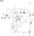
- Figure 2 A superheater 27 is provided, which is arranged between the heating surfaces 23 of the first evaporator 25 and the second evaporator 26. This offers the advantage that the gas turbine 2 can always be started up with the full gradient, even if the heat recovery steam generator 4 is depressurized and the superheater 27 is still dry, and thus uncooled.
- Figure 3 is based on the inventive design according to Figure 1 .
- Figure 3 shows a further development of the device according to the invention with separate preheaters 30, which are connected to taps on the steam turbine 11.
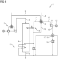
- Figure 4 is largely based on Figure 1 .
- Figure 4 shows a further development of the device according to the invention with a Once-through steam generator 16 and a desuperheater 17.
- the desuperheater 17 is designed as a heat exchanger 18, which is connected on the primary side to the steam line 10 between the steam turbine 11 and a condenser 24 downstream of the steam turbine 11 for energy absorption, and on the secondary side to the line 19 for supplying feedwater from the heat recovery steam generator 4 to the H 2 -O 2 reactor 6 for heat release.
Landscapes
- Engineering & Computer Science (AREA)
- Chemical & Material Sciences (AREA)
- Combustion & Propulsion (AREA)
- Mechanical Engineering (AREA)
- General Engineering & Computer Science (AREA)
- Life Sciences & Earth Sciences (AREA)
- Sustainable Development (AREA)
- Sustainable Energy (AREA)
- Physics & Mathematics (AREA)
- Thermal Sciences (AREA)
- Engine Equipment That Uses Special Cycles (AREA)
Claims (12)
- Installation (1) de production d'énergie électrique à partir d'hydrogène et d'oxygène, comprenant une machine (2) à combustion interne, en particulier une turbine à gaz, un générateur (4) de vapeur à récupération de la chaleur perdue monté dans le conduit (3) de gaz d'échappement de la machine (2) à combustion interne, dans laquelle le générateur (4) de vapeur à récupération de la chaleur perdue a seulement un étage (5) de pression, une turbine (11) à vapeur, un générateur (12) raccordé à la turbine (11) à vapeur et un conduit (19), caractérisée en ce qu'il est prévu en outre un réacteur (6) H2-O2, auquel de la vapeur (7) provenant du générateur (4) de vapeur à récupération de la chaleur perdue, de l'eau (31), de l'oxygène (8) et de l'hydrogène (9) peuvent être envoyés, de sorte qu'il peut être obtenu dans le réacteur (6) H2-O2, avec envoi de vapeur (7), une réaction de l'oxygène (8) et de l'hydrogène (9) en de la vapeur (10) d'eau, dans laquelle l'eau (31) engagée s'évapore, de la vapeur d'eau supplémentaire pouvant être produite, dans laquelle la vapeur (10) d'eau, fortement surchauffée en résultant, peut être envoyée à la turbine (11) à vapeur et, par le générateur (12) raccordé à la turbine (11) à vapeur, une puissance électrique peut être mise à disposition, dans laquelle, pour la commande ciblée de la réaction dans le réacteur (6) H2-O2 et pour le réglage de la température de sortie de la vapeur du réacteur H2-O2, de l'eau (14) d'alimentation sous haute pression peut être injectée du générateur (4) de vapeur à récupération de la chaleur perdue dans le réacteur (6) H2-O2 en passant par le conduit (19).
- Installation (1) suivant la revendication 1, caractérisée en ce qu'il est prévu en outre un désurchauffeur (17), qui est constitué en échangeur de chaleur (18), lequel est monté du côté primaire dans le conduit (10) pour la vapeur entre la turbine (11) à vapeur et un condenseur (24) en aval de la turbine (11) à vapeur et qui est monté du côté secondaire dans le conduit (19).
- Installation (1) suivant l'une des revendications précédentes, caractérisée en ce qu'il est prévu en outre un préchauffeur (20) de condensat, qui est monté en amont du générateur (4) de vapeur à récupération de la chaleur perdue pour le préchauffage de l'eau (13) d'alimentation, dans laquelle, pour augmenter le rendement, de la vapeur d'eau peut être prélevée d'une ou de plusieurs prises (21) sur la turbine (11) à vapeur et être envoyée au préchauffeur (20) de condensat.
- Installation (1) suivant l'une des revendications précédentes, caractérisée en ce que la pression d'évaporation dans le générateur (4) de vapeur à récupération de la chaleur perdue est réglée seulement si haute que, en fonction de la température de la vapeur vive réglée par la réaction H2-O2, on évite, même sans surchauffe intermédiaire, de l'humidité à la sortie de la turbine (11) à vapeur.
- Installation (1) suivant l'une des revendications précédentes, caractérisée en ce qu'il est prévu en outre un surchauffeur (22) fonctionnant électriquement, qui est monté en amont du réacteur (6) H2-O2 et par lequel la température de vapeur vive de la vapeur peut, lorsque le réacteur H2-O2 n'est pas en fonctionnement, être élevée tant que la présence d'humidité à la sortie de la turbine (11) à vapeur est empêchée.
- Installation suivant l'une des revendications précédentes, caractérisée en ce que le générateur (4) de vapeur à récupération de la chaleur perdue a des surfaces (23) de chauffe, qui forment un premier évaporateur (25) et un deuxième évaporateur (26) et des surfaces (23) de chauffe, qui forment un premier surchauffeur (27), dans laquelle le premier surchauffeur (27) est monté entre les surfaces (23) de chauffe du premier évaporateur (25) et du deuxième évaporateur (26), de manière à empêcher un retard potentiel au démarrage de la turbine (2) à gaz.
- Procédé de production d'énergie électrique à partir d'hydrogène et d'oxygène, comprenant une machine (2) à combustion interne, en particulier une turbine à gaz, un générateur (4) de vapeur à récupération de la chaleur perdue monté dans le conduit (3) de gaz d'échappement de la machine (2) à combustion interne, qui n'a qu'un étage (5) de pression, une turbine (11) à vapeur, un générateur (12) raccordé à la turbine à vapeur et un conduit (19),
dans lequel il est prévu en outre un réacteur (6) H2-O2, auquel on envoie de la vapeur (7) provenant du générateur (4) de vapeur à récupération de la chaleur perdue, de l'eau (31), de l'oxygène (8) et de l'hydrogène (9), de sorte que dans le réacteur (6) H2-O2, de l'oxygène (8) et de l'hydrogène (9) réagissent en donnant de la vapeur (10) d'eau, et davantage de vapeur d'eau se crée par l'évaporation de l'eau (31) injectée, dans lequel on envoie la vapeur d'eau à la turbine (11) à vapeur et, par le générateur (12) raccordé à la turbine (11) à vapeur, on produit une puissance électrique et on commande de manière ciblée la réaction dans le réacteur (6) H2-O2 et la température de la vapeur à la sortie du réacteur (6) H2-O2 en injectant comme eau (31) de l'eau (14) d'alimentation sous haute pression du générateur (4) de vapeur à récupération de la chaleur perdue dans le réacteur (6) H2-O2 en passant par le conduit (19). - Procédé suivant la revendication 7, dans lequel le circuit de vapeur d'eau comprend un désurchauffeur (17), qui est constitué en échangeur de chaleur (18), que l'on monte du côté primaire dans le conduit pour la vapeur de la turbine (11) à vapeur, et un condenseur (24) monté en aval de la turbine (11) à vapeur, afin d'absorber de la chaleur et que l'on monte du côté secondaire dans le conduit (13), pour céder de la chaleur.
- Procédé suivant l'une des revendications 7 ou 8, comprenant en outre un préchauffeur (20) de condensat, qui est monté en amont du générateur (4) de vapeur à récupération de la chaleur perdue et que l'on préchauffe par l'eau (13) d'alimentation, dans lequel pour augmenter le rendement on prélève de la vapeur d'eau d'une ou de plusieurs prises (21) sur la turbine (11) à vapeur et on l'envoie au préchauffeur (20) de condensat.
- Procédé suivant l'une des revendications 7 à 9, dans lequel la pression d'évaporation dans le générateur (4) de vapeur à récupération de la chaleur perdue est réglée seulement si haute que, en fonction de la température de la vapeur vive réglée par la réaction H2-O2, on évite, même sans surchauffe intermédiaire, de l'humidité à la sortie de la turbine (11) à vapeur.
- Procédé suivant l'une des revendications 7 à 10, comprenant en outre un surchauffeur (22) fonctionnant électriquement, qui est monté en amont du réacteur (6) H2-O2 et par lequel la température de vapeur vive de la vapeur peut, alors que le surchauffeur (22) ne fonctionne pas, être tant élevée que la présence d'humidité à la sortie de la turbine (11) à vapeur est empêchée.
- Procédé suivant l'une des revendications 7 à 11, dans lequel le générateur (4) de vapeur à récupération de la chaleur perdue a des surfaces de chauffe, qui forment un premier évaporateur (25) et un deuxième évaporateur (26), et des surfaces (23) de chauffe, qui forment un premier surchauffeur (27), dans laquelle le premier surchauffeur (27) est monté entre les surfaces (23) de chauffe du premier évaporateur (25) et du deuxième évaporateur (26), de manière à empêcher un retard potentiel au démarrage de la turbine (2) à gaz.
Applications Claiming Priority (2)
| Application Number | Priority Date | Filing Date | Title |
|---|---|---|---|
| DE102021203730.5A DE102021203730A1 (de) | 2021-04-15 | 2021-04-15 | Erzeugung von elektrischer Energie aus Wasserstoff und Sauerstoff |
| PCT/EP2022/059372 WO2022218841A1 (fr) | 2021-04-15 | 2022-04-08 | Production d'énergie électrique à partir d'hydrogène et d'oxygène |
Publications (2)
| Publication Number | Publication Date |
|---|---|
| EP4288643A1 EP4288643A1 (fr) | 2023-12-13 |
| EP4288643B1 true EP4288643B1 (fr) | 2025-06-04 |
Family
ID=81585444
Family Applications (1)
| Application Number | Title | Priority Date | Filing Date |
|---|---|---|---|
| EP22721711.4A Active EP4288643B1 (fr) | 2021-04-15 | 2022-04-08 | Production d'énergie électrique à partir d'hydrogène et d'oxygène |
Country Status (7)
| Country | Link |
|---|---|
| US (1) | US12595761B2 (fr) |
| EP (1) | EP4288643B1 (fr) |
| JP (1) | JP7728882B2 (fr) |
| KR (1) | KR102933714B1 (fr) |
| DE (1) | DE102021203730A1 (fr) |
| ES (1) | ES3040391T3 (fr) |
| WO (1) | WO2022218841A1 (fr) |
Family Cites Families (19)
| Publication number | Priority date | Publication date | Assignee | Title |
|---|---|---|---|---|
| US3101592A (en) * | 1961-01-16 | 1963-08-27 | Thompson Ramo Wooldridge Inc | Closed power generating system |
| US4148185A (en) | 1977-08-15 | 1979-04-10 | Westinghouse Electric Corp. | Double reheat hydrogen/oxygen combustion turbine system |
| DE4409196A1 (de) | 1994-03-17 | 1995-09-21 | Siemens Ag | Verfahren zum Betreiben einer Gas- und Dampfturbinenanlage sowie danach arbeitende Anlage |
| DE4409567A1 (de) * | 1994-03-21 | 1995-09-28 | Abb Management Ag | Verfahren zur Kühlung von thermisch belasteten Komponenten einer Gasturbogruppe |
| DE4480944T1 (de) | 1994-05-31 | 1997-07-24 | Mitsubishi Heavy Ind Ltd | Knallgas-Verbrennungsturbinenanlage |
| US5782081A (en) * | 1994-05-31 | 1998-07-21 | Pyong Sik Pak | Hydrogen-oxygen burning turbine plant |
| KR19990087240A (ko) * | 1996-02-26 | 1999-12-15 | 드폴 루이스 에이 | 수소 연료식 발전소에서 회전 축동력을 발생시키는 방법 |
| US5953900A (en) * | 1996-09-19 | 1999-09-21 | Siemens Westinghouse Power Corporation | Closed loop steam cooled steam turbine |
| JP3890104B2 (ja) * | 1997-01-31 | 2007-03-07 | 株式会社東芝 | コンバインドサイクル発電プラントおよびその冷却用蒸気供給方法 |
| US6230480B1 (en) * | 1998-08-31 | 2001-05-15 | Rollins, Iii William Scott | High power density combined cycle power plant |
| US8424281B2 (en) * | 2007-08-29 | 2013-04-23 | General Electric Company | Method and apparatus for facilitating cooling of a steam turbine component |
| EP2199547A1 (fr) | 2008-12-19 | 2010-06-23 | Siemens Aktiengesellschaft | Générateur de vapeur pour récupérer la chaleur et procédé de fonctionnement amélioré d'un générateur de vapeur pour récupérer la chaleur |
| DE102010035487A1 (de) | 2010-07-29 | 2012-02-23 | Linde Ag | Verfahren und Vorrichtung zur Stromspeicherung |
| DE102011121341A1 (de) | 2011-12-19 | 2013-06-20 | RERUM COGNITIO Institut GmbH | Dampfkraftprozess mit schnellaktivierbarer Leistungsreserve für die Elektroenergieerzeugung im Kreisprozess |
| DE102015209812A1 (de) | 2015-05-28 | 2016-12-01 | Siemens Aktiengesellschaft | Wasser-Dampf-Kreislauf einer Gas- und Dampfturbinenanlage |
| CN105134318B (zh) | 2015-08-07 | 2017-03-08 | 上海交通大学 | 基于氢气‑蒸汽涡轮复合循环的储能装置 |
| JP6783160B2 (ja) | 2017-02-03 | 2020-11-11 | 川崎重工業株式会社 | 水素酸素当量燃焼タービンシステム |
| CN211119284U (zh) * | 2019-08-13 | 2020-07-28 | 北京赫普电力科技有限公司 | 一种火电厂电启动蒸汽锅炉及电过热器系统 |
| US12092021B2 (en) * | 2020-02-10 | 2024-09-17 | Tascosa Advanced Services, Inc. | Hydrogen hybrid cycle system |
-
2021
- 2021-04-15 DE DE102021203730.5A patent/DE102021203730A1/de not_active Ceased
-
2022
- 2022-04-08 KR KR1020237038820A patent/KR102933714B1/ko active Active
- 2022-04-08 EP EP22721711.4A patent/EP4288643B1/fr active Active
- 2022-04-08 WO PCT/EP2022/059372 patent/WO2022218841A1/fr not_active Ceased
- 2022-04-08 US US18/286,126 patent/US12595761B2/en active Active
- 2022-04-08 ES ES22721711T patent/ES3040391T3/es active Active
- 2022-04-08 JP JP2023561260A patent/JP7728882B2/ja active Active
Also Published As
| Publication number | Publication date |
|---|---|
| KR20230169286A (ko) | 2023-12-15 |
| WO2022218841A1 (fr) | 2022-10-20 |
| ES3040391T3 (en) | 2025-10-30 |
| KR102933714B1 (ko) | 2026-03-05 |
| US20240200472A1 (en) | 2024-06-20 |
| JP2024513438A (ja) | 2024-03-25 |
| US12595761B2 (en) | 2026-04-07 |
| EP4288643A1 (fr) | 2023-12-13 |
| JP7728882B2 (ja) | 2025-08-25 |
| DE102021203730A1 (de) | 2022-10-20 |
Similar Documents
| Publication | Publication Date | Title |
|---|---|---|
| EP0518868B1 (fr) | Procede et installation pour la production d'energie mecanique | |
| DE60033889T2 (de) | Verfahren zur Energieerzeugung mit einem thermochemischen Rückgewinnungskreislauf | |
| EP2199547A1 (fr) | Générateur de vapeur pour récupérer la chaleur et procédé de fonctionnement amélioré d'un générateur de vapeur pour récupérer la chaleur | |
| CH678987A5 (fr) | ||
| DE102018201172A1 (de) | Verbrennungsanlage mit Restwärmenutzung | |
| WO2000020728A1 (fr) | Installation a turbine a gaz et a vapeur | |
| EP2423465A2 (fr) | Procédé de fonctionnement d'une centrale à turbine à vapeur et dispositif de production de vapeur | |
| EP1910740B1 (fr) | Procede et dispositif de production de vapeur surchauffee | |
| EP1099042B1 (fr) | Installation a turbine a gaz et a vapeur | |
| EP3810907B1 (fr) | Recirculation des gaz d'échappement dans des installations de turbines à gaz et à vapeur | |
| DE19627425A1 (de) | Verfahren zum Betrieb einer Hybrid-Solar-Kombianlage sowie eine Hybrid-Solar-Kombianlage | |
| EP2480763B1 (fr) | Centrale à vapeur | |
| WO2004003348A1 (fr) | Centrale a vapeur | |
| EP1584798B1 (fr) | Méthode et appareil pour la production d'électricité et de chaleur | |
| DE19962403A1 (de) | Verfahren zum Umrüsten eines Sattdampf erzeugenden Systems mit mindestens einer Dampfturbogruppe sowie nach dem Verfahren umgerüstetes Kraftwerk | |
| DE102021203730A1 (de) | Erzeugung von elektrischer Energie aus Wasserstoff und Sauerstoff | |
| DE20313279U1 (de) | Dampfkraftwerk | |
| EP2559867A1 (fr) | Procédé de production d'énergie électrique à l'aide d'une centrale électrique combinée et centrale électrique combinée destinée à l'exécution du procédé | |
| DE102007014631A1 (de) | Energiegewinnung in einer mit Gasturbine gekoppelten Verbrennungsanlage | |
| CH718340A2 (de) | Steigerung der Leistung von Gas- und Dampfturbinenanlagen bei einer neuen Zusatzvorfeuerung. | |
| EP1404947B1 (fr) | Procede pour faire fonctionner une installation motrice a vapeur et installation motrice a vapeur pour mettre en oeuvre ce procede | |
| EP0379108A1 (fr) | Procédé de production d'énergie électrique dans un cycle combiné gaz-vapeur et installation de gazéification de combustible | |
| EP1242729B1 (fr) | Procede permettant de faire fonctionner une turbine a vapeur, ainsi qu'ensemble turbine dote d'une turbine a vapeur fonctionnant selon ledit procede | |
| DE2302440C2 (de) | Verfahren zur Spaltung von Kohlenwasserstoffen bei hohen Temperaturen unter Verwendung von Prozeßdampf | |
| EP4062037A1 (fr) | Installation de récupération de chaleur perdue pour l'utilisation d'énergie thermique récupérée à partir de flux de gaz d'échappement pour la production d'énergie au moyen de vapeur |
Legal Events
| Date | Code | Title | Description |
|---|---|---|---|
| STAA | Information on the status of an ep patent application or granted ep patent |
Free format text: STATUS: UNKNOWN |
|
| STAA | Information on the status of an ep patent application or granted ep patent |
Free format text: STATUS: THE INTERNATIONAL PUBLICATION HAS BEEN MADE |
|
| PUAI | Public reference made under article 153(3) epc to a published international application that has entered the european phase |
Free format text: ORIGINAL CODE: 0009012 |
|
| STAA | Information on the status of an ep patent application or granted ep patent |
Free format text: STATUS: REQUEST FOR EXAMINATION WAS MADE |
|
| 17P | Request for examination filed |
Effective date: 20230906 |
|
| AK | Designated contracting states |
Kind code of ref document: A1 Designated state(s): AL AT BE BG CH CY CZ DE DK EE ES FI FR GB GR HR HU IE IS IT LI LT LU LV MC MK MT NL NO PL PT RO RS SE SI SK SM TR |
|
| DAV | Request for validation of the european patent (deleted) | ||
| DAX | Request for extension of the european patent (deleted) | ||
| GRAP | Despatch of communication of intention to grant a patent |
Free format text: ORIGINAL CODE: EPIDOSNIGR1 |
|
| STAA | Information on the status of an ep patent application or granted ep patent |
Free format text: STATUS: GRANT OF PATENT IS INTENDED |
|
| INTG | Intention to grant announced |
Effective date: 20241111 |
|
| RAP3 | Party data changed (applicant data changed or rights of an application transferred) |
Owner name: SIEMENS ENERGY GLOBAL GMBH & CO. KG |
|
| GRAS | Grant fee paid |
Free format text: ORIGINAL CODE: EPIDOSNIGR3 |
|
| GRAA | (expected) grant |
Free format text: ORIGINAL CODE: 0009210 |
|
| STAA | Information on the status of an ep patent application or granted ep patent |
Free format text: STATUS: THE PATENT HAS BEEN GRANTED |
|
| AK | Designated contracting states |
Kind code of ref document: B1 Designated state(s): AL AT BE BG CH CY CZ DE DK EE ES FI FR GB GR HR HU IE IS IT LI LT LU LV MC MK MT NL NO PL PT RO RS SE SI SK SM TR |
|
| REG | Reference to a national code |
Ref country code: GB Ref legal event code: FG4D Free format text: NOT ENGLISH |
|
| REG | Reference to a national code |
Ref country code: CH Ref legal event code: EP |
|
| REG | Reference to a national code |
Ref country code: DE Ref legal event code: R081 Ref document number: 502022004164 Country of ref document: DE Owner name: SIEMENS ENERGY GLOBAL GMBH & CO. KG, DE Free format text: FORMER OWNER: ANMELDERANGABEN UNKLAR / UNVOLLSTAENDIG, 80297 MUENCHEN, DE |
|
| REG | Reference to a national code |
Ref country code: DE Ref legal event code: R096 Ref document number: 502022004164 Country of ref document: DE |
|
| REG | Reference to a national code |
Ref country code: IE Ref legal event code: FG4D Free format text: LANGUAGE OF EP DOCUMENT: GERMAN |
|
| RAP4 | Party data changed (patent owner data changed or rights of a patent transferred) |
Owner name: SIEMENS ENERGY GLOBAL GMBH & CO. KG |
|
| REG | Reference to a national code |
Ref country code: NL Ref legal event code: FP |
|
| PG25 | Lapsed in a contracting state [announced via postgrant information from national office to epo] |
Ref country code: FI Free format text: LAPSE BECAUSE OF FAILURE TO SUBMIT A TRANSLATION OF THE DESCRIPTION OR TO PAY THE FEE WITHIN THE PRESCRIBED TIME-LIMIT Effective date: 20250604 |
|
| REG | Reference to a national code |
Ref country code: LT Ref legal event code: MG9D |
|
| PG25 | Lapsed in a contracting state [announced via postgrant information from national office to epo] |
Ref country code: NO Free format text: LAPSE BECAUSE OF FAILURE TO SUBMIT A TRANSLATION OF THE DESCRIPTION OR TO PAY THE FEE WITHIN THE PRESCRIBED TIME-LIMIT Effective date: 20250904 Ref country code: GR Free format text: LAPSE BECAUSE OF FAILURE TO SUBMIT A TRANSLATION OF THE DESCRIPTION OR TO PAY THE FEE WITHIN THE PRESCRIBED TIME-LIMIT Effective date: 20250905 |
|
| PG25 | Lapsed in a contracting state [announced via postgrant information from national office to epo] |
Ref country code: PL Free format text: LAPSE BECAUSE OF FAILURE TO SUBMIT A TRANSLATION OF THE DESCRIPTION OR TO PAY THE FEE WITHIN THE PRESCRIBED TIME-LIMIT Effective date: 20250604 |
|
| PG25 | Lapsed in a contracting state [announced via postgrant information from national office to epo] |
Ref country code: BG Free format text: LAPSE BECAUSE OF FAILURE TO SUBMIT A TRANSLATION OF THE DESCRIPTION OR TO PAY THE FEE WITHIN THE PRESCRIBED TIME-LIMIT Effective date: 20250604 |
|
| PG25 | Lapsed in a contracting state [announced via postgrant information from national office to epo] |
Ref country code: HR Free format text: LAPSE BECAUSE OF FAILURE TO SUBMIT A TRANSLATION OF THE DESCRIPTION OR TO PAY THE FEE WITHIN THE PRESCRIBED TIME-LIMIT Effective date: 20250604 |
|
| PG25 | Lapsed in a contracting state [announced via postgrant information from national office to epo] |
Ref country code: RS Free format text: LAPSE BECAUSE OF FAILURE TO SUBMIT A TRANSLATION OF THE DESCRIPTION OR TO PAY THE FEE WITHIN THE PRESCRIBED TIME-LIMIT Effective date: 20250904 |
|
| PG25 | Lapsed in a contracting state [announced via postgrant information from national office to epo] |
Ref country code: LV Free format text: LAPSE BECAUSE OF FAILURE TO SUBMIT A TRANSLATION OF THE DESCRIPTION OR TO PAY THE FEE WITHIN THE PRESCRIBED TIME-LIMIT Effective date: 20250604 |
|
| REG | Reference to a national code |
Ref country code: ES Ref legal event code: FG2A Ref document number: 3040391 Country of ref document: ES Kind code of ref document: T3 Effective date: 20251030 |
|
| PG25 | Lapsed in a contracting state [announced via postgrant information from national office to epo] |
Ref country code: PT Free format text: LAPSE BECAUSE OF FAILURE TO SUBMIT A TRANSLATION OF THE DESCRIPTION OR TO PAY THE FEE WITHIN THE PRESCRIBED TIME-LIMIT Effective date: 20251006 |
|
| PG25 | Lapsed in a contracting state [announced via postgrant information from national office to epo] |
Ref country code: IS Free format text: LAPSE BECAUSE OF FAILURE TO SUBMIT A TRANSLATION OF THE DESCRIPTION OR TO PAY THE FEE WITHIN THE PRESCRIBED TIME-LIMIT Effective date: 20251004 |
|
| PG25 | Lapsed in a contracting state [announced via postgrant information from national office to epo] |
Ref country code: SM Free format text: LAPSE BECAUSE OF FAILURE TO SUBMIT A TRANSLATION OF THE DESCRIPTION OR TO PAY THE FEE WITHIN THE PRESCRIBED TIME-LIMIT Effective date: 20250604 |
|
| PG25 | Lapsed in a contracting state [announced via postgrant information from national office to epo] |
Ref country code: CZ Free format text: LAPSE BECAUSE OF FAILURE TO SUBMIT A TRANSLATION OF THE DESCRIPTION OR TO PAY THE FEE WITHIN THE PRESCRIBED TIME-LIMIT Effective date: 20250604 |
|
| PG25 | Lapsed in a contracting state [announced via postgrant information from national office to epo] |
Ref country code: EE Free format text: LAPSE BECAUSE OF FAILURE TO SUBMIT A TRANSLATION OF THE DESCRIPTION OR TO PAY THE FEE WITHIN THE PRESCRIBED TIME-LIMIT Effective date: 20250604 |
|
| PG25 | Lapsed in a contracting state [announced via postgrant information from national office to epo] |
Ref country code: SK Free format text: LAPSE BECAUSE OF FAILURE TO SUBMIT A TRANSLATION OF THE DESCRIPTION OR TO PAY THE FEE WITHIN THE PRESCRIBED TIME-LIMIT Effective date: 20250604 |
|
| REG | Reference to a national code |
Ref country code: DE Ref legal event code: R097 Ref document number: 502022004164 Country of ref document: DE |
|
| PGFP | Annual fee paid to national office [announced via postgrant information from national office to epo] |
Ref country code: GB Payment date: 20260323 Year of fee payment: 5 |
|
| PLBE | No opposition filed within time limit |
Free format text: ORIGINAL CODE: 0009261 |
|
| STAA | Information on the status of an ep patent application or granted ep patent |
Free format text: STATUS: NO OPPOSITION FILED WITHIN TIME LIMIT |
|
| PG25 | Lapsed in a contracting state [announced via postgrant information from national office to epo] |
Ref country code: DK Free format text: LAPSE BECAUSE OF FAILURE TO SUBMIT A TRANSLATION OF THE DESCRIPTION OR TO PAY THE FEE WITHIN THE PRESCRIBED TIME-LIMIT Effective date: 20250604 |
|
| REG | Reference to a national code |
Ref country code: CH Ref legal event code: L10 Free format text: ST27 STATUS EVENT CODE: U-0-0-L10-L00 (AS PROVIDED BY THE NATIONAL OFFICE) Effective date: 20260416 |
|
| 26N | No opposition filed |
Effective date: 20260305 |