EP4289252A2 - Moissonneuse-batteuse avec système d'assistance au conducteur comprenant un assistant d'étalonnage pour un capteur de perte de grain - Google Patents
Moissonneuse-batteuse avec système d'assistance au conducteur comprenant un assistant d'étalonnage pour un capteur de perte de grain Download PDFInfo
- Publication number
- EP4289252A2 EP4289252A2 EP23168767.4A EP23168767A EP4289252A2 EP 4289252 A2 EP4289252 A2 EP 4289252A2 EP 23168767 A EP23168767 A EP 23168767A EP 4289252 A2 EP4289252 A2 EP 4289252A2
- Authority
- EP
- European Patent Office
- Prior art keywords
- grain loss
- loss sensor
- combine harvester
- grain
- dialog
- Prior art date
- Legal status (The legal status is an assumption and is not a legal conclusion. Google has not performed a legal analysis and makes no representation as to the accuracy of the status listed.)
- Pending
Links
Images

Classifications
-
- A—HUMAN NECESSITIES
- A01—AGRICULTURE; FORESTRY; ANIMAL HUSBANDRY; HUNTING; TRAPPING; FISHING
- A01D—HARVESTING; MOWING
- A01D41/00—Combines, i.e. harvesters or mowers combined with threshing devices
- A01D41/12—Details of combines
- A01D41/127—Control or measuring arrangements specially adapted for combines
- A01D41/1271—Control or measuring arrangements specially adapted for combines for measuring crop flow
- A01D41/1272—Control or measuring arrangements specially adapted for combines for measuring crop flow for measuring grain flow
- A01D41/1273—Control or measuring arrangements specially adapted for combines for measuring crop flow for measuring grain flow for measuring grain loss
-
- A—HUMAN NECESSITIES
- A01—AGRICULTURE; FORESTRY; ANIMAL HUSBANDRY; HUNTING; TRAPPING; FISHING
- A01D—HARVESTING; MOWING
- A01D41/00—Combines, i.e. harvesters or mowers combined with threshing devices
- A01D41/12—Details of combines
- A01D41/127—Control or measuring arrangements specially adapted for combines
- A01D41/1276—Control or measuring arrangements specially adapted for combines for cleaning mechanisms
Definitions
- the grain losses that occur are those grains of the harvested crop stream that have either not been effectively threshed out of the straw in the first place or have not been able to continue to grow in despite being threshed by the threshing device, also known as the threshing mechanism, or by the cleaning device of the combine harvester - as actually desired the grain tank, but, like the threshed straw, is left on the field by the combine harvester.
- These grain losses which should be kept as small as possible, depend on the one hand on the driving speed and the operating settings, in particular of the threshing device of the combine harvester, and on the other hand on environmental conditions such as the condition of the crop and the field, e.g. B. in terms of moisture and crop density. There are therefore no unchangeable and optimal settings for the threshing device for all boundary conditions, rather these must be adjusted to reduce or minimize grain losses according to the above environmental conditions and the driving speed.
- Such a grain loss test dish is, for example, from the DE 198 20 819 C2 known.
- the problem with grain loss sensors is that it is difficult to establish a relationship between the values measured by the grain loss sensor and the actual grain losses.
- the relationship between the values measured by the grain loss sensor which are referred to here and below as sensor values of the grain loss sensor and refer to the measurement signal generated by the grain loss sensor as such - with the actual grain losses also depends very much on the total crop flow volume as well as on the above-mentioned environmental conditions.
- a so-called calibration of the grain loss sensors i.e. determining and adjusting a grain loss sensor sensitivity, is therefore absolutely necessary in order to establish the aforementioned relationship between the values measured by the grain loss sensor and the actual grain losses, which are determined, for example, using a previously mentioned grain loss test pan.
- carrying out such a calibration is very complex.
- Another advantage is that the combine harvester operator is involved in the investigation and adjustment process thanks to the dialogue-based approach. This allows the operator, whether an inexperienced operator or an experienced operator, to gain important experience that will enable him to make adjustments to the work parameters and machine settings in future crop processing operations.
- the grain loss sensor setting assistant determines the grain loss sensor sensitivity in the dialog, taking into account retrievable and/or specifiable data or parameters relating to the combine harvester and/or a crop processing process.
- the dialog of the grain loss sensor setting assistant thus ensures that the operator only has to make necessary settings or only have to transfer necessary data or parameters and/or accept settings suggested by the system directly, i.e. without further input, i.e. confirm them , can.
- the dialog of the grain loss sensor setting assistant includes a dialog step A, in which it is checked whether the operating states of the combine harvester required for determining and adjusting the grain loss sensor sensitivity are present.
- dialog step A it is checked whether the combine harvester is in a crop processing process and / or the crop processing process is carried out by the combine harvester under stationary conditions.
- dialog step A if it is determined that the combine harvester is not in a crop processing process and/or the crop processing process by the combine harvester is not taking place under stationary conditions, the operator receives an instruction for controlling the combine harvester.
- dialog step D the operator carries out a measurement to determine grain losses of the separating device and/or the cleaning device and optionally triggers a measurement for determining a yield of the combine harvester, whereby a sensor value of the at least one grain loss sensor of the separation device and / or a sensor value of the at least one grain loss sensor of the cleaning device and optionally a sensor value of a sensor for determining the yield of the combine harvester is determined over a specified measurement period .
- dialog step D the operator receives an instruction to trigger the measurement for determining grain losses of the separating device and/or the cleaning device and optionally the measurement for determining the yield of the combine harvester essentially at the same time as the placement of the grain loss test tray.
- the dialog of the grain loss sensor setting assistant includes a dialog step E, in which the operator selects a metric for entering an amount of lost grains determined using the grain loss test bowl, the operator enters the determined amount of lost grains and the actual grain losses are displayed to the operator.
- the dialog of the grain loss sensor setting assistant includes a dialog step F, in which the determined grain loss sensor sensitivity for the at least one grain loss sensor of the separation device and / or for the at least one grain loss sensor of the cleaning device is displayed to the operator and optionally the operator adjusts the grain loss sensor sensitivity displayed to him.
- the dialog of the grain loss sensor setting assistant includes a dialog step G, in which the operator confirms the grain loss sensor sensitivity displayed to him and optionally adjusted, whereby the grain loss sensor sensitivity for the at least one grain loss sensor of the separating device and / or for the at least one grain loss sensor of the Cleaning device is set or rejected.
- the operator thus receives information about which grain loss sensor sensitivity is recommended for setting, but also has the opportunity to change or manipulate this according to his wishes and experience. By simply confirming the recommendation, it can be applied immediately to the corresponding grain loss sensor.
- the object according to the invention is achieved by a method for determining and adjusting a grain loss sensor sensitivity of at least one grain loss sensor of such a combine harvester according to independent claim 15.
- FIG. 1 a harvesting machine 1 designed as a combine harvester 2 is shown in a schematic and exemplary representation.
- the combine harvester 2 has an attachment 3 which is designed as a cutting unit and is attached or adapted to the combine harvester 2, an inclined conveyor 4, a threshing device 5, also called a threshing unit, a separating device 6, a cleaning device 7, a transport device 8, a grain tank 9 and a distribution device 10 on, all of which are also referred to as working units of the combine harvester 2 for carrying out a crop processing process.
- the grain components are to be separated from the non-grain components, i.e. the crop in other respects, with the separated grain components being cleaned from the non-grain components in the cleaning device 7 and then the thus cleaned grain components by means of the transport device 8 be fed to the grain tank 9.
- the non-grain components such as the straw and the chaff, are then deposited at the rear of the combine harvester 2 by the distribution device 10 on the ground or the agricultural area 12, which is processed by the combine harvester, or appear at the corresponding end of the separating device 6, which can include longitudinally aligned shaker hordes or separator rotors, from the combine harvester 2 and reach the ground or the agricultural area 12.
- the threshing device 5 In the threshing device 5, most of the grain components are separated from the harvested crop stream 11. The so-called residual grain and the non-grain components reach the separation device 6, where a further separation process takes place in order to largely separate the residual grain from the non-grain components in the crop stream 11.
- the crop mixture 13 of non-separated residual grain and non-grain components emerging from the separation device 6 at the end is returned to the ground or the agricultural area 12 by the distribution device 10, which comprises a straw chopper 14 and here and preferably a radial distributor 15.
- At least one grain loss sensor 17 which serves to detect the grain components emerging from the combine as crop losses 16.
- at least two grain loss sensors 17 are used, the positioning of which takes place in a known manner at the end of the separating device 6 and the cleaning device 7, i.e. in the delivery area of the crop stream 11, which essentially consists of non-grain components.
- both the separating device 6 and the cleaning device 7 each comprise at least one grain loss sensor 17.
- the grain loss sensors 17 only detect a proportion of the crop losses 16, since the grain loss sensors 17 cannot easily and directly detect the quantitatively precise amount of crop losses 16. This is not only because not all lost grains reach the detection range of the grain loss sensors 17 anyway, but also because the relationship between the grain losses measured by the grain loss sensors 17 and the actual amount of lost grains can be very different.
- the combine harvester 2 further comprises a driver assistance system 20, which has a memory for storing data or parameters, in particular data or parameters relating to the combine harvester 2 and / or a crop processing process or combine threshing process, a computing device for processing data that can be stored in the memory and / or stored data or parameters as well as an input/output unit 21, which is used to interact with the operator of the combine harvester 2.
- the driver assistance system 20 can include or be designed as a mobile terminal that communicates with the combine harvester 2, preferably wirelessly via a receiver/transmitter module 22. If the driver assistance system 20 includes a mobile terminal, individual or all of the previously mentioned devices, i.e. the memory, the computing device and/or the input/output unit 21, can be part of the mobile terminal.
- the term “calibration of the grain loss sensors” means determining and setting a grain loss sensor sensitivity of the grain loss sensors 17.
- the driver assistance system 20 comprises a grain loss sensor setting assistant 23.
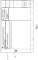
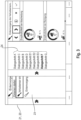
- This grain loss sensor setting assistant 23 is preferably an on the driver assistance system 20 running Software program. Such a grain loss sensor setting assistant 23 is exemplified in the FIGs. 2 and 3 pictured.
- steady conditions is to be understood in particular as meaning that essentially no fluctuations in the yield and/or throughput of the combine harvester 2, ie negligible fluctuations at all, occur during the crop processing process or combine threshing process and/or that sensors do not provide values that are outside of specified limit values during the crop processing or combine threshing process.
- dialog step A The check of the existence of required operating states of the combine harvester 2 carried out in dialog step A is preferably carried out automatically. Alternatively, it is also conceivable that the operator is asked in dialog step A to trigger this check. If it is determined during the test that the combine harvester 2 is not in the crop processing process or combine threshing process and / or the crop processing process or combine threshing by the combine harvester 2 is not carried out under stationary conditions, the operator receives an instruction for control in dialog step A of the combine harvester 2. This instruction enables the operator to control the combine harvester 2 in such a way that the operating states of the combine harvester 2 required or necessary for determining and adjusting the grain loss sensor sensitivity are present.
- the dialog of the grain loss sensor setting assistant 23 may include a dialog step B in which the operator enters a grain loss target to be achieved during the crop processing process.
- This grain loss target can be entered, for example, as a relative amount based on a size, for example a total grain volume or a total grain mass.
- dialog step B it is possible for the operator to enter a working width of the attachment 3 attached to the combine harvester 2. This input is to be seen as an option, since there is also the possibility that this size is automatically determined by the grain loss sensor setting assistant 23 and is viewed as given in dialog step B.
- the dialog of the grain loss sensor setting assistant 23 can further include a dialog step C in which the operator enters dimensions of one or the grain loss test tray 18.
- a grain loss test dish 18 is used to determine the actual grain losses. Since such grain loss test bowls 18 are generally rectangular, the operator preferably enters a length and a width of the grain loss test bowl 18 in dialog step C.
- the operator enters a storage position of the grain loss test tray 18, i.e. a position in the area of the rear of the combine harvester 2, at which the grain loss test tray 18 is to be placed. It is also possible to enter more than one storage position, preferably two storage positions, if more than one grain loss test tray 18 is to be used to determine the actual grain losses.
- the dialog of the grain loss sensor setting assistant 23 can also include a dialog step D in which the operator receives an instruction to initiate the storage of the grain loss test tray 18.
- a dialog step D in which the operator receives an instruction to initiate the storage of the grain loss test tray 18.
- the operator receives an instruction to initiate the storage of the grain loss test tray 18.
- a storage device 19 is provided for depositing the grain loss test tray 18 on the combine harvester 2
- the operator can initiate the automatic placement of the grain loss test tray 18 on the ground or the agricultural area 12 via the storage device 19, for example by pressing an actuating element. If such a storage device 19 is not provided on the combine harvester 2, but the grain loss test tray 18 must be placed manually, the operator of the combine harvester 2 can instruct another person to place the grain loss test tray 18 on the ground or the agricultural area 12.
- dialog step D the operator further triggers a measurement to determine grain losses of the separating device 6 and/or the cleaning device 7 and optionally, i.e. if a sensor for determining a yield of the combine harvester 2 is present, a measurement to determine the yield of the combine harvester 2 .
- a sensor value of the at least one grain loss sensor 17 of the separating device 6 and/or a sensor value of the at least a grain loss sensor 17 of the cleaning device 7 and optionally a sensor value of the sensor for determining the yield of the combine harvester 2 is determined.
- the operator further receives an instruction that the measurement for determining grain losses of the at least one grain loss sensor of the separating device 6 and/or the cleaning device 7 and optionally the measurement for determining the yield of the combine harvester 2 essentially at the same time, i.e. simultaneously or at least immediately successively, with the placement of the grain loss test bowl 18 to be triggered or initiated, so that the determination of grain losses and optionally the yield takes place essentially at the same location as the placement of the grain loss test bowl 18. This ensures that the sensors essentially detect the same part of the crop mixture 13 that is also collected by the grain loss test tray 18.
- the position of the combine harvester 2 during the measurement of the sensor values and the placement of the grain loss test tray is displayed in dialog step D 18 recorded and transmitted to the mobile terminal, preferably via the receiver/transmitter module 22.
- a yield of the combine harvester 2 can be estimated by the operator and entered in the dialog, preferably in dialog step B, so that the yield of the combine harvester 2 can be entered in such a way In this case, it can be available as a further or alternative option in dialog step B.
- the dialog of the grain loss sensor setting assistant 23 can include a dialog step E, which in turn can include a number of individual dialog steps E1 to E3.
- the dialog step E can include a dialog step E1 in which the operator selects a metric for entering a quantity of loss grains determined using the grain loss test tray 18. Such a metric can be either a number of loss grains determined, a mass of loss grains determined or a volume of loss grains determined. After selecting the metric, the operator enters the amount of loss grains determined using the grain loss test tray 18 in a dialog step E2 in accordance with the previously selected metric. After the number of lost grains has been entered by the operator in dialog step E1, a determined actual grain loss is displayed to him in a dialog step E3.
- This actual grain loss can also be displayed as a relative amount based on a quantity, for example a total grain volume or a total grain mass.
- the grain loss sensor setting assistant 23 in addition to the number of lost grains entered, preferably uses the yield determined during the measurement in dialog step D as well as the dimensions of the grain loss test tray 18 entered in dialog step B as well as the retrieved or entered working width of the attachment 3 back.
- the processes to be processed in dialog steps E1 to E3 can also be processed in one dialog step, i.e. dialog step E.
- the dialog of the grain loss sensor setting assistant 23 can include a dialog step F, which is exemplary FIG. 3 can be seen in which the determined grain loss sensor sensitivity for the at least one grain loss sensor 17 of the separating device 6 and / or for the at least one grain loss sensor 17 of the cleaning device 7 is displayed to the operator.
- the grain loss sensor setting assistant 23 preferably uses the data or parameters determined in dialog steps A to E and/or entered by the operator.
- the dialog step F also offers the operator the option of determining the determined grain loss sensor sensitivity of the at least a grain loss sensor 17 of the separating device 6 and / or the at least one grain loss sensor 17 of the cleaning device 7 can be subsequently adapted in accordance with his ideas and experience and deviating from the determined suggestion. This gives the operator the opportunity to manually manipulate or override the grain loss sensor sensitivity determined as part of the dialogue with the grain loss sensor setting assistant 23.
- the dialog of the grain loss sensor setting assistant 23 can further include a dialog step G in which the operator confirms or rejects the grain loss sensor sensitivity displayed to him and, if necessary, adjusted. If the operator confirms or accepts the grain loss sensor sensitivity displayed and, if necessary, adjusted, this is automatically adopted or set for the at least one grain loss sensor 17 of the separating device 6 and/or the at least one grain loss sensor 17 of the cleaning device 7. The operator therefore no longer has to manually adjust or set the sensor sensitivity of the corresponding grain loss sensor 17 in a process step following the dialog. If the operator rejects the grain loss sensor sensitivity displayed to him, the dialog for determining and setting the grain loss sensor sensitivity is ended.
- dialog steps 24 are not to be understood as restrictive with regard to further dialog steps in the dialog. Further dialog steps can be provided before, between and/or after the individual dialog steps 24 described above. Furthermore, the naming of the previously described dialog steps 24 with the letters “A to G” should not be understood to mean that these dialog steps are processed one after the other according to the order of the letters. Rather, naming using letters only serves to differentiate the individual dialogue steps from one another. For example, dialog step C can also take place before dialog step B, as is the case, for example FIG. 3 can be seen.
- the dialogue steps can be implemented in various ways. A dialog step can also include several dialog steps, other dialog steps can be processed between the individual dialog steps of a dialog step, and some dialog steps can also be processed multiple times if this is necessary.
- the placement of a grain loss test tray 18 and its evaluation can be dispensed with during a new calibration.
- a method for determining and adjusting a grain loss sensor sensitivity of at least one grain loss sensor 17 of such a combine harvester 2 is also provided within the scope of the invention .
- the method is correspondingly characterized in that the grain loss sensor sensitivity to be set for the at least one grain loss sensor 17 of the separating device 6 and/or the at least one grain loss sensor 17 of the cleaning device 7 is set in a dialogue with the grain loss sensor setting assistant 23 of the driver assistance system 20 of the combine harvester 2 Operator is determined in several dialog steps 24.
Landscapes
- Life Sciences & Earth Sciences (AREA)
- Environmental Sciences (AREA)
- Combines (AREA)
Applications Claiming Priority (1)
| Application Number | Priority Date | Filing Date | Title |
|---|---|---|---|
| DE102022114529.8A DE102022114529A1 (de) | 2022-06-09 | 2022-06-09 | Mähdrescher mit Fahrerassistenzsystem |
Publications (2)
| Publication Number | Publication Date |
|---|---|
| EP4289252A2 true EP4289252A2 (fr) | 2023-12-13 |
| EP4289252A3 EP4289252A3 (fr) | 2024-03-06 |
Family
ID=86095868
Family Applications (1)
| Application Number | Title | Priority Date | Filing Date |
|---|---|---|---|
| EP23168767.4A Pending EP4289252A3 (fr) | 2022-06-09 | 2023-04-19 | Moissonneuse-batteuse avec système d'assistance au conducteur comprenant un assistant d'étalonnage pour un capteur de perte de grain |
Country Status (3)
| Country | Link |
|---|---|
| US (1) | US20230397533A1 (fr) |
| EP (1) | EP4289252A3 (fr) |
| DE (1) | DE102022114529A1 (fr) |
Citations (3)
| Publication number | Priority date | Publication date | Assignee | Title |
|---|---|---|---|---|
| EP0339142B1 (fr) | 1988-04-26 | 1992-09-02 | Ford New Holland N.V. | Détecteurs d'impact |
| DE19820819C2 (de) | 1998-05-09 | 2003-02-20 | Andrea Kluesendorf-Feiffer | Vorrichtung und Verfahren zur Prozeßleittechnik in der Getreideernte - Verlustprüfschale |
| EP2742791A2 (fr) * | 2012-12-17 | 2014-06-18 | Deere & Company | Procédé et dispositif d'optimisation d'un paramètre de fonctionnement d'une moissonneuse-batteuse |
Family Cites Families (7)
| Publication number | Priority date | Publication date | Assignee | Title |
|---|---|---|---|---|
| EP0339141B1 (fr) * | 1988-04-26 | 1994-07-06 | New Holland Belgium N.V. | Procédé et appareil pour mesurer les pertes de grains dans des moissonneuses |
| DE102009009767A1 (de) * | 2009-02-20 | 2010-08-26 | Claas Selbstfahrende Erntemaschinen Gmbh | Fahrerassistenzsystem für landwirtschaftliche Arbeitsmaschine |
| US9699970B2 (en) * | 2013-09-19 | 2017-07-11 | Cnh Industrial America Llc | Combine side-shake cleaning control system |
| EP3125670B1 (fr) * | 2014-04-01 | 2019-01-23 | The Climate Corporation | Procédés de surveillance d'opérateur de machine agricole |
| US10209235B2 (en) * | 2015-05-04 | 2019-02-19 | Deere & Company | Sensing and surfacing of crop loss data |
| BE1022889B1 (nl) * | 2015-05-29 | 2016-10-07 | Cnh Industrial Belgium Nv | controller voor een oogstmachine |
| US11723308B2 (en) * | 2019-01-31 | 2023-08-15 | Cnh Industrial America Llc | Combine loss monitor mapping |
-
2022
- 2022-06-09 DE DE102022114529.8A patent/DE102022114529A1/de active Pending
-
2023
- 2023-04-19 EP EP23168767.4A patent/EP4289252A3/fr active Pending
- 2023-06-08 US US18/207,449 patent/US20230397533A1/en active Pending
Patent Citations (3)
| Publication number | Priority date | Publication date | Assignee | Title |
|---|---|---|---|---|
| EP0339142B1 (fr) | 1988-04-26 | 1992-09-02 | Ford New Holland N.V. | Détecteurs d'impact |
| DE19820819C2 (de) | 1998-05-09 | 2003-02-20 | Andrea Kluesendorf-Feiffer | Vorrichtung und Verfahren zur Prozeßleittechnik in der Getreideernte - Verlustprüfschale |
| EP2742791A2 (fr) * | 2012-12-17 | 2014-06-18 | Deere & Company | Procédé et dispositif d'optimisation d'un paramètre de fonctionnement d'une moissonneuse-batteuse |
Also Published As
| Publication number | Publication date |
|---|---|
| DE102022114529A1 (de) | 2023-12-14 |
| EP4289252A3 (fr) | 2024-03-06 |
| US20230397533A1 (en) | 2023-12-14 |
Similar Documents
| Publication | Publication Date | Title |
|---|---|---|
| EP3566564B1 (fr) | Moissonneuse-batteuse et procédé de fonctionnement d'une moissonneuse-batteuse | |
| EP2042019B1 (fr) | Véhicule de travail agricole | |
| EP1493318B1 (fr) | Procédé de control d'un ensemble de battage pour moissonneuse-batteuse | |
| EP1763988B1 (fr) | Procédé de régulation d'un organe de travail d'une récolteuse agricole | |
| EP0728409B1 (fr) | Procédé pour le réglage automatique d'au moins une étappe du traitement de récolte dans une moissonneuse | |
| EP1704767B1 (fr) | Méthode pour la sélection d'une valeur de préférence | |
| DE102008017671B4 (de) | Messanordnung zur Massendurchsatzerfassung mit Massen- und Volumenmessung und darauf basierender Massendichtenbestimmung sowie Massendurchsatzangabe bei kleinen Durchsätzen anhand der zuletzt erfassten Massendichte | |
| EP2702858B1 (fr) | Moissonneuse agricole avec régulation de l'acheminement de produits | |
| DE102018111076A1 (de) | Mähdrescher | |
| DE102008056557A1 (de) | Erstellung von Bilddatenbanken für Bildauswertung | |
| EP2132974A1 (fr) | Moissonneuse agricole | |
| EP1543712A1 (fr) | Procédé et dispositif pour régler les organes de travail d'une moissonneuse-batteuse | |
| EP0928554A1 (fr) | Système de régulation d'une moissonneuse automotrice | |
| EP3494771A1 (fr) | Dispositif de hauteur de coupe automatique | |
| DE102019121052A1 (de) | Verfahren zur Ertragskartierung | |
| EP4154699B1 (fr) | Machine de travail agricole pourvu à commande de champ caractéristique | |
| DE102021107874A1 (de) | Verfahren und Anordnung zur Messung des Durchsatzes einer Erntemaschine | |
| EP1321024B2 (fr) | Procédé et dispositif d'optimisation du fonctionnement d'un véhicule agricole | |
| EP4289252A2 (fr) | Moissonneuse-batteuse avec système d'assistance au conducteur comprenant un assistant d'étalonnage pour un capteur de perte de grain | |
| EP4154697B1 (fr) | Système d'aide à la conduite d'un engin d'abattage-façonnage pourvu de mécanisme de coupe de bande | |
| EP4442102B1 (fr) | Procédé et dispositif de traitement assisté par ordinateur d'une carte de rendement électronique | |
| EP3459337B1 (fr) | Engin agricole | |
| EP4154700A1 (fr) | Engin d'abattage-façonnage pourvu de mécanisme de coupe de bande | |
| DE102023119957A1 (de) | Steuerungsvorrichtung zur Ansteuerung eines selbstfahrenden Mähdreschers | |
| EP4074160A1 (fr) | Procédé de réglage d'un niveau de remplissage dans un récipient |
Legal Events
| Date | Code | Title | Description |
|---|---|---|---|
| PUAI | Public reference made under article 153(3) epc to a published international application that has entered the european phase |
Free format text: ORIGINAL CODE: 0009012 |
|
| STAA | Information on the status of an ep patent application or granted ep patent |
Free format text: STATUS: THE APPLICATION HAS BEEN PUBLISHED |
|
| AK | Designated contracting states |
Kind code of ref document: A2 Designated state(s): AL AT BE BG CH CY CZ DE DK EE ES FI FR GB GR HR HU IE IS IT LI LT LU LV MC ME MK MT NL NO PL PT RO RS SE SI SK SM TR |
|
| P01 | Opt-out of the competence of the unified patent court (upc) registered |
Effective date: 20231213 |
|
| PUAL | Search report despatched |
Free format text: ORIGINAL CODE: 0009013 |
|
| AK | Designated contracting states |
Kind code of ref document: A3 Designated state(s): AL AT BE BG CH CY CZ DE DK EE ES FI FR GB GR HR HU IE IS IT LI LT LU LV MC ME MK MT NL NO PL PT RO RS SE SI SK SM TR |
|
| RIC1 | Information provided on ipc code assigned before grant |
Ipc: A01D 41/127 20060101AFI20240201BHEP |
|
| STAA | Information on the status of an ep patent application or granted ep patent |
Free format text: STATUS: REQUEST FOR EXAMINATION WAS MADE |
|
| 17P | Request for examination filed |
Effective date: 20240906 |
|
| RBV | Designated contracting states (corrected) |
Designated state(s): AL AT BE BG CH CY CZ DE DK EE ES FI FR GB GR HR HU IE IS IT LI LT LU LV MC ME MK MT NL NO PL PT RO RS SE SI SK SM TR |
|
| STAA | Information on the status of an ep patent application or granted ep patent |
Free format text: STATUS: EXAMINATION IS IN PROGRESS |
|
| 17Q | First examination report despatched |
Effective date: 20251030 |