EP4289725A1 - Controleur de systeme d'aeronef et methode associee - Google Patents
Controleur de systeme d'aeronef et methode associee Download PDFInfo
- Publication number
- EP4289725A1 EP4289725A1 EP22215541.8A EP22215541A EP4289725A1 EP 4289725 A1 EP4289725 A1 EP 4289725A1 EP 22215541 A EP22215541 A EP 22215541A EP 4289725 A1 EP4289725 A1 EP 4289725A1
- Authority
- EP
- European Patent Office
- Prior art keywords
- knob
- aircraft system
- angular position
- input
- state
- Prior art date
- Legal status (The legal status is an assumption and is not a legal conclusion. Google has not performed a legal analysis and makes no representation as to the accuracy of the status listed.)
- Pending
Links
Images



Classifications
-
- B—PERFORMING OPERATIONS; TRANSPORTING
- B64—AIRCRAFT; AVIATION; COSMONAUTICS
- B64D—EQUIPMENT FOR FITTING IN OR TO AIRCRAFT; FLIGHT SUITS; PARACHUTES; ARRANGEMENT OR MOUNTING OF POWER PLANTS OR PROPULSION TRANSMISSIONS IN AIRCRAFT
- B64D43/00—Arrangements or adaptations of instruments
-
- B—PERFORMING OPERATIONS; TRANSPORTING
- B64—AIRCRAFT; AVIATION; COSMONAUTICS
- B64C—AEROPLANES; HELICOPTERS
- B64C13/00—Control systems or transmitting systems for actuating flying-control surfaces, lift-increasing flaps, air brakes, or spoilers
- B64C13/02—Initiating means
- B64C13/04—Initiating means actuated personally
- B64C13/042—Initiating means actuated personally operated by hand
- B64C13/0421—Initiating means actuated personally operated by hand control sticks for primary flight controls
-
- B—PERFORMING OPERATIONS; TRANSPORTING
- B60—VEHICLES IN GENERAL
- B60K—ARRANGEMENT OR MOUNTING OF PROPULSION UNITS OR OF TRANSMISSIONS IN VEHICLES; ARRANGEMENT OR MOUNTING OF PLURAL DIVERSE PRIME-MOVERS IN VEHICLES; AUXILIARY DRIVES FOR VEHICLES; INSTRUMENTATION OR DASHBOARDS FOR VEHICLES; ARRANGEMENTS IN CONNECTION WITH COOLING, AIR INTAKE, GAS EXHAUST OR FUEL SUPPLY OF PROPULSION UNITS IN VEHICLES
- B60K35/00—Instruments specially adapted for vehicles; Arrangement of instruments in or on vehicles
- B60K35/10—Input arrangements, i.e. from user to vehicle, associated with vehicle functions or specially adapted therefor
-
- B—PERFORMING OPERATIONS; TRANSPORTING
- B60—VEHICLES IN GENERAL
- B60K—ARRANGEMENT OR MOUNTING OF PROPULSION UNITS OR OF TRANSMISSIONS IN VEHICLES; ARRANGEMENT OR MOUNTING OF PLURAL DIVERSE PRIME-MOVERS IN VEHICLES; AUXILIARY DRIVES FOR VEHICLES; INSTRUMENTATION OR DASHBOARDS FOR VEHICLES; ARRANGEMENTS IN CONNECTION WITH COOLING, AIR INTAKE, GAS EXHAUST OR FUEL SUPPLY OF PROPULSION UNITS IN VEHICLES
- B60K35/00—Instruments specially adapted for vehicles; Arrangement of instruments in or on vehicles
- B60K35/20—Output arrangements, i.e. from vehicle to user, associated with vehicle functions or specially adapted therefor
- B60K35/21—Output arrangements, i.e. from vehicle to user, associated with vehicle functions or specially adapted therefor using visual output, e.g. blinking lights or matrix displays
- B60K35/212—Output arrangements, i.e. from vehicle to user, associated with vehicle functions or specially adapted therefor using visual output, e.g. blinking lights or matrix displays displaying on manual operation elements, e.g. on a knob
-
- B—PERFORMING OPERATIONS; TRANSPORTING
- B64—AIRCRAFT; AVIATION; COSMONAUTICS
- B64D—EQUIPMENT FOR FITTING IN OR TO AIRCRAFT; FLIGHT SUITS; PARACHUTES; ARRANGEMENT OR MOUNTING OF POWER PLANTS OR PROPULSION TRANSMISSIONS IN AIRCRAFT
- B64D45/00—Aircraft indicators or protectors not otherwise provided for
-
- B—PERFORMING OPERATIONS; TRANSPORTING
- B60—VEHICLES IN GENERAL
- B60K—ARRANGEMENT OR MOUNTING OF PROPULSION UNITS OR OF TRANSMISSIONS IN VEHICLES; ARRANGEMENT OR MOUNTING OF PLURAL DIVERSE PRIME-MOVERS IN VEHICLES; AUXILIARY DRIVES FOR VEHICLES; INSTRUMENTATION OR DASHBOARDS FOR VEHICLES; ARRANGEMENTS IN CONNECTION WITH COOLING, AIR INTAKE, GAS EXHAUST OR FUEL SUPPLY OF PROPULSION UNITS IN VEHICLES
- B60K2360/00—Indexing scheme associated with groups B60K35/00 or B60K37/00 relating to details of instruments or dashboards
- B60K2360/126—Rotatable input devices for instruments
-
- B—PERFORMING OPERATIONS; TRANSPORTING
- B60—VEHICLES IN GENERAL
- B60K—ARRANGEMENT OR MOUNTING OF PROPULSION UNITS OR OF TRANSMISSIONS IN VEHICLES; ARRANGEMENT OR MOUNTING OF PLURAL DIVERSE PRIME-MOVERS IN VEHICLES; AUXILIARY DRIVES FOR VEHICLES; INSTRUMENTATION OR DASHBOARDS FOR VEHICLES; ARRANGEMENTS IN CONNECTION WITH COOLING, AIR INTAKE, GAS EXHAUST OR FUEL SUPPLY OF PROPULSION UNITS IN VEHICLES
- B60K2360/00—Indexing scheme associated with groups B60K35/00 or B60K37/00 relating to details of instruments or dashboards
- B60K2360/128—Axially displaceable input devices for instruments
-
- B—PERFORMING OPERATIONS; TRANSPORTING
- B64—AIRCRAFT; AVIATION; COSMONAUTICS
- B64C—AEROPLANES; HELICOPTERS
- B64C13/00—Control systems or transmitting systems for actuating flying-control surfaces, lift-increasing flaps, air brakes, or spoilers
- B64C13/02—Initiating means
- B64C13/04—Initiating means actuated personally
- B64C13/042—Initiating means actuated personally operated by hand
Definitions
- the disclosure relates generally to aircraft, and more particularly to devices for controlling aircraft systems.
- An aircraft flight deck typically includes flight instruments on an instrument panel, and controls that enable the pilot(s) to fly the aircraft.
- Existing controls can include physical switches that latch into a position associated with a particular input from the pilot.
- the physical position of the switch can provide awareness of a state of an aircraft system.
- a control system has the authority to autonomously change the state of the aircraft system independently of the switch, the position of the switch could potentially end up no longer being indicative of the actual state of the aircraft system. Improvement is desirable.
- the disclosure describes an aircraft system controller enabling an operator to control an aircraft system.
- the aircraft system controller comprises: a knob, wherein:
- the visual indication may be configured to indicate a currently active state of the aircraft system commanded via the knob or commanded via another source different from the knob.
- a radially outer surface of the knob may be non-axisymmetric about the rotation axis and may define a tactile cue indicating a current angular position of the knob.
- the knob may include two diametrically-opposed recesses for accommodating parts of a hand of the operator.
- the knob may be rotatable separately of the visual indication.
- the aircraft system controller may include one or more hard stops limiting an angular displacement range of the knob to less than or equal to 180 degrees.
- the aircraft system controller may include a releasable lock preventing rotation of the knob from the neutral angular position of the knob.
- the lock may be releasable by movement of the knob along the rotation axis.
- the annunciator may display a first indication to indicate a first state of the aircraft system, and a second indication different from the first indication to indicate a second state of the aircraft system.
- the annunciator may display a third indication to indicate a third state of the aircraft system.
- the visual indication may be a first visual indication indicating the first state of the aircraft system.
- the annunciator may include a first region for displaying the first visual indication.
- the annunciator may include a second region different from the first region, for displaying a second visual indication indicating a or the second state of the aircraft system.
- the annunciator may include a third region different from the first region and from the second region, for displaying a third visual indication indicating the third state of the aircraft system.
- the aircraft system controller may include a detent providing a tactile cue indicative of an angular positioning of the knob.
- the detent may indicate a third angular position of the knob between the neutral angular position and the first angular position.
- the third angular position may be associated with a fourth input to the aircraft system.
- the rotation of the knob and the movement of the knob along the rotation axis may be mutually exclusive.
- Embodiments may include combinations of the above features.
- the disclosure describes a vehicle comprising:
- the vehicle may be an aircraft.
- the aircraft may include a flight deck with an overhead panel.
- the push button may be located on the overhead panel.
- the push button may be a first source of input for controlling the state of the vehicle system.
- the vehicle may include a second source of input for controlling the state of the vehicle system.
- the second source of input may be different from the push button.
- the visual indication may be indicative of the state of the vehicle system as controlled by the first source of input and by the second source of input.
- the angular displacement range of the push button may be limited to less than or equal to 180 degrees.
- Embodiments may include combinations of the above features.
- the disclosure describes a method of interfacing with an aircraft system.
- the method comprises:
- the method may comprise:
- the method may comprise receiving a fourth input to the aircraft system via linear displacement of the rotatable knob.
- the method may comprise preventing the rotatable knob from being rotated by more than 180 degrees.
- Embodiments may include combinations of the above features.
- the present disclosure describes system controllers and methods enabling an operator of a vehicle to control a system of the vehicle. While the system controllers and methods are described herein for use with aircraft, the system controllers and methods described herein could also be used for controlling systems of other types of mobile platforms (e.g., vehicles), and could also be used in stationary applications.
- system controllers and methods are described herein for use with aircraft, the system controllers and methods described herein could also be used for controlling systems of other types of mobile platforms (e.g., vehicles), and could also be used in stationary applications.
- a system controller described herein may provide an annunciation associated with a system state selected via the system controller.
- the annunciation may be automatically updated to reflect the new currently active (i.e., actual) system state.
- the system controller may be biased to automatically return to a neutral position so that the physical position of the system controller may not be incorrectly indicative of a system state that is no longer active. Accordingly, the annunciation associated with the system controller may be representative of the currently active system state irrespective of the last system state that was commanded by the operator via the system controller, to improve operator awareness.
- the system controller described herein may be relatively easy and intuitive to use to facilitate utilization during periods of relatively high operator (e.g., pilot) workload, and to improve operator awareness.
- the system controller may provide a tactile cue to promote tactile awareness, tactile confirmation of actuation, and promote reliance on muscle memory during utilization. Such tactile cue may facilitate utilization of the system controller in a dark and/or smoke-filled aircraft cockpit for example.
- attachment and “connected” may include both direct attachment or connection (in which two elements contact each other) and indirect attachment or connection (in which at least one additional element is located between the two elements).
- substantially as used herein may be applied to modify any quantitative representation which could permissibly vary without resulting in a change in the basic function to which it is related.
- FIG. 1 shows an exemplary aircraft 10 and a partial schematic representation of flight deck 12, in a forward-looking orientation, and which may be part of aircraft 10.
- Aircraft 10 may be a corporate, private, commercial or any other type of aircraft.
- Aircraft 10 may be a fixed-wing aircraft or rotary-wing aircraft.
- aircraft 10 may be an urban air mobility vehicle.
- Flight deck 12 may include additional elements than those shown and described herein.
- Flight deck 12 may include left portion 12A intended to be used by a pilot (also referred to as "captain”) of aircraft 10 and right portion 12B intended to be used by a co-pilot (also referred to as "first officer") of aircraft 10.
- Left portion 12A and right portion 12B may include functionally identical components so that at least some operational redundancy may be provided between left portion 12A and right portion 12B of flight deck 12.
- Flight deck 12 may include one or more display devices 14 providing respective display areas.
- Display devices 14 may be used to display operational and status information about various aircraft systems 16 (referred hereinafter in the singular), information related to flight/mission planning, maps and any other information that may be useful for the operator(s) during the operation of aircraft 10.
- Display devices 14 may also permit dialog between the operator(s) and aircraft system 16 via a suitable graphical user interface.
- Aircraft system 16 may include a hydraulic system (e.g., one or more hydraulic pumps), an electrical system, a fuel system (e.g., one or more fuel pumps), an environment control system, and/or an anti-icing system of aircraft 10 for example.
- Flight deck 12 may include one or more physical operator input devices with which the operator(s) may manually interact.
- Such physical operator input devices may include one or more cursor control devices, one or more multi-function keypads, switches, buttons and knobs, for interfacing with various aircraft systems 16.
- the physical operator input devices may be disposed on pedestal 18, glare shield 20 and/or on overhead panel 22 of flight deck 12.
- the physical operator input devices may include one or more system controllers 24 (referred hereinafter in the singular as "controller 24") as described further below.
- features e.g., tactile cue, return to center
- controller 24 may be particularly well suited for having controller 24 disposed on overhead panel 22.
- controller 24 may also be suitable for use on pedestal 18, on glare shield 20, or at some other location within flight deck 12. Controller 24 may be operatively connected to aircraft system 16 to enable the operator to control aircraft system 16.
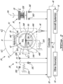
- FIG. 2 is a top plan view of an exemplary controller 24 of flight deck 12 of FIG. 1 .
- Controller 24 may enable an operator of aircraft 10 to control aircraft system 16.
- controller 24 may be considered a momentary, multiple (e.g., three or more) position system controller.
- Controller 24, may include rotatable knob 26 that may be rotatable about rotation axis RA.
- knob 26 may be configured as a rotatable push button that may be used to provide input to aircraft system 16 by way of rotation of knob 26 and also by way of depressing (or pulling) knob 26.
- Knob 26 may be rotatable about rotation axis RA in a first (e.g., counter-clockwise) direction from neutral (e.g., central) angular position N to first angular position P1 associated with a first input to aircraft system 16.
- neutral angular position N of knob 26 may not be associated with any specific input to aircraft system 16, or with any specific state of aircraft system 16.
- first angular position P1 of knob 26 may be used to command an OFF state of aircraft system 16.
- knob 26 may be rotatable about rotation axis RA in a second (e.g., clockwise) direction from neutral angular position N to second angular position P2 associated with a second input to aircraft system 16.
- second angular position P2 of knob 26 may be used to command an ON state of aircraft system 16.
- knob 26 may be connected to double-throw switch 28 as shown in FIG. 2 , or may be connected to multiple single-throw switches for example.
- Switch 28 may include first terminal 30A associated with first angular position P1 of knob 26, second terminal 30B associated with second angular position P2 of knob 26, and common third terminal 30C. Accordingly, electrical communication between first terminal 30A and third terminal 30C may indicate that knob 26 is in first angular position P1, and electrical communication between second terminal 30B and third terminal 30C may indicate that knob 26 is in second angular position P2. Alternatively, the lack of electrical communication between first terminal 30A and third terminal 30C, or between second terminal 30B and third terminal 30C may indicate that knob 26 is in neutral angular position N.
- Knob 26 may be resiliently biased toward neutral angular position N to automatically return to neutral angular position N from first angular position P1 and also from second angular position P2. Such resilient biasing may provide a "return-to-center" behaviour of knob 26 when the operator releases knob 26.
- the resilient biasing of knob 26 toward neutral angular position N may be achieved by way of first spring 32A shown schematically in FIG. 2 .
- the angular displacement of knob 26 may be limited to within a predetermined angular range represented by ⁇ 1+ ⁇ 2 in FIG. 2 . In other words, knob 26 may not be infinitely rotatable about rotation axis RA.
- controller 24 may provide tactile feedback to the operator to indicate that knob 26 has been rotated adequately into position. Such tactile feedback may be provided by a detent such as detent 58 shown in FIG. 4 , or by knob 26 reaching a hard stop for example.
- detents 58 may be incorporated into controller 24 to define additional angular positions that are associated with inputs to aircraft system 16. Such additional angular positions may be intermediate angular positions located between first angular position P1 and angular position P2. Such detents may provide tactile feedback to the operator and also permit controller 24 to be able to supply additional (e.g., more than three types of) inputs to aircraft system 16.
- knob 26 may be configured to provide one or more a tactile cues to the operator to indicate the presence of knob 26, permit the operator to identify knob 26, and also to indicate the angular position of knob 26 relative to neutral angular position N. Such tactile cue(s) may facilitate the use of controller 24 without necessarily having to look at controller 24, and/or in a dark and/or smoke-filled cockpit for example. Controller 24 may be configured for single-hand operation. In some embodiments, a radially outer surface of knob 26 may be non-axisymmetric about rotation axis RA to define one or more tactile cues indicating the angular position of knob 26, and providing tactile confirmation of rotation of knob 26.
- knob 26 may include one or more recesses 34A, 34B that are sized and configured to accommodate part(s) of a hand of the operator.
- two recesses 34A, 34B may be diametrically opposed relative to rotation axis RA.
- recesses 34A, 34B may be laterally opposed to facilitate the grasping of knob 26 between a thumb and an index finger of a same hand for example.
- Recesses 34A, 34B may have substantially identical or different sizes and configurations.
- one or both of recesses 34A, 34B may have an angular span of between 10 degrees and 60 degrees around rotation axis RA.
- Knob 26 may also be linearly movable (e.g., translatable) along rotation axis RA and may be operable as a push button and/or as a pull knob for providing a third input and optionally a fourth input to aircraft system 16.
- Knob 26 may be resiliently biased toward its stowed (pushed) position, toward its deployed (pulled) position or toward an intermediate position between the stowed position and the deployed position by way of a suitable spring.
- knob 26 may additionally be represented as a rotatable and spring-loaded push button 36 as shown schematically in FIG. 2 . Accordingly, the third input may be provided to aircraft system 16 by way of depressing knob 26 to establish electric communication between fourth terminal 30D and fifth terminal 30E for example.
- Knob 26 may be resiliently biased toward its undepressed position by way of second spring 32B. As explained in relation to FIG. 4 , the rotation of knob 26 and pushing of knob 26 may be mutually exclusive in some embodiments.
- knob 26 may instead be configured as a pull knob where the third (or fourth) input may be provided to aircraft system 16 by way of axially pulling on knob 26 to establish electric communication between fourth terminal 30D and fifth terminal 30E for example.
- knob 26 may be configured as a push knob and as a pull knob where the third input is provided to aircraft system 16 by way of axially pushing on knob 26 to establish electric communication between fourth terminal 30D and fifth terminal 30E for example, and where the fourth input is provided to aircraft system 16 by way of axially pulling on knob 26 to establish electric communication between sixth and seventh terminals (not shown) for example.
- knob 26 may be resiliently biased toward an intermediate position in which fourth terminal 30D and fifth terminal 30E are normally electrically disconnected, and the sixth and seventh terminals are also normally electrically disconnected.
- the pushing of knob 26 may provide the third input to aircraft system 16, and the pulling of knob 26 may provide a protection function for controller 24 instead of providing an input to aircraft system 16.
- Such protection function may prevent knob 26 from being rotated to one or both sides of neutral angular position N for example.
- Such protection function may require the operator to perform a second action to override the protection afforded on one or both directions of rotation.
- the pulling of knob 26 may provide the third input to aircraft system 16, and the pushing of knob 26 may provide a protection function for controller 24 instead of providing an input to aircraft system 16.
- Such protection function may prevent knob 26 from being rotated to one or both sides of neutral angular position N for example.
- Such protection function may require the operator to perform a second action to override the protection afforded on one or both directions of rotation.
- the first input, second input and/or third input may be indicative of commanded states of aircraft system 16.
- the first input associated with knob 26 being at first angular position P1 may be indicative of a commanded OFF state of aircraft system 16.
- the second input associated with knob 26 being at second angular position P2 may be indicative of a commanded ON state of aircraft system 16.
- the third input associated with knob 26 being depressed along rotation axis RA may be indicative of a commanded AUTO (i.e., automatic) operating state of aircraft system 16.
- the first input, second input and/or third input may be indicative of set points, operating parameters or other data that may be provided as input to aircraft system 16.
- controller 24 may be operatively connected to computer 38 so that computer 38 may receive the first input, second input and third input from controller 24, and may communicate with aircraft system 16 accordingly.
- computer 38 may include a microcontroller operatively connected to wait for input(s) from controller 24 by monitoring electrical communication between the applicable terminals 30A-30E, and generate suitable output(s) 40 for controlling aircraft system 16.
- computer 38 may be integrated with controller 24.
- Computer 38 may include one or more data processors and one or more computer-readable memories storing machine-readable instructions executable by the data processor(s) and configured to cause the data processor(s) to generate one or more outputs 40 (e.g., signals) for causing the execution of steps of methods described herein.
- computer 38 may be part of an avionics suite of aircraft 10 and may carry out additional functions than those described herein.
- Controller 34 may include annunciator 42, which may display one or more visual (e.g., textual and/or graphical) indications 44A-44C associated with aircraft system 16.
- annunciator 42 may include one or more suitable display devices and/or indicator lights 46 (e.g., light-emitting diodes, incandescent light bulb(s)) associated with one or more of visual indications 44A-44C.
- Visual indications 44A-44C may be disposed and visible within a radially outer periphery of knob 26 when viewed along rotation axis RA as illustrated in FIG. 2 .
- visual indications 44A-44C may be disposed centrally of knob 26.
- Visual indications 44A-44C may be integrated with knob 26, or may be separate from knob 26.
- visual indications 44A-44C may be visible on an upper face of knob 26.
- knob 26 may be rotatable separately of visual indications 44A-44C so that visual indications 44A-44C may remain stationary when knob 26 is rotated.
- visual indications 44A-44C may be visible through a transparent upper face of knob 26, or may be visible through a central opening of knob 26.
- Visual indications 44A-44C may be indicative of the (e.g., ON, OFF, AUTO, FAIL, FAULT) currently active state of aircraft system 16, whether the state of aircraft system 16 was commanded via controller 24 or from another authority such as other source(s) 50.
- visual indications 44A-44C may be indicative of the currently active state of aircraft system 16 irrespective of the first input, the second input and the third input received via knob 26.
- the currently active state of aircraft system 16 may be determined by computer 38 based on a last commanded state of aircraft system 16, whether the last commanded state was commanded via knob 26 or by other source(s) 50.
- the currently active state of aircraft system 16 may be sensed via one or more sensors associated with aircraft system 16 and in data communication with computer 38 so that the currently active state of aircraft system 16 may be determined independently of any input(s) received via knob 26 and/or other source(s) 50.
- Computer 38 may receive external input(s) 48 that are generated externally of controller 24 and that are communicated to computer 38.
- Such external input(s) 48 may include sensed data indicative of a currently active state of aircraft system 16.
- Such external input(s) 48 may include a commanded state of aircraft system 16 received from one or more other sources 50 different from controller 24.
- sources 50 i.e., authorities
- Examples of other sources 50 i.e., authorities
- Examples of other sources 50 i.e., authorities
- Examples of other sources 50 i.e., authorities
- Examples of other sources 50 i.e., authorities
- Another example of another source 50 that may influence the state of aircraft system 16 may be an automated (e.g., auto-flight) system of aircraft 10 that may automatically alter the state of aircraft system 16 based on sensed input for example.
- different states of aircraft system 16 may be annunciated using different colors, and/or by visual indications 44A-44C being displayed in different regions of annunciator 42.
- annunciator 42 may display a first color to indicated a first state of aircraft system 16, a second color to indicate a second state of aircraft system 16, and/or a third color to indicate a third state of aircraft system 16.
- the ON state may represent an operative state of aircraft system 16, and may be annunciated by first visual indication 44A including the letters "ON" shown in green on a black background.
- the OFF state may represent an inoperative state of aircraft system 16, and may be annunciated by second visual indication 44B including the letters "OFF” shown in white on a black background.
- the FAIL state of aircraft system 16 may represent a sensed failure and may be annunciated by third visual indication 44C including the letters "FAIL" shown in black on a yellow background.
- first visual indication 44A may be located in a lower right region of annunciator 42.
- Second visual indication 44B may be located in a lower left region of annunciator 42.
- Third visual indication 44C may be disposed in an upper region of annunciator 42.
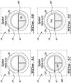
- FIG. 3A-3D are top plan views of controller 24 annunciating different states of aircraft system 16.
- FIG. 3A shows controller 24 in state where annunciator 42 displays no visual indications. The illustration of FIG. 3A may represent a state where aircraft 10 is powered down.
- FIG. 3B shows controller 24 in a state where annunciator 42 displays first visual indication 44A indicating the ON state of aircraft system 16.
- FIG. 3C shows controller 24 in a state where annunciator 42 displays second visual indication 44B indicating the OFF state of aircraft system 16.
- FIG. 3D shows controller 24 in a state where annunciator 42 displays third visual indication 44C indicating the FAIL state of aircraft system 16.
- FIG. 4 is a schematic elevation view of controller 24.
- Knob 26 of controller may be mounted onto stem 52. Part of stem 52 may be received inside of knob 26 so that knob 26 may be rotatable and translatable relative to stem 52.
- Stem 52 may be attached to overhead panel 22.
- annunciator 42 may be located at an end of stem 52 opposite of overhead panel 22.
- the rotation of knob 26 about rotation axis RA may be limited to prevent infinite rotation of knob 26 about rotation axis RA.
- hard stops may be used to limit the rotation of knob 26 within the desired angular displacement range.
- the hard stops may be defined by way of slot 54 defined in stem 52, and cooperating pin 56 attached to knob 26. Pin 56 may extend into slot 54, and be movably engaged with slot 54.
- the shape of slot 54 may be selected to limit the rotational and translational movement of knob 26 relative to stem 52.
- FIG. 4 shows pin 56 at neutral angular position N.
- FIG. 4 also shows in broken lines other potential positions of pin 56 corresponding to first angular position P1 (i.e., first input to aircraft system 16) and second angular position P2 (i.e., second input to aircraft system 16).
- slot 54 may be T-shaped to also permit pressing of knob 26 as a push button.
- FIG. 4 also shows potential position D of pin 56 corresponding to the depressed position of knob 26 to provide the third input to aircraft system 16.
- Second spring 32B may be a compressive spring biasing knob 26 away from overhead panel 22.
- knob 26 and the pushing (or pulling) of knob 26 may be mutually exclusive in some embodiments.
- the configuration shown in FIG. 4 may prevent knob 26 from being rotated and simultaneously moved axially for the purpose of providing system input.
- slot 54 and pin 56 may prevent knob 26 from being moved axially.
- rotation of knob 26 may then be prevented.
- Slot 54 may include one or more optional detents 58 in the form of protrusions that may hinder the movement of pin 56 inside slot 54 in order to define one or more additional angular positions that are associated with additional inputs that may be provided to aircraft system 16 via knob 26.
- Detent(s) 58 may include any suitable mechanism than may keep pin 56 in a certain position relative to slot 54, and which can be released by the application of force to pin 56 for example.
- FIG. 4 shows two detents 58 defining a third angular position P3 of pin 56 therebetween. Third angular position P3 may be located between neutral angular position N and first angular position P1, or between neutral angular position N and second angular position P2.
- a slot having an inverted T-shape could instead be used to permit pulling of knob 26 instead of depressing knob 26, and a suitable second spring may be configured to bias knob 26 toward overhead panel 22 instead. It is understood that a suitable slot could instead be formed in a surface of knob 26, and that a cooperating pin could instead be attached to stem 52.
- FIG. 5 is a schematic elevation view of another exemplary controller 124.
- Controller 124 may include elements of controller 24 described above, and like elements are identified using like reference numerals.
- controller 124 may have T-shaped slot 154 which may define a releasable lock preventing rotation of knob 26 from neutral angular position N of knob 26.
- the releasable lock may be useful in preventing unintentional rotation of knob 26.
- neutral angular position N may also correspond to locked position L of knob 26. In the locked position L, rotation of knob 26 may be prevented.
- Wining of knob 26 along rotation axis RA and away from overhead panel 22 so that pin 56 adopts released position R may unlock the rotation of knob 26 and permit knob 26 to be rotated so that pin 56 may adopt first angular position P1 (i.e., first input to aircraft system 16) and second angular position P2 (i.e., second input to aircraft system 16).
- Slot 154 could instead have a shape that provides a releasable lock that prevents rotation of knob 26 in only one direction or in both directions.
- a depression of knob 26 so that pin 56 adopts depressed position D may be used to provide the third input to aircraft system 16.
- controller 124 could also be configured so that unlocking of knob 26 and the generation of the third input may be done by pushing knob 26 toward overhead panel 22.
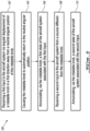
- FIG. 6 is a flow diagram of method 100 of interfacing with an aircraft system 16.
- Method 100 may be executed using controller 24, 124 described herein or using another controller. Aspects of controllers 24, 124 may be incorporated into method 100.
- method 100 may include:
- Annunciating the different states of aircraft system 16 may be done by providing one or more (e.g., graphical, textual) visual indications 44A-44C.
- method 100 may include: receiving a third input to aircraft system 16 via angular displacement of knob 26 in a second direction away from neutral angular position N of knob 26.
- the second direction may be opposite the first direction.
- Knob 26 may be caused to automatically return to neutral angular position N by resilient biasing provided by first spring 32A for example.
- Method 100 may include annunciating, via knob 26, a third state of aircraft system 16 associated with the third input.
- Method 100 may include receiving a fourth input to aircraft system via linear displacement of knob 26.
- Method 100 may include preventing knob 26 from being rotated by more than 180 degrees.
Landscapes
- Engineering & Computer Science (AREA)
- Aviation & Aerospace Engineering (AREA)
- Chemical & Material Sciences (AREA)
- Combustion & Propulsion (AREA)
- Transportation (AREA)
- Mechanical Engineering (AREA)
- Automation & Control Theory (AREA)
- Mechanical Control Devices (AREA)
Applications Claiming Priority (1)
| Application Number | Priority Date | Filing Date | Title |
|---|---|---|---|
| US202263350480P | 2022-06-09 | 2022-06-09 |
Publications (1)
| Publication Number | Publication Date |
|---|---|
| EP4289725A1 true EP4289725A1 (fr) | 2023-12-13 |
Family
ID=84568899
Family Applications (1)
| Application Number | Title | Priority Date | Filing Date |
|---|---|---|---|
| EP22215541.8A Pending EP4289725A1 (fr) | 2022-06-09 | 2022-12-21 | Controleur de systeme d'aeronef et methode associee |
Country Status (4)
| Country | Link |
|---|---|
| US (1) | US20230399121A1 (fr) |
| EP (1) | EP4289725A1 (fr) |
| CN (1) | CN117215221A (fr) |
| CA (1) | CA3185437A1 (fr) |
Citations (6)
| Publication number | Priority date | Publication date | Assignee | Title |
|---|---|---|---|---|
| US20150134183A1 (en) * | 2011-04-19 | 2015-05-14 | Ford Global Technologies, Llc | Intuitive driver interface for trailer backup assist |
| US20180029502A1 (en) * | 2015-02-23 | 2018-02-01 | Jaguar Land Rover Limited | Seat control apparatus |
| US10606301B2 (en) * | 2017-06-27 | 2020-03-31 | Ge Aviation Systems Limited | Tactile gain control |
| US10786273B2 (en) * | 2018-07-13 | 2020-09-29 | Covidien Lp | Rotation knob assemblies for handle assemblies |
| US20210070427A1 (en) * | 2019-09-06 | 2021-03-11 | Lockheed Martin Corporation | Advanced mission interaction control yoke for advanced autopilots or autonomous aircraft |
| US20210333806A1 (en) * | 2020-04-27 | 2021-10-28 | Honeywell International Inc. | Flight guidance controller interface |
Family Cites Families (6)
| Publication number | Priority date | Publication date | Assignee | Title |
|---|---|---|---|---|
| JP6189731B2 (ja) * | 2013-12-03 | 2017-08-30 | 株式会社東海理化電機製作所 | シフト装置 |
| US9126677B1 (en) * | 2014-10-16 | 2015-09-08 | Sydney Robert Curtis | Universal multi-role aircraft protocol |
| US10108189B2 (en) * | 2016-07-29 | 2018-10-23 | Ge Aviation Systems Llc | Integrated flight management system and flight director |
| US10353510B2 (en) * | 2016-08-26 | 2019-07-16 | Motorola Solutions, Inc. | Force-scalable stationary interface control |
| US10144504B1 (en) * | 2017-09-01 | 2018-12-04 | Kitty Hawk Corporation | Decoupled hand controls for aircraft with vertical takeoff and landing and forward flight capabilities |
| US20250033472A1 (en) * | 2023-07-26 | 2025-01-30 | Clarion Corporation of America | Rotatable electronic device |
-
2022
- 2022-12-21 CA CA3185437A patent/CA3185437A1/fr active Pending
- 2022-12-21 EP EP22215541.8A patent/EP4289725A1/fr active Pending
- 2022-12-22 US US18/087,079 patent/US20230399121A1/en active Pending
- 2022-12-29 CN CN202211704327.8A patent/CN117215221A/zh active Pending
Patent Citations (6)
| Publication number | Priority date | Publication date | Assignee | Title |
|---|---|---|---|---|
| US20150134183A1 (en) * | 2011-04-19 | 2015-05-14 | Ford Global Technologies, Llc | Intuitive driver interface for trailer backup assist |
| US20180029502A1 (en) * | 2015-02-23 | 2018-02-01 | Jaguar Land Rover Limited | Seat control apparatus |
| US10606301B2 (en) * | 2017-06-27 | 2020-03-31 | Ge Aviation Systems Limited | Tactile gain control |
| US10786273B2 (en) * | 2018-07-13 | 2020-09-29 | Covidien Lp | Rotation knob assemblies for handle assemblies |
| US20210070427A1 (en) * | 2019-09-06 | 2021-03-11 | Lockheed Martin Corporation | Advanced mission interaction control yoke for advanced autopilots or autonomous aircraft |
| US20210333806A1 (en) * | 2020-04-27 | 2021-10-28 | Honeywell International Inc. | Flight guidance controller interface |
Also Published As
| Publication number | Publication date |
|---|---|
| US20230399121A1 (en) | 2023-12-14 |
| CN117215221A (zh) | 2023-12-12 |
| CA3185437A1 (fr) | 2023-12-09 |
Similar Documents
| Publication | Publication Date | Title |
|---|---|---|
| US9424753B2 (en) | Simplified user interface for an aircraft | |
| US9710145B2 (en) | Human machine interface device for aircraft | |
| US9471176B2 (en) | Flight deck touch-sensitive hardware controls | |
| EP2827104B1 (fr) | Systèmes d'affichage et procédés permettant des affichages ayant une fonctionnalité de pilote automatique intégrée | |
| US6980198B1 (en) | Multifunction keyboard for advanced cursor driven avionic flight decks | |
| EP2674829B1 (fr) | Manette latérale | |
| US20040158364A1 (en) | Aircraft dialog device for dialog with system of aircraft | |
| EP2022040B1 (fr) | Poignée de centre de commande multifonctionnelle pour un véhicule | |
| WO2025165399A2 (fr) | Interface utilisateur pour vol automatisé | |
| US8083186B2 (en) | Input/steering mechanisms and aircraft control systems for use on aircraft | |
| EP4289725A1 (fr) | Controleur de systeme d'aeronef et methode associee | |
| US20190352018A1 (en) | Aircraft flight guidance panels with a display disposed between two input portions | |
| US10589844B2 (en) | Method of controlling aerodynamic means of an aircraft, an associated control system, and an aircraft provided with such a control system | |
| EP3018571B1 (fr) | Unité de sélection pour sélectionner ou commander de différents états ou des fonctions d'un système d'avion | |
| US20230067957A1 (en) | Aircraft lockout / tagout for pushbutton switch | |
| RU2828758C1 (ru) | Способ управления бортовым оборудованием многофункционального одноместного боевого летательного аппарата | |
| Fan et al. | Design of Touch Control Display Interface Based on Synoptic Page in Civil Aircraft Cockpit | |
| RU2773989C1 (ru) | Система оперативного управления оборудованием подвижного объекта | |
| WO2010079477A2 (fr) | Poste de travail pour commande de plateforme située à distance | |
| GB2267953A (en) | Control system with plural manual control members. | |
| CN118723100A (zh) | 用于飞行器的多功能控制面板 | |
| CN113212773A (zh) | 一种用于控制飞行器的飞行模式的集成式控制系统及控制方法 | |
| Bateman | Investigation of Arrangement of Multipurpose Displays and Use of Tailored Control Logic in a Fighter Aircraft Cockpit | |
| SI23371A (sl) | Nov uporabniški vmesnik za nadzor nad sistemom za uravnovešanje leta letala | |
| JPH09315395A (ja) | 計器板表示器の制御方法 |
Legal Events
| Date | Code | Title | Description |
|---|---|---|---|
| PUAI | Public reference made under article 153(3) epc to a published international application that has entered the european phase |
Free format text: ORIGINAL CODE: 0009012 |
|
| STAA | Information on the status of an ep patent application or granted ep patent |
Free format text: STATUS: REQUEST FOR EXAMINATION WAS MADE |
|
| 17P | Request for examination filed |
Effective date: 20221221 |
|
| AK | Designated contracting states |
Kind code of ref document: A1 Designated state(s): AL AT BE BG CH CY CZ DE DK EE ES FI FR GB GR HR HU IE IS IT LI LT LU LV MC ME MK MT NL NO PL PT RO RS SE SI SK SM TR |
|
| STAA | Information on the status of an ep patent application or granted ep patent |
Free format text: STATUS: EXAMINATION IS IN PROGRESS |
|
| 17Q | First examination report despatched |
Effective date: 20260223 |