EP4290077A1 - An einem spiralverdichter angewandte feste spirale und spiralverdichter - Google Patents
An einem spiralverdichter angewandte feste spirale und spiralverdichter Download PDFInfo
- Publication number
- EP4290077A1 EP4290077A1 EP23762130.5A EP23762130A EP4290077A1 EP 4290077 A1 EP4290077 A1 EP 4290077A1 EP 23762130 A EP23762130 A EP 23762130A EP 4290077 A1 EP4290077 A1 EP 4290077A1
- Authority
- EP
- European Patent Office
- Prior art keywords
- scroll
- oil supply
- supply groove
- working medium
- stationary
- Prior art date
- Legal status (The legal status is an assumption and is not a legal conclusion. Google has not performed a legal analysis and makes no representation as to the accuracy of the status listed.)
- Granted
Links
Images


Classifications
-
- F—MECHANICAL ENGINEERING; LIGHTING; HEATING; WEAPONS; BLASTING
- F04—POSITIVE - DISPLACEMENT MACHINES FOR LIQUIDS; PUMPS FOR LIQUIDS OR ELASTIC FLUIDS
- F04C—ROTARY-PISTON, OR OSCILLATING-PISTON, POSITIVE-DISPLACEMENT MACHINES FOR LIQUIDS; ROTARY-PISTON, OR OSCILLATING-PISTON, POSITIVE-DISPLACEMENT PUMPS
- F04C18/00—Rotary-piston pumps specially adapted for elastic fluids
- F04C18/02—Rotary-piston pumps specially adapted for elastic fluids of arcuate-engagement type, i.e. with circular translatory movement of co-operating members, each member having the same number of teeth or tooth-equivalents
- F04C18/0207—Rotary-piston pumps specially adapted for elastic fluids of arcuate-engagement type, i.e. with circular translatory movement of co-operating members, each member having the same number of teeth or tooth-equivalents both members having co-operating elements in spiral form
- F04C18/0215—Rotary-piston pumps specially adapted for elastic fluids of arcuate-engagement type, i.e. with circular translatory movement of co-operating members, each member having the same number of teeth or tooth-equivalents both members having co-operating elements in spiral form where only one member is moving
-
- F—MECHANICAL ENGINEERING; LIGHTING; HEATING; WEAPONS; BLASTING
- F04—POSITIVE - DISPLACEMENT MACHINES FOR LIQUIDS; PUMPS FOR LIQUIDS OR ELASTIC FLUIDS
- F04C—ROTARY-PISTON, OR OSCILLATING-PISTON, POSITIVE-DISPLACEMENT MACHINES FOR LIQUIDS; ROTARY-PISTON, OR OSCILLATING-PISTON, POSITIVE-DISPLACEMENT PUMPS
- F04C18/00—Rotary-piston pumps specially adapted for elastic fluids
- F04C18/02—Rotary-piston pumps specially adapted for elastic fluids of arcuate-engagement type, i.e. with circular translatory movement of co-operating members, each member having the same number of teeth or tooth-equivalents
- F04C18/0207—Rotary-piston pumps specially adapted for elastic fluids of arcuate-engagement type, i.e. with circular translatory movement of co-operating members, each member having the same number of teeth or tooth-equivalents both members having co-operating elements in spiral form
- F04C18/0246—Details concerning the involute wraps or their base, e.g. geometry
- F04C18/0253—Details concerning the base
-
- F—MECHANICAL ENGINEERING; LIGHTING; HEATING; WEAPONS; BLASTING
- F04—POSITIVE - DISPLACEMENT MACHINES FOR LIQUIDS; PUMPS FOR LIQUIDS OR ELASTIC FLUIDS
- F04C—ROTARY-PISTON, OR OSCILLATING-PISTON, POSITIVE-DISPLACEMENT MACHINES FOR LIQUIDS; ROTARY-PISTON, OR OSCILLATING-PISTON, POSITIVE-DISPLACEMENT PUMPS
- F04C29/00—Component parts, details or accessories of pumps or pumping installations, not provided for in groups F04C18/00 - F04C28/00
-
- F—MECHANICAL ENGINEERING; LIGHTING; HEATING; WEAPONS; BLASTING
- F04—POSITIVE - DISPLACEMENT MACHINES FOR LIQUIDS; PUMPS FOR LIQUIDS OR ELASTIC FLUIDS
- F04C—ROTARY-PISTON, OR OSCILLATING-PISTON, POSITIVE-DISPLACEMENT MACHINES FOR LIQUIDS; ROTARY-PISTON, OR OSCILLATING-PISTON, POSITIVE-DISPLACEMENT PUMPS
- F04C29/00—Component parts, details or accessories of pumps or pumping installations, not provided for in groups F04C18/00 - F04C28/00
- F04C29/02—Lubrication; Lubricant separation
-
- F—MECHANICAL ENGINEERING; LIGHTING; HEATING; WEAPONS; BLASTING
- F04—POSITIVE - DISPLACEMENT MACHINES FOR LIQUIDS; PUMPS FOR LIQUIDS OR ELASTIC FLUIDS
- F04C—ROTARY-PISTON, OR OSCILLATING-PISTON, POSITIVE-DISPLACEMENT MACHINES FOR LIQUIDS; ROTARY-PISTON, OR OSCILLATING-PISTON, POSITIVE-DISPLACEMENT PUMPS
- F04C29/00—Component parts, details or accessories of pumps or pumping installations, not provided for in groups F04C18/00 - F04C28/00
- F04C29/02—Lubrication; Lubricant separation
- F04C29/023—Lubricant distribution through a hollow driving shaft
-
- F—MECHANICAL ENGINEERING; LIGHTING; HEATING; WEAPONS; BLASTING
- F04—POSITIVE - DISPLACEMENT MACHINES FOR LIQUIDS; PUMPS FOR LIQUIDS OR ELASTIC FLUIDS
- F04C—ROTARY-PISTON, OR OSCILLATING-PISTON, POSITIVE-DISPLACEMENT MACHINES FOR LIQUIDS; ROTARY-PISTON, OR OSCILLATING-PISTON, POSITIVE-DISPLACEMENT PUMPS
- F04C29/00—Component parts, details or accessories of pumps or pumping installations, not provided for in groups F04C18/00 - F04C28/00
- F04C29/02—Lubrication; Lubricant separation
- F04C29/028—Means for improving or restricting lubricant flow
-
- F—MECHANICAL ENGINEERING; LIGHTING; HEATING; WEAPONS; BLASTING
- F04—POSITIVE - DISPLACEMENT MACHINES FOR LIQUIDS; PUMPS FOR LIQUIDS OR ELASTIC FLUIDS
- F04C—ROTARY-PISTON, OR OSCILLATING-PISTON, POSITIVE-DISPLACEMENT MACHINES FOR LIQUIDS; ROTARY-PISTON, OR OSCILLATING-PISTON, POSITIVE-DISPLACEMENT PUMPS
- F04C23/00—Combinations of two or more pumps, each being of rotary-piston or oscillating-piston type, specially adapted for elastic fluids; Pumping installations specially adapted for elastic fluids; Multi-stage pumps specially adapted for elastic fluids
- F04C23/008—Hermetic pumps
Definitions
- the present disclosure relates to the field of compressors, and more particularly, to a stationary scroll applied in a scroll compressor and a scroll compressor having the stationary scroll applied in the scroll compressor.
- the existing scroll compressor comprises a stationary scroll, an orbiting scroll, and a crankshaft.
- the orbiting scroll is mounted on the crankshaft, and the orbiting scroll is assembled with the stationary scroll and is movable relative to the stationary scroll.
- the crankshaft performs an eccentric motion
- the orbiting scroll performs a revolution motion, to achieve suction, compression, and exhaust of the compressor.
- the stationary scroll and the orbiting scroll are assembled together, the stationary scroll and the orbiting scroll are brought into contact with each other.
- the orbiting scroll rotates, only the orbiting scroll operates to passively lubricate a contact surface between the stationary scroll and the orbiting scroll with oil.
- the lubricating oil between the stationary scroll and the orbiting scroll is less, and an oil film cannot be formed between the stationary scroll and the orbiting scroll, which easily leads to serious wear of the contact surface between the stationary scroll and the orbiting scroll.
- service life of the stationary scroll and the orbiting scroll would be affected.
- no reliable seal can be formed between the stationary scroll and the orbiting scroll, and a large pressure difference will be generated between a pressure in the back pressure chamber of the compressor and a suction pressure. In this way, the back pressure may leak to a working medium flow groove through a gap between the orbiting scroll and the stationary scroll, which leads a working medium to be repeatedly compressed, resulting in an increase in a power of the scroll compressor and a decrease in energy efficiency of the scroll compressor.
- the present disclosure is intended to solve at least to some extent one of the technical problems in the related art.
- an object of the present disclosure is to propose a stationary scroll for a scroll compressor.
- a closed annular oil supply groove By forming a closed annular oil supply groove, contact surfaces between an orbiting scroll and a stationary scroll can be sufficiently lubricated.
- wear between the orbiting scroll and the stationary scroll can be reduced to achieve a complete sealing between a working medium flow groove and a back pressure chamber. Therefore, an increase in a power of the scroll compressor can be avoided, and thus energy efficiency and performance of the scroll compressor can be improved.
- Another object of the present disclosure is to provide a scroll compressor.
- a stationary scroll for a scroll compressor comprises: a scroll body defining a working medium flow groove with an open end; a scroll wrap disposed within the working medium flow groove to form a scroll chamber; and a closed annular oil supply groove formed on the scroll body and surrounding an open end of the working medium flow groove.
- the oil supply groove is adapted to be in communication with an oil outlet hole of an orbiting scroll of the scroll compressor.
- the closed annular oil supply groove By forming the closed annular oil supply groove, contact surfaces between the orbiting scroll and the stationary scroll can be sufficiently lubricated by the lubricating oil to reduce the wear between the orbiting scroll and the stationary scroll.
- the closed annular oil supply groove can provide the complete sealing between the working medium flow groove and the back pressure chamber to avoid leakage of the back pressure into the working medium flow groove through a gap at the contact end surfaces of the orbiting scroll and the stationary scroll, which in turn prevents the working medium being repeatedly compressed. As a result, an increase in the power of the scroll compressor can be avoided. Therefore, the energy efficiency and the performance of the scroll compressor can be improved.
- an inner side wall of the oil supply groove is spaced apart from the working medium flow groove in a radial direction of the stationary scroll.
- a spacing between the inner side wall of the oil supply groove and the working medium flow groove is A, wherein 1 mm ⁇ A.
- an open end of the oil supply groove is adapted to be covered with the orbiting scroll.
- a width of the oil supply groove is B, wherein 1.2 mm ⁇ B ⁇ 2 mm.
- a depth of the oil supply groove is C, wherein 0.5 mm ⁇ C ⁇ 1.8 mm.
- an inner side wall of the oil supply groove has a recess recessed towards an inner side of the scroll body and adapted to be in communication with the oil outlet hole.
- the recess is formed as an arc-shaped recess.
- the oil supply groove has a recessed segment recessed towards a radial inner side of the scroll body, the recessed segment abutting on the recess.
- the recessed segment is formed as an arc-shaped segment.
- a scroll compressor according to an embodiment of the present disclosure comprises the stationary scroll for the scroll compressor as described above.
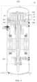
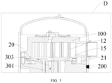
- a stationary scroll 100 according to an embodiment of the present disclosure will be described below with reference to FIGS. 1 to 5 .
- the stationary scroll 100 may be for a scroll compressor 300, and the present disclosure is not limited thereto.
- the stationary scroll 100 may be also for other devices requiring the stationary scroll 100.
- the present disclosure will be described with reference to the stationary scroll 100 for a scroll compressor 300.
- a stationary scroll 100 comprises a scroll body 10, a scroll wrap 12, and a closed annular oil supply groove 13.
- the scroll body 10 defines a working medium flow groove 11 with an open end.
- the scroll wrap 12 is disposed within the working medium flow groove 11 to form a scroll chamber.
- the working medium flow groove 11 may be divided into a working medium inlet chamber 111 and a working medium compression chamber 112 by the scroll wrap 12.
- the working medium inlet chamber 111 and the working medium compression chamber 112 constitute the scroll chamber.
- the scroll body 10 has a working medium inlet and a working medium outlet 14.
- the scroll chamber is in communication with both the working medium inlet and the working medium outlet 14.
- the working medium inlet chamber 111 communicates the working medium inlet and the working medium compression chamber 112.
- the working medium outlet 14 is in communication with the working medium compression chamber 112.
- the scroll wrap 12 is constructed as a scroll-shaped plate-like structure, and the scroll wrap 12 can divide the working medium flow groove 11 into an arc-shaped working medium inlet chamber 111 and a scroll-shaped working medium compression chamber 112 by arranging the scroll wrap 12 in the working medium flow groove 11.
- the working medium inlet chamber 111 and the working medium compression chamber 112 are working medium flow channels.
- a working medium flows into the working medium inlet chamber 111 through the working medium inlet.
- the working medium in the working medium inlet chamber 111 flows into the working medium compression chamber 112 along the working medium inlet chamber 111, and finally flows out of the working medium outlet 14.
- the closed annular oil supply groove 13 is formed around the open end of the working medium flow groove 11 on the scroll body 10.
- the oil supply groove 13 is adapted to be in communication with an oil outlet hole 20 of the orbiting scroll 200 of the scroll compressor 300. Through a cooperation between the oil supply groove 13 and the oil outlet hole 20, a lubricating oil flows into the oil supply groove 13 from the oil outlet hole 20 to sufficiently lubricate a contact surface between the orbiting scroll 200 and the stationary scroll 100.
- a crankshaft 301 of the scroll compressor 300 rotates, and the lubricating oil in an oil sump 302 of the scroll compressor 300 is delivered to the oil outlet hole 20 of the orbiting scroll 200 through an oil supply channel 303 of the crankshaft 301 under a coupling action of a pressure difference.
- the orbiting scroll 200 moves relative to the stationary scroll 100 to communicate the oil outlet hole 20 and the oil supply groove 13, the lubricating oil flows into the oil supply groove 13 from the oil outlet hole 20.
- the lubricating oil is delivered between the orbiting scroll 200 and the stationary scroll 100 to provide sufficient lubrication for contact end surfaces of the orbiting scroll 200 and the stationary scroll 100, thereby reducing a friction force between the contact end surfaces of the orbiting scroll 200 and the stationary scroll 100. Therefore, a normal operation between the orbiting scroll 200 and the stationary scroll 100 can be ensured, and the wear between the orbiting scroll 200 and the stationary scroll 100 can be reduced, thereby prolonging the service life of the orbiting scroll 200 and the stationary scroll 100.
- the oil supply groove 13 into the closed annular structure, after the lubricating oil flows into the oil supply groove 13 from the oil outlet hole 20, the lubricating oil is simultaneously supplied in both directions along the oil supply groove 13, ensuring that sufficient lubricating oil is present in a region wherein the orbiting scroll 200 and the stationary scroll 100 are in contact with each other, which in turn avoids dry friction between the contact end surfaces of the orbiting scroll 200 and the stationary scroll 100 due to insufficient oil supply.
- the oil supply groove 13 as the closed annular structure, after the lubricating oil flows into the oil supply groove 13 from the oil outlet hole 20, when the oil supply groove 13 is filled with the lubricating oil, there is a predetermined pressure in the oil supply groove 13, an oil film is easily formed between the contact surfaces of the orbiting scroll 200 and the stationary scroll 100.
- the oil film can separate the working medium flow groove 11 from the back pressure chamber 21, to realize a complete sealing between the working medium flow groove 11 and a back pressure chamber 21. Therefore, it is possible to avoid the leakage of the back pressure into the working medium flow groove 11 through a gap between the contact end surfaces of the orbiting scroll 200 and the stationary scroll 100, to prevent the power of the scroll compressor 300 from increasing due to repeated compression of the working medium.
- the energy efficiency of the scroll compressor 300 can be enhanced to improve the performance of the scroll compressor 300.
- the closed annular oil supply groove 13 the lubrication of the whole region between the orbiting scroll 200 and the stationary scroll 100 can be achieved, thereby avoiding the dry friction at the contact end surfaces of the orbiting scroll 200 and the stationary scroll 100. As a result, a friction force between the orbiting scroll 200 and the stationary scroll 100 can be reduced, thereby improving the operating performance of the scroll compressor 300. Further, after the lubricating oil flows into the oil supply groove 13 through the oil outlet hole 20, the closed annular oil supply groove 13 can provide bidirectional supply of the lubricating oil, ensuring that the lubricating oil is present in the whole region between the orbiting scroll 200 and the stationary scroll 100 in a circumferential direction.
- the lubricating oil in the oil supply groove 13 can separate the working medium compression chamber 112 from the back pressure chamber 21, to achieve a complete sealing between the working medium compression chamber 112 and the back pressure chamber 21.
- an inner sidewall 133 of the oil supply groove 13 is spaced apart from the working medium flow groove 11.
- the oil supply groove 13 extends in the circumferential direction of the stationary scroll 100.
- the oil supply groove 13 is a closed annular groove formed around the open end of the working medium flow groove 11. In a radial direction of the stationary scroll 100, by spacing the inner side wall 133 of the oil supply groove 13 apart from the working medium flow groove 11, a predetermined distance is generated between the inner side wall 133 of the oil supply groove 13 and the working medium flow groove 11.
- the complete sealing between the working medium flow groove 11 and the back pressure chamber 21 can be ensured, which in turn avoids the leakage of the back pressure into the working medium flow groove 11 through the gap between the contact end surfaces of the orbiting scroll 200 and the stationary scroll 100, to further prevent the power of the scroll compressor 300 from increasing due to the repeated compression of the working medium. Therefore, the energy efficiency and the performance of the scroll compressor 300 can be further improved.
- a spacing between the inner side wall 133 of the oil supply groove 13 and the working medium flow groove 11 is A, wherein 1 mm ⁇ A. It should be noted that in the radial direction of the stationary scroll 100, the inner side wall 133 of the oil supply groove 13 is spaced apart from the working medium flow groove 11, and the spacing between the inner side wall 133 of the oil supply groove 13 and the working medium flow groove 11 is greater than or equal to 1 mm.
- the spacing between the inner side wall 133 of the oil supply groove 13 and the working medium flow groove 11 may be variable or constant.
- the spacing between the inner side wall 133 of the oil supply groove 13 and the working medium flow groove 11 at each region may be set as desired as long as a minimum spacing between the inner side wall 133 of the oil supply groove 13 and the working medium flow groove 11 is 1 mm.
- the dry friction between the contact surfaces of the orbiting scroll 200 and the stationary scroll 100 due to the leakage of the lubricating oil can be avoided, which may result in wear of the contact surfaces of the orbiting scroll 200 and the stationary scroll 100. Therefore, the service life of the stationary scroll 100 and the orbiting scroll 200 can be prolonged.
- the open end of oil supply groove 13 is adapted to be covered with the orbiting scroll 200.
- the orbiting scroll 200 is located below the stationary scroll 100, and the scroll wrap of the orbiting scroll 200 extends into the working medium flow groove 11.
- the oil supply groove 13 is formed on a lower surface of the scroll body 10, and a lower end of the oil supply groove 13 is opened.
- the outer side wall 134 of the oil supply groove 13 is located inside the orbiting scroll 200, and the orbiting scroll 200 covers the open end of the oil supply groove 13.
- the orbiting scroll 200 can cover the open end of the oil supply groove 13 in real time, to avoid communication between the oil supply groove 13 and the back pressure chamber 21. After the lubricating oil flows into the oil supply groove 13 from the oil outlet hole 20, the leakage of the lubricating oil in the oil supply groove 13 can be avoided. Therefore, it is possible to ensure that the contact surfaces between the stationary scroll 100 and the orbiting scroll 200 can be sufficiently lubricated with the lubricating oil in the oil supply groove 13.
- a spacing between the outer side wall 134 of the oil supply groove 13 and the outer edge of the orbiting scroll 200 is greater than or equal to 1 mm. In this way, it can be ensured that the outer side wall 134 of the oil supply groove 13 is located inside the orbiting scroll 200 in the radial direction of the stationary scroll 100, and the lubricating oil in the oil supply groove 13 can separate the oil supply groove 13 from the back pressure chamber 21, effectively avoiding the leakage of the lubricating oil in the oil supply groove 13.
- the greater the spacing between the outer side wall 134 of the oil supply groove 13 and the back pressure chamber 21 is, the better the sealing performance between the oil supply groove 13 and the back pressure chamber 21 is.
- the lubricating oil in the oil supply groove 13 can space the working medium flow groove 11 apart from the back pressure chamber 21, to achieve the complete sealing between the working medium flow groove 11 and the back pressure chamber 21.
- the power of the scroll compressor 300 can be reduced, and the working performance of the scroll compressor 300 can be improved.
- a width of the oil supply groove 13 is B, wherein 1.2 mm ⁇ B ⁇ 2 mm.
- the width of the oil supply groove 13 is B.
- B is a value of 1.2 mm, 1.5 mm, 2 mm, or the like.
- the width of the oil supply groove 13 to be B, the lubricating oil of an appropriate amount will be present in the oil supply groove 13.
- the width of the oil supply groove 13 may be set based on actual usage requirements of the scroll compressor 300.
- a depth of the oil supply groove 13 is C, wherein 0.5 mm ⁇ C ⁇ 1.8 mm.
- C is a value of 0.5 mm, 1.5 mm, 1.8 mm, and the like.
- the oil supply groove 13 is recessed towards an inner side of the scroll body 10.
- An end of the oil supply groove 13 close to the orbiting scroll 200 is opened to form the oil supply groove 13 with a depth C. It should be noted that the greater the depth of the oil supply groove 13 is, the greater the amount of lubricating oil contained in the oil supply groove 13 is.
- the sufficient lubricating oil can be supplied between the contact end surfaces of the orbiting scroll 200 and the stationary scroll 100.
- sufficient lubricating oil cannot be supplied between the contact end surfaces of the orbiting scroll 200 and the stationary scroll 100, which may result in the dry friction between the contact surfaces of the orbiting scroll 200 and the stationary scroll 100, thereby resulting in local abnormal wear.
- the depth of the oil supply groove 13 to be C, the lubricating oil of an appropriate amount in the oil supply groove 13 can be ensured.
- the depth of the oil supply groove 13 may be set based on the actual usage requirements of the scroll compressor 300.
- the inner side wall 133 of the oil supply groove 13 has a recess 131 recessed towards the inner side of the scroll body 10.
- the recess 131 is adapted to be in communication with the oil outlet hole 20.
- the oil outlet hole 20 can be in communication with the recess 131, and the lubricating oil can thus flow into the recess 131 through the oil outlet hole 20.
- an oil supply from the recess 131 to the oil supply groove 13 can be realized.
- a duration during which the oil outlet hole 20 is in communication with the oil supply groove 13 can be increased, and thus the duration can be prolonged, which in turn ensures sufficient oil supply to the oil supply groove 13.
- the lubricating effect between the orbiting scroll 200 and the stationary scroll 100 can be enhanced, and the sealing effect between the orbiting scroll 200 and the stationary scroll 100 can be also enhanced.
- the recess 131 is formed as an arc-shaped recess. Further, the recess 131 is constructed as a semi-circular arc-shaped recess recessed towards the inner side of the scroll body 10. After the lubricating oil flows into the semi-circular arc-shaped recess through the oil outlet hole 20, the lubricating oil is uniformly divided into the oil supply grooves 13 on two sides through an arc-shaped surface of the arc-shaped recess, to achieve uniform oil supply to the oil supply groove 13 in two directions, ensuring oil supply in the whole region between the orbiting scroll 200 and the stationary scroll 100.
- the complete sealing between the working medium flow groove 11 and the back pressure chamber 21 can be realized, to avoid the leakage of the back pressure into the working medium flow groove 11 through the gap between the end surfaces of the orbiting scroll 200 and the stationary scroll 100. Therefore, the performance of the scroll compressor 300 can be enhanced.
- the recess 131 as the arc-shaped recess, it is possible to further increase the duration during which the oil outlet hole 20 is in communication with the oil supply groove 13, thereby further ensuring sufficient oil supply to the oil supply groove 13. Therefore, the lubricating effect between the orbiting scroll 200 and the stationary scroll 100 can be further improved.
- the oil supply groove 13 has a recessed segment 132 recessed towards the radial inner side of the scroll body 10, and the recessed segment 132 abuts on the recess 131. Further, in the circumferential direction of the scroll body 10, at least one side of the recess 131 is provided with the recessed segment 132. That is, the recessed segment 132 may be provided only on one side of the recess 131, and the recessed segment 132 may also be provided on two sides of the recess 131.
- the recessed segment 132 is formed as an arc-shaped segment.
- the recess 131 can be in communication with the oil supply groove 13 through the arc-shaped segment, effectively ensuring that the interface formed at the connection between the recess 131 and the oil supply groove 13 has no sharp portion, which facilitates the flow of the lubricating oil from the recess 131 into the oil supply groove 13. Therefore, the lubricating oil can smoothly flow in the oil supply groove 13. Further, it is possible to avoid the wear caused due to the sharp portion formed at the connection between the recess 131 and the oil supply groove 13.
- a scroll compressor 300 according to an embodiment of the present disclosure comprises the stationary scroll 100 according to the above-mentioned embodiment.
- the lubrication of the whole region between the orbiting scroll 200 and the stationary scroll 100 can be achieved, thereby avoiding the dry friction at the contact end surfaces of the orbiting scroll 200 and the stationary scroll 100.
- a friction force between the orbiting scroll 200 and the stationary scroll 100 can be reduced, thereby improving the operating performance of the scroll compressor 300.
- the closed annular oil supply groove 13 can provide bidirectional supply of the lubricating oil, ensuring that the lubricating oil is present in the whole region between the orbiting scroll 200 and the stationary scroll 100 in a circumferential direction.
- the lubricating oil in the oil supply groove 13 can separate the working medium compression chamber 112 from the back pressure chamber 21, to achieve the complete sealing between the working medium compression chamber 112 and the back pressure chamber 21.
- references to descriptions of the terms “one embodiment”, “some embodiments”, “schematic embodiments”, “examples”, “specific examples”, or “some examples”, etc. mean that a particular feature, structure, material, or characteristic described in connection with the embodiment or example is included in at least one embodiment or example of the present disclosure.
- schematic representations of the above terms do not necessarily refer to the same embodiment or example.
- the particular features, structures, materials, or characteristics described may be combined in any suitable manner in any one or more embodiments or examples.
Landscapes
- Engineering & Computer Science (AREA)
- Mechanical Engineering (AREA)
- General Engineering & Computer Science (AREA)
- Rotary Pumps (AREA)
Applications Claiming Priority (2)
| Application Number | Priority Date | Filing Date | Title |
|---|---|---|---|
| CN202210471516.9A CN114738273A (zh) | 2022-04-28 | 2022-04-28 | 应用于涡旋压缩机的静涡旋盘以及涡旋压缩机 |
| PCT/CN2023/086304 WO2023207536A1 (zh) | 2022-04-28 | 2023-04-04 | 应用于涡旋压缩机的静涡旋盘以及涡旋压缩机 |
Publications (3)
| Publication Number | Publication Date |
|---|---|
| EP4290077A1 true EP4290077A1 (de) | 2023-12-13 |
| EP4290077A4 EP4290077A4 (de) | 2024-08-21 |
| EP4290077B1 EP4290077B1 (de) | 2025-11-19 |
Family
ID=82286290
Family Applications (1)
| Application Number | Title | Priority Date | Filing Date |
|---|---|---|---|
| EP23762130.5A Active EP4290077B1 (de) | 2022-04-28 | 2023-04-04 | An einem spiralverdichter angewandte feste spirale und spiralverdichter |
Country Status (3)
| Country | Link |
|---|---|
| EP (1) | EP4290077B1 (de) |
| CN (1) | CN114738273A (de) |
| WO (1) | WO2023207536A1 (de) |
Families Citing this family (2)
| Publication number | Priority date | Publication date | Assignee | Title |
|---|---|---|---|---|
| CN114738273A (zh) * | 2022-04-28 | 2022-07-12 | 广东美芝制冷设备有限公司 | 应用于涡旋压缩机的静涡旋盘以及涡旋压缩机 |
| CN117189590B (zh) * | 2023-10-07 | 2026-06-12 | 广东美的环境科技有限公司 | 涡旋压缩机以及制冷设备 |
Family Cites Families (11)
| Publication number | Priority date | Publication date | Assignee | Title |
|---|---|---|---|---|
| JP3731433B2 (ja) * | 1999-11-22 | 2006-01-05 | ダイキン工業株式会社 | スクロール型圧縮機 |
| JP2003328963A (ja) * | 2002-05-16 | 2003-11-19 | Daikin Ind Ltd | スクロール型圧縮機 |
| JP5660151B2 (ja) * | 2013-03-18 | 2015-01-28 | ダイキン工業株式会社 | スクロール圧縮機 |
| US10519954B2 (en) * | 2017-05-24 | 2019-12-31 | Emerson Climate Technologies, Inc. | Compressor with oil management system |
| CN110966186B (zh) * | 2019-12-26 | 2025-01-03 | 珠海格力节能环保制冷技术研究中心有限公司 | 涡旋压缩机及具有其的空调器 |
| JP6755428B1 (ja) * | 2020-06-08 | 2020-09-16 | 日立ジョンソンコントロールズ空調株式会社 | スクロール圧縮機、及び冷凍サイクル装置 |
| CN113446215A (zh) * | 2021-08-13 | 2021-09-28 | 上海松芝酷能汽车技术有限公司 | 一种涡盘组件及涡旋式压缩机 |
| CN113494459B (zh) * | 2021-08-27 | 2023-02-17 | 广东美的环境科技有限公司 | 压缩组件及涡旋压缩机 |
| CN113775523B (zh) * | 2021-10-14 | 2025-09-19 | 广东美的环境科技有限公司 | 涡旋压缩机及具有其的制冷设备 |
| CN113864185B (zh) * | 2021-10-28 | 2023-08-18 | 广东美的环境科技有限公司 | 涡旋压缩机 |
| CN114738273A (zh) * | 2022-04-28 | 2022-07-12 | 广东美芝制冷设备有限公司 | 应用于涡旋压缩机的静涡旋盘以及涡旋压缩机 |
-
2022
- 2022-04-28 CN CN202210471516.9A patent/CN114738273A/zh active Pending
-
2023
- 2023-04-04 EP EP23762130.5A patent/EP4290077B1/de active Active
- 2023-04-04 WO PCT/CN2023/086304 patent/WO2023207536A1/zh not_active Ceased
Also Published As
| Publication number | Publication date |
|---|---|
| EP4290077B1 (de) | 2025-11-19 |
| EP4290077A4 (de) | 2024-08-21 |
| WO2023207536A1 (zh) | 2023-11-02 |
| CN114738273A (zh) | 2022-07-12 |
Similar Documents
| Publication | Publication Date | Title |
|---|---|---|
| EP4290077B1 (de) | An einem spiralverdichter angewandte feste spirale und spiralverdichter | |
| US20130209303A1 (en) | Scroll compressor | |
| US9353862B2 (en) | Piston for a reciprocating hermetic compressor | |
| JP5691352B2 (ja) | スクロール型圧縮機 | |
| CN109595161B (zh) | 压缩机 | |
| KR101587171B1 (ko) | 스크롤 압축기 및 이를 적용한 냉동기기 | |
| CN212690342U (zh) | 旋转式压缩机 | |
| KR20210012231A (ko) | 로터리 압축기 | |
| JPH07109981A (ja) | スクロール式流体機械 | |
| CN215521261U (zh) | 旋转式压缩机 | |
| CN113446215A (zh) | 一种涡盘组件及涡旋式压缩机 | |
| EP2520802A1 (de) | Schmierölversorgung für einen schaufelkompressor | |
| EP4299910A1 (de) | Kompressionsanordnung, feste spirale und spiralverdichter | |
| US4498853A (en) | Vane-type compressor | |
| CN114060272A (zh) | 压缩结构、压缩机以及具有其的空调器 | |
| CN221033098U (zh) | 涡旋压缩机以及制冷设备 | |
| CN116428187B (zh) | 压缩机用减阻滑片及转子压缩机 | |
| JP2014125908A (ja) | スクロール圧縮機 | |
| KR102004090B1 (ko) | 누설 저감 구조가 적용된 로터리 압축기 | |
| US5727934A (en) | Scroll type fluid machine having a thin plate for each scroll | |
| JPS6358277B2 (de) | ||
| CN113565761A (zh) | 活塞、旋转式压缩机及制冷设备 | |
| US10612548B2 (en) | Refrigerant path holes in a rotary compressor | |
| KR102608742B1 (ko) | 로터리 압축기 | |
| JP4142863B2 (ja) | 気体圧縮機 |
Legal Events
| Date | Code | Title | Description |
|---|---|---|---|
| STAA | Information on the status of an ep patent application or granted ep patent |
Free format text: STATUS: UNKNOWN |
|
| STAA | Information on the status of an ep patent application or granted ep patent |
Free format text: STATUS: THE INTERNATIONAL PUBLICATION HAS BEEN MADE |
|
| PUAI | Public reference made under article 153(3) epc to a published international application that has entered the european phase |
Free format text: ORIGINAL CODE: 0009012 |
|
| STAA | Information on the status of an ep patent application or granted ep patent |
Free format text: STATUS: REQUEST FOR EXAMINATION WAS MADE |
|
| 17P | Request for examination filed |
Effective date: 20230907 |
|
| AK | Designated contracting states |
Kind code of ref document: A1 Designated state(s): AL AT BE BG CH CY CZ DE DK EE ES FI FR GB GR HR HU IE IS IT LI LT LU LV MC ME MK MT NL NO PL PT RO RS SE SI SK SM TR |
|
| A4 | Supplementary search report drawn up and despatched |
Effective date: 20240722 |
|
| RIC1 | Information provided on ipc code assigned before grant |
Ipc: F04C 29/02 20060101ALI20240716BHEP Ipc: F04C 18/02 20060101AFI20240716BHEP |
|
| GRAP | Despatch of communication of intention to grant a patent |
Free format text: ORIGINAL CODE: EPIDOSNIGR1 |
|
| STAA | Information on the status of an ep patent application or granted ep patent |
Free format text: STATUS: GRANT OF PATENT IS INTENDED |
|
| INTG | Intention to grant announced |
Effective date: 20250630 |
|
| DAV | Request for validation of the european patent (deleted) | ||
| DAX | Request for extension of the european patent (deleted) | ||
| GRAS | Grant fee paid |
Free format text: ORIGINAL CODE: EPIDOSNIGR3 |
|
| GRAA | (expected) grant |
Free format text: ORIGINAL CODE: 0009210 |
|
| STAA | Information on the status of an ep patent application or granted ep patent |
Free format text: STATUS: THE PATENT HAS BEEN GRANTED |
|
| AK | Designated contracting states |
Kind code of ref document: B1 Designated state(s): AL AT BE BG CH CY CZ DE DK EE ES FI FR GB GR HR HU IE IS IT LI LT LU LV MC ME MK MT NL NO PL PT RO RS SE SI SK SM TR |
|
| REG | Reference to a national code |
Ref country code: CH Ref legal event code: F10 Free format text: ST27 STATUS EVENT CODE: U-0-0-F10-F00 (AS PROVIDED BY THE NATIONAL OFFICE) Effective date: 20251119 Ref country code: GB Ref legal event code: FG4D |
|
| REG | Reference to a national code |
Ref country code: DE Ref legal event code: R096 Ref document number: 602023008823 Country of ref document: DE |
|
| REG | Reference to a national code |
Ref country code: IE Ref legal event code: FG4D |
|
| REG | Reference to a national code |
Ref country code: NL Ref legal event code: MP Effective date: 20251119 |
|
| PG25 | Lapsed in a contracting state [announced via postgrant information from national office to epo] |
Ref country code: ES Free format text: LAPSE BECAUSE OF FAILURE TO SUBMIT A TRANSLATION OF THE DESCRIPTION OR TO PAY THE FEE WITHIN THE PRESCRIBED TIME-LIMIT Effective date: 20251119 |
|
| REG | Reference to a national code |
Ref country code: LT Ref legal event code: MG9D |
|
| PG25 | Lapsed in a contracting state [announced via postgrant information from national office to epo] |
Ref country code: NO Free format text: LAPSE BECAUSE OF FAILURE TO SUBMIT A TRANSLATION OF THE DESCRIPTION OR TO PAY THE FEE WITHIN THE PRESCRIBED TIME-LIMIT Effective date: 20260219 |
|
| PG25 | Lapsed in a contracting state [announced via postgrant information from national office to epo] |
Ref country code: FI Free format text: LAPSE BECAUSE OF FAILURE TO SUBMIT A TRANSLATION OF THE DESCRIPTION OR TO PAY THE FEE WITHIN THE PRESCRIBED TIME-LIMIT Effective date: 20251119 Ref country code: HR Free format text: LAPSE BECAUSE OF FAILURE TO SUBMIT A TRANSLATION OF THE DESCRIPTION OR TO PAY THE FEE WITHIN THE PRESCRIBED TIME-LIMIT Effective date: 20251119 Ref country code: AT Free format text: LAPSE BECAUSE OF FAILURE TO SUBMIT A TRANSLATION OF THE DESCRIPTION OR TO PAY THE FEE WITHIN THE PRESCRIBED TIME-LIMIT Effective date: 20251119 |
|
| REG | Reference to a national code |
Ref country code: AT Ref legal event code: MK05 Ref document number: 1859038 Country of ref document: AT Kind code of ref document: T Effective date: 20251119 |
|
| PG25 | Lapsed in a contracting state [announced via postgrant information from national office to epo] |
Ref country code: NL Free format text: LAPSE BECAUSE OF FAILURE TO SUBMIT A TRANSLATION OF THE DESCRIPTION OR TO PAY THE FEE WITHIN THE PRESCRIBED TIME-LIMIT Effective date: 20251119 |
|
| PG25 | Lapsed in a contracting state [announced via postgrant information from national office to epo] |
Ref country code: RS Free format text: LAPSE BECAUSE OF FAILURE TO SUBMIT A TRANSLATION OF THE DESCRIPTION OR TO PAY THE FEE WITHIN THE PRESCRIBED TIME-LIMIT Effective date: 20260219 |
|
| PG25 | Lapsed in a contracting state [announced via postgrant information from national office to epo] |
Ref country code: IS Free format text: LAPSE BECAUSE OF FAILURE TO SUBMIT A TRANSLATION OF THE DESCRIPTION OR TO PAY THE FEE WITHIN THE PRESCRIBED TIME-LIMIT Effective date: 20260319 |
|
| PG25 | Lapsed in a contracting state [announced via postgrant information from national office to epo] |
Ref country code: PT Free format text: LAPSE BECAUSE OF FAILURE TO SUBMIT A TRANSLATION OF THE DESCRIPTION OR TO PAY THE FEE WITHIN THE PRESCRIBED TIME-LIMIT Effective date: 20260319 |
|
| PG25 | Lapsed in a contracting state [announced via postgrant information from national office to epo] |
Ref country code: PL Free format text: LAPSE BECAUSE OF FAILURE TO SUBMIT A TRANSLATION OF THE DESCRIPTION OR TO PAY THE FEE WITHIN THE PRESCRIBED TIME-LIMIT Effective date: 20251119 |
|
| PG25 | Lapsed in a contracting state [announced via postgrant information from national office to epo] |
Ref country code: LV Free format text: LAPSE BECAUSE OF FAILURE TO SUBMIT A TRANSLATION OF THE DESCRIPTION OR TO PAY THE FEE WITHIN THE PRESCRIBED TIME-LIMIT Effective date: 20251119 |
|
| PG25 | Lapsed in a contracting state [announced via postgrant information from national office to epo] |
Ref country code: BG Free format text: LAPSE BECAUSE OF FAILURE TO SUBMIT A TRANSLATION OF THE DESCRIPTION OR TO PAY THE FEE WITHIN THE PRESCRIBED TIME-LIMIT Effective date: 20251119 |
|
| PG25 | Lapsed in a contracting state [announced via postgrant information from national office to epo] |
Ref country code: LT Free format text: LAPSE BECAUSE OF FAILURE TO SUBMIT A TRANSLATION OF THE DESCRIPTION OR TO PAY THE FEE WITHIN THE PRESCRIBED TIME-LIMIT Effective date: 20251119 |
|
| PG25 | Lapsed in a contracting state [announced via postgrant information from national office to epo] |
Ref country code: SM Free format text: LAPSE BECAUSE OF FAILURE TO SUBMIT A TRANSLATION OF THE DESCRIPTION OR TO PAY THE FEE WITHIN THE PRESCRIBED TIME-LIMIT Effective date: 20251119 |
|
| PG25 | Lapsed in a contracting state [announced via postgrant information from national office to epo] |
Ref country code: DK Free format text: LAPSE BECAUSE OF FAILURE TO SUBMIT A TRANSLATION OF THE DESCRIPTION OR TO PAY THE FEE WITHIN THE PRESCRIBED TIME-LIMIT Effective date: 20251119 |
|
| PGFP | Annual fee paid to national office [announced via postgrant information from national office to epo] |
Ref country code: IT Payment date: 20260430 Year of fee payment: 4 |
|
| PGFP | Annual fee paid to national office [announced via postgrant information from national office to epo] |
Ref country code: DE Payment date: 20260427 Year of fee payment: 4 |
|
| PG25 | Lapsed in a contracting state [announced via postgrant information from national office to epo] |
Ref country code: EE Free format text: LAPSE BECAUSE OF FAILURE TO SUBMIT A TRANSLATION OF THE DESCRIPTION OR TO PAY THE FEE WITHIN THE PRESCRIBED TIME-LIMIT Effective date: 20251119 |
|
| PG25 | Lapsed in a contracting state [announced via postgrant information from national office to epo] |
Ref country code: CZ Free format text: LAPSE BECAUSE OF FAILURE TO SUBMIT A TRANSLATION OF THE DESCRIPTION OR TO PAY THE FEE WITHIN THE PRESCRIBED TIME-LIMIT Effective date: 20251119 |
|
| PG25 | Lapsed in a contracting state [announced via postgrant information from national office to epo] |
Ref country code: SK Free format text: LAPSE BECAUSE OF FAILURE TO SUBMIT A TRANSLATION OF THE DESCRIPTION OR TO PAY THE FEE WITHIN THE PRESCRIBED TIME-LIMIT Effective date: 20251119 |
|
| PG25 | Lapsed in a contracting state [announced via postgrant information from national office to epo] |
Ref country code: SE Free format text: LAPSE BECAUSE OF FAILURE TO SUBMIT A TRANSLATION OF THE DESCRIPTION OR TO PAY THE FEE WITHIN THE PRESCRIBED TIME-LIMIT Effective date: 20251119 |