EP4290188A2 - Système de stockage comprenant un élément de détection pour stocker des informations de rotation ou de position - Google Patents
Système de stockage comprenant un élément de détection pour stocker des informations de rotation ou de position Download PDFInfo
- Publication number
- EP4290188A2 EP4290188A2 EP23199585.3A EP23199585A EP4290188A2 EP 4290188 A2 EP4290188 A2 EP 4290188A2 EP 23199585 A EP23199585 A EP 23199585A EP 4290188 A2 EP4290188 A2 EP 4290188A2
- Authority
- EP
- European Patent Office
- Prior art keywords
- domain wall
- magnet
- wall conductor
- sensor element
- conductor
- Prior art date
- Legal status (The legal status is an assumption and is not a legal conclusion. Google has not performed a legal analysis and makes no representation as to the accuracy of the status listed.)
- Granted
Links
Images




Classifications
-
- G—PHYSICS
- G11—INFORMATION STORAGE
- G11C—STATIC STORES
- G11C19/00—Digital stores in which the information is moved stepwise, e.g. shift registers
- G11C19/02—Digital stores in which the information is moved stepwise, e.g. shift registers using magnetic elements
- G11C19/08—Digital stores in which the information is moved stepwise, e.g. shift registers using magnetic elements using thin films in plane structure
- G11C19/0808—Digital stores in which the information is moved stepwise, e.g. shift registers using magnetic elements using thin films in plane structure using magnetic domain propagation
-
- G—PHYSICS
- G01—MEASURING; TESTING
- G01D—MEASURING NOT SPECIALLY ADAPTED FOR A SPECIFIC VARIABLE; ARRANGEMENTS FOR MEASURING TWO OR MORE VARIABLES NOT COVERED IN A SINGLE OTHER SUBCLASS; TARIFF METERING APPARATUS; MEASURING OR TESTING NOT OTHERWISE PROVIDED FOR
- G01D5/00—Mechanical means for transferring the output of a sensing member; Means for converting the output of a sensing member to another variable where the form or nature of the sensing member does not constrain the means for converting; Transducers not specially adapted for a specific variable
- G01D5/12—Mechanical means for transferring the output of a sensing member; Means for converting the output of a sensing member to another variable where the form or nature of the sensing member does not constrain the means for converting; Transducers not specially adapted for a specific variable using electric or magnetic means
- G01D5/14—Mechanical means for transferring the output of a sensing member; Means for converting the output of a sensing member to another variable where the form or nature of the sensing member does not constrain the means for converting; Transducers not specially adapted for a specific variable using electric or magnetic means influencing the magnitude of a current or voltage
- G01D5/142—Mechanical means for transferring the output of a sensing member; Means for converting the output of a sensing member to another variable where the form or nature of the sensing member does not constrain the means for converting; Transducers not specially adapted for a specific variable using electric or magnetic means influencing the magnitude of a current or voltage using Hall-effect devices
- G01D5/145—Mechanical means for transferring the output of a sensing member; Means for converting the output of a sensing member to another variable where the form or nature of the sensing member does not constrain the means for converting; Transducers not specially adapted for a specific variable using electric or magnetic means influencing the magnitude of a current or voltage using Hall-effect devices influenced by the relative movement between the Hall device and magnetic fields
Definitions
- Storage system with a sensor element for storing rotation or position information
- the invention relates to a storage system with a sensor element for storing rotation or position information, for example for an angle or length measuring device according to claim 1.
- Angle measuring devices are used, for example, as rotary encoders to determine the angular position of two machine parts that can rotate relative to one another. So-called multi-turn angle measuring devices are often used for this purpose, which enable absolute position determination over many revolutions.
- length measuring devices are known in which a linear displacement of two machine parts that can be displaced relative to one another is measured. Particularly in length measuring devices with a comparatively large measuring length, several linear scales or identical scales are often lined up next to each other. With such length measuring devices one should Absolute position determination should be possible over the entire measuring length if possible.
- Such measuring devices or measuring devices for electric drives are often used to determine the relative movement or the relative position of corresponding machine parts.
- the position values generated are fed to subsequent electronics for controlling the drives via a corresponding interface arrangement.
- the invention is based on the object of creating a storage system which comprises a domain wall conductor and which enables robust operating behavior in relation to external influences and can be produced comparatively economically.
- the invention includes a storage system that has a sensor element for, in particular, actively storing rotation or position information.
- the sensor element comprises a domain wall conductor which is arranged on a substrate, the course of the domain wall conductor being designed to be free of crossings.
- the domain wall conductor or its course also has a first region with a positive curvature and a second region with a negative curvature.
- the storage system includes a component, for example a drum with an angle scale or a length scale.
- the component comprises a magnet arrangement, wherein the component and thus also the magnet arrangement can be moved in a first direction relative to the domain wall conductor. This causes a displacement of magnetic domains or domain walls.
- the storage system comprises a support magnet which is arranged to be immovable relative to the sensor element, the support magnet being arranged such that the sensor element is located between the magnet arrangement and the support magnet.
- the magnet arrangement has a first magnet, the support magnet being arranged such that its magnetization is aligned anti-parallel to the magnetization of the first magnet.
- the support magnet is advantageously arranged such that a connecting line between its north pole and its south pole is oriented in a second direction, the second direction being oriented such that it has a component orthogonal to the first direction.
- the connecting line runs in a plane or in a surface parallel to the substrate.
- active storage means storage for which the sensor element in question does not require any auxiliary electrical energy.
- Both the magnets of the magnet arrangement and the support magnet are designed in particular as permanent magnets.
- domain wall conductors are in particular conductor tracks or conductor tracks or nanowires which consist of a magnetizable material.
- Information can be in Form of oppositely magnetized regions (domains) are stored in the domain wall conductors.
- the domains are separated by so-called domain walls, which can be moved by magnetic fields, changing the positions of the domains.
- readout elements are arranged, past which the domains or domain walls are pushed. From a functional point of view, domain wall conductors can therefore also be viewed as a type of shift register.
- the course of the domain wall conductor is designed to be closed and circumferential.
- the course of the domain wall conductor can also be designed to be continuous.
- the course of the domain wall conductor forms a continuous curve and has neither a jump nor a peak, a kink or any other point of discontinuity.
- the term continuous course is therefore understood to mean a course of the domain wall conductor that is designed uniformly without abrupt changes in direction.
- the course of the domain wall conductor is continuous over its entire length and, in particular, differentiable, so that a unique tangent can be generated at every point in the course of the domain wall conductor.
- the domain wall conductor only has radii of curvature over its course that are greater than 0.005 mm, in particular greater than 0.02 mm and advantageously greater than 0.03 mm.
- the crossing-free course of the domain wall conductor is to be understood in particular as meaning that the domain wall conductor does not cross each other in its course but is also not guided over one another in different positions.
- the curvature is understood to mean the change in direction along the course of the domain wall conductor on the particularly flat substrate. With a straight line, the curvature is zero because the direction of the line does not change. As long as the curvature is non-zero, you can for the course of the domain wall conductor, define the curvature with a sign with respect to an orientation of the normal bundle of the course curve.
- the curvature is positive if it curves in the direction of the unit normal vector field and negative if it curves in the opposite direction.
- the first area with the positive curvature can be referred to as a convex area while the second area with the negative curvature can then be referred to as a concave area.
- the course of the domain wall conductor in particular has at least one turning point.
- the sensor element advantageously comprises a particularly flat substrate and the domain wall conductor is designed as a conductor track on the substrate.
- the width of the domain wall conductor is less than 1000 nm, in particular less than 500 nm and advantageously less than 300 nm.
- the thickness or layer thickness of the domain wall conductor is advantageously less than 200 nm, in particular less than 150 nm, in particular less than 60 nm.
- the substrate advantageously has a glass layer and/or a silicon layer.
- the sensor element can be constructed as part of a CMOS chip.
- the sensor element further has readout elements through which the local magnetization state of the domain wall conductor can be determined (at the respective position of the readout elements). A magnetization state of the domain wall conductor can therefore be determined by the readout elements.
- the readout elements are arranged in a stationary manner with respect to the domain wall conductor.
- the domain wall conductor is in a layer between at least one of the readout elements and the substrate arranged.
- at least one of the readout elements is arranged in a layer between the substrate and the domain wall conductor.
- the readout elements are advantageously designed as GMR or TMR sensors.
- the sensor element can have multiple domain wall conductors.
- the multiple domain wall conductors have different numbers of first regions or different numbers of second regions.
- the sensor element can have a first domain wall conductor and a second domain wall conductor, the first domain wall conductor having a first number of first regions and the second domain wall conductor having a second number of first regions.
- the different numbers i.e. the number of the first regions of the first domain wall conductor and the number of the first regions of the second domain wall conductor, are coprime.
- coprime means that for the numbers in question (natural numbers) there is no natural number other than one, which divides both numbers.
- the sensor element and the support magnet are advantageously arranged in a common housing.
- the magnetic field generated by the magnet arrangement is advantageously designed to be asymmetrical with respect to an axis that runs parallel to the first direction. This consideration applies to any imaginary axis that runs parallel to the first direction.
- the magnetic field generated by the magnet arrangement is advantageously designed to be symmetrical with respect to an axis that runs parallel to a second direction.
- the second direction is oriented orthogonally to the first direction.
- the axis that runs parallel to the first direction and the axis that runs parallel to a second direction lie in particular in a plane that is oriented parallel to the substrate.
- the magnet arrangement is designed as a magnet array which has magnets whose poles are arranged offset from one another in the first direction.
- the course of the domain wall conductor is advantageously designed to be axially symmetrical.
- the relevant axis of symmetry can run parallel to the second direction or in the second direction.
- the domain wall conductor has an extension in the first direction and two magnetic poles have a center-to-center distance, the extension being smaller than the center-to-center distance.
- the center distance can in particular be the distance between the effective centers of the magnets.
- the center distance can be seen as the distance between the longitudinal axes of the cylindrical bar magnets.
- the storage system is designed in such a way that it has at least two domain walls, although configurations with four or more domain walls can also be used.
- the storage system can be used in conjunction with an angle measuring device, where in particular numbers of revolutions are stored.
- the storage system or the sensor element can be used in conjunction with a linear scale.
- the scale can in particular comprise a first scale part and a second scale part.
- the first scale part and the second scale part can be arranged in a row along the first direction, so that a comparatively large measuring length can be achieved.
- more than just two scale parts can be arranged in a row. Magnet arrangements are then offset from one another along the first direction intended.
- the sensor element makes it possible to store corresponding position information so that it can be determined which of the scale parts is currently being scanned.
- a sensor element 1 which comprises a domain wall conductor 1.1 and a substrate 1.2, the domain wall conductor 1.1 being applied to the substrate 1.2 in the form of a conductor track.
- the substrate 1.2 has a mechanically supporting glass layer, wherein the substrate 1.2 is designed to be flat.
- the substrate 1.2 can have a silicon layer, in which case the sensor element 1 can be designed as part of a CMOS chip.
- the domain wall conductor 1.1 comprises a soft magnetic material, for example a Ni-Fe alloy.
- the domain wall conductor 1.1 comprises a first section 1.11 in which the domain wall conductor 1.1 runs in comparatively narrow loops and a second section 1.12 in which the domain wall conductor 1.1 runs in an arc with a relatively large radius.
- the first section 1.11 and the second section 1.12 directly adjoin one another, so that the course of the domain wall conductor 1.1 is designed to be closed and circumferential.
- the domain wall conductor 1.1 is designed symmetrically with respect to an axis C, which is oriented perpendicular to a first direction x and parallel to a second direction y.
- the domain wall conductor 1.1 has a width X1 in the first direction x.
- the domain wall conductor 1.1 has a first area A with a positive curvature and a second area B with a negative curvature.
- a first area A with a positive curvature is followed by a second area B with a negative curvature and then again by a first area A etc., whereby in the exemplary embodiment presented there are areas between the first areas A and the second areas B with a straight line of the domain wall conductor 1.1.
- the sign of the curvature does not change.
- the curvature or the radius of curvature is designed to be constant.
- Readout elements 3 which can be, for example, GMR sensors or TMR sensors, with the help of which the magnetization state of the adjacent domain wall conductor 1.1 can be determined.
- a magnet arrangement 1.3 ( Figure 4 ) is used, which in the presented exemplary embodiment is designed as a magnet array which consists of several (permanent) magnets 1.31 to 1.33.
- a first magnet 1.31 of the magnet arrangement 1.3 is arranged so that the magnetization is parallel to the second direction y, or the north pole of the first magnet 1.31 is arranged offset from its south pole with respect to the second direction y.
- a second magnet 1.32 of the magnet arrangement 1.3 is arranged offset from the first magnet 1.31 in the first direction x at a distance of 1 ⁇ 2 x2.
- a third magnet 1.33 is placed opposite the first magnet 1.31 in the first direction x.
- the second magnet 1.32 and the third magnet 1.33 are designed identically. Accordingly, the magnets 1.32, 1.33 are designed as cylindrical bodies, with the magnetic poles being arranged along the longest axis of symmetry in the sense of a bar magnet.
- An example of the second magnet 1.32 and the third magnet 1.33 is in the Figure 3 the second magnet 1.32 is shown.
- the domain wall conductor 1.1 points according to the Figure 1 in the first direction x has an extent X1.
- the distance X2 between the centers of the first magnet 1.31 and the second magnet 1.32 is dimensioned such that the extension X1 is smaller than the distance X2,
- the magnet arrangement 1.3 is usually fixed to a component 2 or to a material measure.
- the component 2 has a substantially annular drum 2.1 (see Figures 5, 6).
- the magnet arrangement 1.3 consisting of the first, second and third magnets 1.31, 1.32, 1.33, is mounted on its outer circumference.
- a fine scale 2.12 is applied all around the drum 2.1.
- the magnet arrangement 1.3 can also be arranged on the inner circumference of a drum or a hollow shaft.
- further magnets can be placed which bring about a homogenization of the overall magnetic field. This measure reduces the susceptibility of the storage system to interference with regard to external magnetic fields and allows greater distance tolerances between the component 2 and the sensor element 1.
- the housing 1.5 is stationary in the presented exemplary embodiment, while the component 2 with the magnet arrangement 1.3 is rotatably mounted, so that the magnet arrangement 1.3 moves in the first direction x (or in the opposite direction) relative to the sensor element 1 when the component 2 rotates.
- the scale 2.12 can be decoded, for example, by optical scanning, which is also housed in the housing 1.5.
- the support magnet 1.6 in the housing 1.5, which is arranged immovably relative to the sensor element 1.
- the sensor element 1 is arranged directly opposite the movable magnet arrangement 1.3 and the support magnet 1.6 behind the sensor element 1, so that the sensor element 1 is arranged between the magnet arrangement 1.3 and the support magnet 1.6.
- the first magnet 1.31 is magnetized in such a way that the connecting line between its north pole and its south pole is oriented parallel to the second direction y or parallel to the axis C.
- the support magnet 1.6 is arranged so that its magnetization is aligned anti-parallel to the magnetization of the first magnet 1.31.
- the connecting line between the north pole and the south pole of the support magnet 1.6 also runs parallel to the second direction y, but the pole orientations are opposite (in the figures, the north pole of the first magnet 1.31 is at the top and the north pole of the support magnet 1.6 is at the bottom).
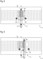
- the magnet arrangement 1.3 and the domain wall conductor 1.1 with the supporting magnet 1.6 behind it are shown as a schematic diagram in a first position relative to one another.
- the magnetic field should be represented by a large number of arrows.
- the domain walls W1, W2 are in the positions according to Figure 7 , where (as represented by the symbols) the first domain wall W1 is a so-called head-to-head domain wall and the second domain wall W2 is a so-called tail-to-tail domain wall.
- the magnetic field generated by the magnet arrangement 1.3 is relative to an axis Ax ( Figures 4 and 7 ), which runs parallel to the first direction x, is designed asymmetrically.
- the magnetic field 1.3 generated by the magnet arrangement is designed to be symmetrical with respect to an axis Ay, which runs parallel to a second direction.
- the second direction is oriented orthogonally to the first direction.
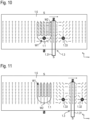
- the domain wall conductor 1.1 is shown in a further position, where the magnetic field is in the first position compared to the first position Direction x is shifted. Accordingly, the domain walls W1, W2 have changed their positions.
- the positions of the domain walls W1, W2 shifted further.
- the positions of the domain walls W1, W2 according to the Figure 11 include, for example, the information that the drum 2.1 or the component 2 compared to the arrangement of the Figure 7 has been moved so far that the magnet arrangement 1.3 has completely passed through the domain wall conductor 1.1, which is the case, for example, after completing a first revolution.
- the magnetic fields of the first and second magnets 1.32, 1.33 achieve a displacement of the domain walls W1, W2 across the second section 1.12, in which the domain wall conductor 1.1 runs in an arc with a relatively large radius.
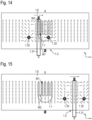
- the drum 2.1 or the component 2 should continue to rotate in the same direction (first direction x), accordingly in the Figures 12 to 15 Depending on the positioning of the magnet arrangement 1.3 relative to the domain wall conductor 1.1 or to the sensor element 1, different positions of the domain walls W1, W2 are shown.
- the domain wall W1 After each pass of the magnet arrangement 1.3 on the sensor element 1 or after each revolution of the component 2, the domain wall W1 has moved further to an adjacent first area A of the domain wall conductor 1.1. Accordingly, after each revolution, the domain wall W2 has moved further from a second area B to an adjacent second area B of the domain wall conductor 1.1 or is located there is in the second section 1.12, in which the domain wall conductor 1.1 runs in an arc with a relatively large radius. If the starting point is on the arc with the relatively large radius, the domain wall W2 is moved into an arc in the second region B. If an order is made in accordance with Figure 1 Correspondingly, five consecutive passes or revolutions in one direction could be counted.
- the magnetization directions within sections of the domain wall conductor 1.1 and thus the rough positions of the domain walls W1, W2 can be detected by the readout elements 3. In this way, it is possible to count revolutions or store the revolution information in an angle measuring device, even if no auxiliary energy can be used. This is important, for example, if a shaft is moved by weight during a power failure.
- the domain walls W1, W2 are also shifted depending on the direction of rotation, so that the sensor element 1 can be used reliably in applications that allow both directions of rotation.
- a magnetic field acts on the domain wall conductor 1.1 as the magnet arrangement 1.3 passes along the first direction x, the direction of which changes depending on the x position.
- Magnetic field lines on one side of the axis Ay ( Figure 7 ) have an opposite direction of rotation compared to magnetic field lines on the other side of one axis Ay.
- the magnetic field lines that cover areas A when crossing and the magnetic field lines that cover areas B when crossing have an opposite direction of rotation.
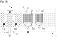
- a sensor element 1' can comprise several domain wall conductors 1.1, 1.1' in order to increase the number of countable revolutions, the domain wall conductors 1.1, 1.1' for example, each have a first domain wall W1, W1' and a second domain wall W2, W2'.
- the multiple domain wall conductors 1.1, 1.1' have different numbers of first sections 1.11, 1.11', in particular have different numbers of first areas A or have different numbers of second areas B.
- the numbers of the first areas A of the respective domain wall conductors 1.1, 1.1' are coprime.
- the multiple domain wall conductors 1.1, 1.1' can be arranged offset from one another in the first direction x or nested one inside the other.
- four domain wall conductors can be used with 7, 9, 11, 13 first areas A, so that 9009 (7 ⁇ 9 ⁇ 11 ⁇ 13) revolutions could then be counted.
- FIG 17 A third exemplary embodiment is shown, which is particularly suitable for applications in which only a few revolutions or runs have to be counted.
- the magnet arrangement 1.3" can be simplified so that it only has the first magnet 1.31 (see Figure 18 ) having.
- the first domain wall W1 cannot be pushed through the second section 1.12 of the domain wall conductor 1.1 with the aid of the magnetic field generated by the magnet arrangement 1.3".
- the countable number of revolutions or passes is therefore equal to the number of the first sections 1.11 of the domain wall conductor 1.1.
- the area with the large radius of curvature i.e. the second section of the domain wall conductor, could be omitted here, so that the domain wall conductor instead has two ends.
- the Magnetization can then be arranged there, for example, areas with antiferromagnetic coupling.
Landscapes
- Transmission And Conversion Of Sensor Element Output (AREA)
Applications Claiming Priority (2)
| Application Number | Priority Date | Filing Date | Title |
|---|---|---|---|
| DE102021205136.7A DE102021205136A1 (de) | 2021-05-20 | 2021-05-20 | Speichersystem mit einem sensorelement zur speicherung von umdrehungs- oder positionsinformationen |
| EP22156469.3A EP4092678B1 (fr) | 2021-05-20 | 2022-02-14 | Système mémoire doté d'un élément capteur destiné à la mémorisation des informations de rotation ou de position |
Related Parent Applications (2)
| Application Number | Title | Priority Date | Filing Date |
|---|---|---|---|
| EP22156469.3A Division EP4092678B1 (fr) | 2021-05-20 | 2022-02-14 | Système mémoire doté d'un élément capteur destiné à la mémorisation des informations de rotation ou de position |
| EP22156469.3A Division-Into EP4092678B1 (fr) | 2021-05-20 | 2022-02-14 | Système mémoire doté d'un élément capteur destiné à la mémorisation des informations de rotation ou de position |
Publications (3)
| Publication Number | Publication Date |
|---|---|
| EP4290188A2 true EP4290188A2 (fr) | 2023-12-13 |
| EP4290188A3 EP4290188A3 (fr) | 2024-03-20 |
| EP4290188B1 EP4290188B1 (fr) | 2024-12-04 |
Family
ID=80785235
Family Applications (3)
| Application Number | Title | Priority Date | Filing Date |
|---|---|---|---|
| EP23199586.1A Active EP4290189B1 (fr) | 2021-05-20 | 2022-02-14 | Système de stockage comprenant un élément de détection pour stocker des informations de rotation ou de position |
| EP22156469.3A Active EP4092678B1 (fr) | 2021-05-20 | 2022-02-14 | Système mémoire doté d'un élément capteur destiné à la mémorisation des informations de rotation ou de position |
| EP23199585.3A Active EP4290188B1 (fr) | 2021-05-20 | 2022-02-14 | Système de stockage comprenant un élément de détection pour stocker des informations de rotation ou de position |
Family Applications Before (2)
| Application Number | Title | Priority Date | Filing Date |
|---|---|---|---|
| EP23199586.1A Active EP4290189B1 (fr) | 2021-05-20 | 2022-02-14 | Système de stockage comprenant un élément de détection pour stocker des informations de rotation ou de position |
| EP22156469.3A Active EP4092678B1 (fr) | 2021-05-20 | 2022-02-14 | Système mémoire doté d'un élément capteur destiné à la mémorisation des informations de rotation ou de position |
Country Status (2)
| Country | Link |
|---|---|
| EP (3) | EP4290189B1 (fr) |
| DE (1) | DE102021205136A1 (fr) |
Families Citing this family (1)
| Publication number | Priority date | Publication date | Assignee | Title |
|---|---|---|---|---|
| DE102024001488A1 (de) * | 2024-05-07 | 2025-11-13 | Dr. Johannes Heidenhain Gmbh | Positionsmesseinrichtung |
Citations (3)
| Publication number | Priority date | Publication date | Assignee | Title |
|---|---|---|---|---|
| US4157591A (en) | 1976-08-10 | 1979-06-05 | U.S. Philips Corporation | Magnetic domain device |
| EP1740909B1 (fr) | 2004-04-24 | 2007-06-06 | HORST SIEDLE GmbH & Co. KG. | Element capteur destine a un compte-tours |
| US20100301842A1 (en) | 2007-08-27 | 2010-12-02 | Roland Mattheis | Magnetic revolution counter |
-
2021
- 2021-05-20 DE DE102021205136.7A patent/DE102021205136A1/de active Pending
-
2022
- 2022-02-14 EP EP23199586.1A patent/EP4290189B1/fr active Active
- 2022-02-14 EP EP22156469.3A patent/EP4092678B1/fr active Active
- 2022-02-14 EP EP23199585.3A patent/EP4290188B1/fr active Active
Patent Citations (3)
| Publication number | Priority date | Publication date | Assignee | Title |
|---|---|---|---|---|
| US4157591A (en) | 1976-08-10 | 1979-06-05 | U.S. Philips Corporation | Magnetic domain device |
| EP1740909B1 (fr) | 2004-04-24 | 2007-06-06 | HORST SIEDLE GmbH & Co. KG. | Element capteur destine a un compte-tours |
| US20100301842A1 (en) | 2007-08-27 | 2010-12-02 | Roland Mattheis | Magnetic revolution counter |
Also Published As
| Publication number | Publication date |
|---|---|
| DE102021205136A1 (de) | 2022-11-24 |
| EP4290188A3 (fr) | 2024-03-20 |
| EP4290189A3 (fr) | 2024-03-20 |
| EP4290189A2 (fr) | 2023-12-13 |
| EP4290189B1 (fr) | 2025-04-30 |
| EP4092678B1 (fr) | 2023-11-29 |
| EP4092678A1 (fr) | 2022-11-23 |
| EP4290188B1 (fr) | 2024-12-04 |
Similar Documents
| Publication | Publication Date | Title |
|---|---|---|
| EP3066421B1 (fr) | Capteur magnétique pour recensement absolu de rotations ou de distances lineaires | |
| EP1182461B2 (fr) | Capteur pour la détection de la direction d'un champs magnétique | |
| DE60200499T3 (de) | Stellungsfühler, besonders zur Feststellung von Verdrehung einer Lenksäule | |
| EP1597535B1 (fr) | Capteur magnetoresistif servant a determiner un angle ou une position | |
| EP2181308B1 (fr) | Compteur de tours à élément ferromagnétique | |
| EP0852700B1 (fr) | Systeme de detection sans contact de la position d'un objet et utilisation dudit dispositif | |
| DE102019206899A1 (de) | Dreherfassungsvorrichtung | |
| DE102019122188B4 (de) | Winkelsensorsystem | |
| DE102021006484A1 (de) | Magnetsensor | |
| EP4092678B1 (fr) | Système mémoire doté d'un élément capteur destiné à la mémorisation des informations de rotation ou de position | |
| EP4266007B1 (fr) | Élément de détection pour stocker des informations de rotation ou de position et système de stockage comprenant un élément de détection | |
| DE102025000739A1 (de) | Positionsmesseinrichtung | |
| EP3924694B1 (fr) | Dispositif capteur et son procédé de fonctionnement | |
| EP0867692B1 (fr) | Dispositif de détection sans contact de la position d'un objet et utilisation dudit dispositif | |
| EP3828508B1 (fr) | Élément de capteur permettant d'enregistrer des informations de rotation ou de position | |
| DE102005061347A1 (de) | Anordnung zur Messung des absoluten Drehwinkels einer Welle | |
| WO1999030111A1 (fr) | Dispositif de mesure pour determiner sans contact un angle de rotation | |
| DE102023102164B4 (de) | Sekundärspulenanordnung für einen induktiven Encoder | |
| DE112014003316B4 (de) | Rotationssensor | |
| DE10127754B4 (de) | Magnetoresistive Schichtanordnung | |
| WO2018202239A1 (fr) | Dispositif capteur et procédé de production d'une séquence de signaux de changement de position | |
| DE102016010332A1 (de) | Vorrichtung mit einem Geber und einem Sensor | |
| EP4650719A1 (fr) | Dispositif magnétique de mesure d'angle | |
| DE10206544A1 (de) | Getriebe sowie mit diesem Getriebe ausgestatteter Drehgeber | |
| DE102024001488A1 (de) | Positionsmesseinrichtung |
Legal Events
| Date | Code | Title | Description |
|---|---|---|---|
| PUAI | Public reference made under article 153(3) epc to a published international application that has entered the european phase |
Free format text: ORIGINAL CODE: 0009012 |
|
| STAA | Information on the status of an ep patent application or granted ep patent |
Free format text: STATUS: REQUEST FOR EXAMINATION WAS MADE |
|
| 17P | Request for examination filed |
Effective date: 20230926 |
|
| AC | Divisional application: reference to earlier application |
Ref document number: 4092678 Country of ref document: EP Kind code of ref document: P |
|
| AK | Designated contracting states |
Kind code of ref document: A2 Designated state(s): AL AT BE BG CH CY CZ DE DK EE ES FI FR GB GR HR HU IE IS IT LI LT LU LV MC MK MT NL NO PL PT RO RS SE SI SK SM TR |
|
| RAP3 | Party data changed (applicant data changed or rights of an application transferred) |
Owner name: DR. JOHANNES HEIDENHAIN GMBH |
|
| REG | Reference to a national code |
Ref country code: DE Ref legal event code: R079 Free format text: PREVIOUS MAIN CLASS: G01D0005140000 Ipc: G11C0019080000 Ref document number: 502022002331 Country of ref document: DE |
|
| PUAL | Search report despatched |
Free format text: ORIGINAL CODE: 0009013 |
|
| AK | Designated contracting states |
Kind code of ref document: A3 Designated state(s): AL AT BE BG CH CY CZ DE DK EE ES FI FR GB GR HR HU IE IS IT LI LT LU LV MC MK MT NL NO PL PT RO RS SE SI SK SM TR |
|
| RIC1 | Information provided on ipc code assigned before grant |
Ipc: G01D 5/14 20060101ALI20240214BHEP Ipc: G11C 19/08 20060101AFI20240214BHEP |
|
| GRAP | Despatch of communication of intention to grant a patent |
Free format text: ORIGINAL CODE: EPIDOSNIGR1 |
|
| STAA | Information on the status of an ep patent application or granted ep patent |
Free format text: STATUS: GRANT OF PATENT IS INTENDED |
|
| INTG | Intention to grant announced |
Effective date: 20240826 |
|
| GRAS | Grant fee paid |
Free format text: ORIGINAL CODE: EPIDOSNIGR3 |
|
| RBV | Designated contracting states (corrected) |
Designated state(s): AL AT BE BG CH CY CZ DE DK EE ES FI FR GB GR HR HU IE IS IT LI LT LU LV MC MK MT NL NO PL PT RO RS SE SI SK SM TR |
|
| GRAA | (expected) grant |
Free format text: ORIGINAL CODE: 0009210 |
|
| STAA | Information on the status of an ep patent application or granted ep patent |
Free format text: STATUS: THE PATENT HAS BEEN GRANTED |
|
| AC | Divisional application: reference to earlier application |
Ref document number: 4092678 Country of ref document: EP Kind code of ref document: P |
|
| AK | Designated contracting states |
Kind code of ref document: B1 Designated state(s): AL AT BE BG CH CY CZ DE DK EE ES FI FR GB GR HR HU IE IS IT LI LT LU LV MC MK MT NL NO PL PT RO RS SE SI SK SM TR |
|
| REG | Reference to a national code |
Ref country code: CH Ref legal event code: EP |
|
| REG | Reference to a national code |
Ref country code: DE Ref legal event code: R096 Ref document number: 502022002331 Country of ref document: DE |
|
| REG | Reference to a national code |
Ref country code: IE Ref legal event code: FG4D Free format text: LANGUAGE OF EP DOCUMENT: GERMAN |
|
| REG | Reference to a national code |
Ref country code: LT Ref legal event code: MG9D |
|
| REG | Reference to a national code |
Ref country code: NL Ref legal event code: MP Effective date: 20241204 |
|
| PG25 | Lapsed in a contracting state [announced via postgrant information from national office to epo] |
Ref country code: HR Free format text: LAPSE BECAUSE OF FAILURE TO SUBMIT A TRANSLATION OF THE DESCRIPTION OR TO PAY THE FEE WITHIN THE PRESCRIBED TIME-LIMIT Effective date: 20241204 |
|
| PG25 | Lapsed in a contracting state [announced via postgrant information from national office to epo] |
Ref country code: FI Free format text: LAPSE BECAUSE OF FAILURE TO SUBMIT A TRANSLATION OF THE DESCRIPTION OR TO PAY THE FEE WITHIN THE PRESCRIBED TIME-LIMIT Effective date: 20241204 |
|
| PG25 | Lapsed in a contracting state [announced via postgrant information from national office to epo] |
Ref country code: BG Free format text: LAPSE BECAUSE OF FAILURE TO SUBMIT A TRANSLATION OF THE DESCRIPTION OR TO PAY THE FEE WITHIN THE PRESCRIBED TIME-LIMIT Effective date: 20241204 |
|
| PG25 | Lapsed in a contracting state [announced via postgrant information from national office to epo] |
Ref country code: ES Free format text: LAPSE BECAUSE OF FAILURE TO SUBMIT A TRANSLATION OF THE DESCRIPTION OR TO PAY THE FEE WITHIN THE PRESCRIBED TIME-LIMIT Effective date: 20241204 |
|
| PG25 | Lapsed in a contracting state [announced via postgrant information from national office to epo] |
Ref country code: NO Free format text: LAPSE BECAUSE OF FAILURE TO SUBMIT A TRANSLATION OF THE DESCRIPTION OR TO PAY THE FEE WITHIN THE PRESCRIBED TIME-LIMIT Effective date: 20250304 |
|
| PG25 | Lapsed in a contracting state [announced via postgrant information from national office to epo] |
Ref country code: GR Free format text: LAPSE BECAUSE OF FAILURE TO SUBMIT A TRANSLATION OF THE DESCRIPTION OR TO PAY THE FEE WITHIN THE PRESCRIBED TIME-LIMIT Effective date: 20250305 Ref country code: LV Free format text: LAPSE BECAUSE OF FAILURE TO SUBMIT A TRANSLATION OF THE DESCRIPTION OR TO PAY THE FEE WITHIN THE PRESCRIBED TIME-LIMIT Effective date: 20241204 |
|
| PG25 | Lapsed in a contracting state [announced via postgrant information from national office to epo] |
Ref country code: RS Free format text: LAPSE BECAUSE OF FAILURE TO SUBMIT A TRANSLATION OF THE DESCRIPTION OR TO PAY THE FEE WITHIN THE PRESCRIBED TIME-LIMIT Effective date: 20250304 |
|
| PG25 | Lapsed in a contracting state [announced via postgrant information from national office to epo] |
Ref country code: NL Free format text: LAPSE BECAUSE OF FAILURE TO SUBMIT A TRANSLATION OF THE DESCRIPTION OR TO PAY THE FEE WITHIN THE PRESCRIBED TIME-LIMIT Effective date: 20241204 |
|
| PG25 | Lapsed in a contracting state [announced via postgrant information from national office to epo] |
Ref country code: SM Free format text: LAPSE BECAUSE OF FAILURE TO SUBMIT A TRANSLATION OF THE DESCRIPTION OR TO PAY THE FEE WITHIN THE PRESCRIBED TIME-LIMIT Effective date: 20241204 |
|
| PG25 | Lapsed in a contracting state [announced via postgrant information from national office to epo] |
Ref country code: PL Free format text: LAPSE BECAUSE OF FAILURE TO SUBMIT A TRANSLATION OF THE DESCRIPTION OR TO PAY THE FEE WITHIN THE PRESCRIBED TIME-LIMIT Effective date: 20241204 |
|
| PG25 | Lapsed in a contracting state [announced via postgrant information from national office to epo] |
Ref country code: IS Free format text: LAPSE BECAUSE OF FAILURE TO SUBMIT A TRANSLATION OF THE DESCRIPTION OR TO PAY THE FEE WITHIN THE PRESCRIBED TIME-LIMIT Effective date: 20250404 |
|
| PG25 | Lapsed in a contracting state [announced via postgrant information from national office to epo] |
Ref country code: PT Free format text: LAPSE BECAUSE OF FAILURE TO SUBMIT A TRANSLATION OF THE DESCRIPTION OR TO PAY THE FEE WITHIN THE PRESCRIBED TIME-LIMIT Effective date: 20250404 |
|
| PG25 | Lapsed in a contracting state [announced via postgrant information from national office to epo] |
Ref country code: EE Free format text: LAPSE BECAUSE OF FAILURE TO SUBMIT A TRANSLATION OF THE DESCRIPTION OR TO PAY THE FEE WITHIN THE PRESCRIBED TIME-LIMIT Effective date: 20241204 |
|
| PG25 | Lapsed in a contracting state [announced via postgrant information from national office to epo] |
Ref country code: RO Free format text: LAPSE BECAUSE OF FAILURE TO SUBMIT A TRANSLATION OF THE DESCRIPTION OR TO PAY THE FEE WITHIN THE PRESCRIBED TIME-LIMIT Effective date: 20241204 |
|
| PG25 | Lapsed in a contracting state [announced via postgrant information from national office to epo] |
Ref country code: SK Free format text: LAPSE BECAUSE OF FAILURE TO SUBMIT A TRANSLATION OF THE DESCRIPTION OR TO PAY THE FEE WITHIN THE PRESCRIBED TIME-LIMIT Effective date: 20241204 |
|
| REG | Reference to a national code |
Ref country code: DE Ref legal event code: R097 Ref document number: 502022002331 Country of ref document: DE |
|
| PG25 | Lapsed in a contracting state [announced via postgrant information from national office to epo] |
Ref country code: SE Free format text: LAPSE BECAUSE OF FAILURE TO SUBMIT A TRANSLATION OF THE DESCRIPTION OR TO PAY THE FEE WITHIN THE PRESCRIBED TIME-LIMIT Effective date: 20241204 |
|
| PG25 | Lapsed in a contracting state [announced via postgrant information from national office to epo] |
Ref country code: MC Free format text: LAPSE BECAUSE OF FAILURE TO SUBMIT A TRANSLATION OF THE DESCRIPTION OR TO PAY THE FEE WITHIN THE PRESCRIBED TIME-LIMIT Effective date: 20241204 |
|
| PG25 | Lapsed in a contracting state [announced via postgrant information from national office to epo] |
Ref country code: DK Free format text: LAPSE BECAUSE OF FAILURE TO SUBMIT A TRANSLATION OF THE DESCRIPTION OR TO PAY THE FEE WITHIN THE PRESCRIBED TIME-LIMIT Effective date: 20241204 |
|
| PLBE | No opposition filed within time limit |
Free format text: ORIGINAL CODE: 0009261 |
|
| STAA | Information on the status of an ep patent application or granted ep patent |
Free format text: STATUS: NO OPPOSITION FILED WITHIN TIME LIMIT |
|
| PG25 | Lapsed in a contracting state [announced via postgrant information from national office to epo] |
Ref country code: LU Free format text: LAPSE BECAUSE OF NON-PAYMENT OF DUE FEES Effective date: 20250214 |
|
| REG | Reference to a national code |
Ref country code: CH Ref legal event code: L10 Free format text: ST27 STATUS EVENT CODE: U-0-0-L10-L00 (AS PROVIDED BY THE NATIONAL OFFICE) Effective date: 20251015 |
|
| 26N | No opposition filed |
Effective date: 20250905 |
|
| REG | Reference to a national code |
Ref country code: BE Ref legal event code: MM Effective date: 20250228 |
|
| REG | Reference to a national code |
Ref country code: CH Ref legal event code: R17 Free format text: ST27 STATUS EVENT CODE: U-0-0-R10-R17 (AS PROVIDED BY THE NATIONAL OFFICE) Effective date: 20260108 |
|
| PG25 | Lapsed in a contracting state [announced via postgrant information from national office to epo] |
Ref country code: FR Free format text: LAPSE BECAUSE OF NON-PAYMENT OF DUE FEES Effective date: 20250228 |
|
| PG25 | Lapsed in a contracting state [announced via postgrant information from national office to epo] |
Ref country code: BE Free format text: LAPSE BECAUSE OF NON-PAYMENT OF DUE FEES Effective date: 20250228 |
|
| REG | Reference to a national code |
Ref country code: CH Ref legal event code: U11 Free format text: ST27 STATUS EVENT CODE: U-0-0-U10-U11 (AS PROVIDED BY THE NATIONAL OFFICE) Effective date: 20260301 |
|
| PGFP | Annual fee paid to national office [announced via postgrant information from national office to epo] |
Ref country code: GB Payment date: 20260220 Year of fee payment: 5 |
|
| PGFP | Annual fee paid to national office [announced via postgrant information from national office to epo] |
Ref country code: IE Payment date: 20260218 Year of fee payment: 5 Ref country code: DE Payment date: 20260218 Year of fee payment: 5 |
|
| PGFP | Annual fee paid to national office [announced via postgrant information from national office to epo] |
Ref country code: AT Payment date: 20260301 Year of fee payment: 5 |
|
| PGFP | Annual fee paid to national office [announced via postgrant information from national office to epo] |
Ref country code: IT Payment date: 20260224 Year of fee payment: 5 |
|
| PGFP | Annual fee paid to national office [announced via postgrant information from national office to epo] |
Ref country code: CH Payment date: 20260301 Year of fee payment: 5 Ref country code: CZ Payment date: 20260212 Year of fee payment: 5 |