EP4290196A1 - Système et procédé de surveillance de vibration - Google Patents
Système et procédé de surveillance de vibration Download PDFInfo
- Publication number
- EP4290196A1 EP4290196A1 EP22178177.6A EP22178177A EP4290196A1 EP 4290196 A1 EP4290196 A1 EP 4290196A1 EP 22178177 A EP22178177 A EP 22178177A EP 4290196 A1 EP4290196 A1 EP 4290196A1
- Authority
- EP
- European Patent Office
- Prior art keywords
- target
- vibration
- targets
- data
- measurement unit
- Prior art date
- Legal status (The legal status is an assumption and is not a legal conclusion. Google has not performed a legal analysis and makes no representation as to the accuracy of the status listed.)
- Pending
Links
- 238000012544 monitoring process Methods 0.000 title claims abstract description 98
- 238000000034 method Methods 0.000 title claims description 23
- 238000005259 measurement Methods 0.000 claims abstract description 96
- 238000012545 processing Methods 0.000 claims abstract description 37
- 238000003384 imaging method Methods 0.000 claims abstract description 23
- 230000000007 visual effect Effects 0.000 claims abstract description 12
- 230000009466 transformation Effects 0.000 claims description 16
- 238000000926 separation method Methods 0.000 claims description 6
- 238000011156 evaluation Methods 0.000 claims description 4
- 238000009434 installation Methods 0.000 description 7
- 230000008569 process Effects 0.000 description 5
- 230000009286 beneficial effect Effects 0.000 description 4
- 230000005540 biological transmission Effects 0.000 description 2
- 230000008859 change Effects 0.000 description 2
- 238000010586 diagram Methods 0.000 description 2
- 238000006073 displacement reaction Methods 0.000 description 2
- 238000000691 measurement method Methods 0.000 description 2
- 238000009826 distribution Methods 0.000 description 1
- 238000004519 manufacturing process Methods 0.000 description 1
- 239000011159 matrix material Substances 0.000 description 1
- 238000012986 modification Methods 0.000 description 1
- 230000004048 modification Effects 0.000 description 1
- 238000005457 optimization Methods 0.000 description 1
- 238000001228 spectrum Methods 0.000 description 1
- 239000000126 substance Substances 0.000 description 1
- 230000001131 transforming effect Effects 0.000 description 1
- 230000035899 viability Effects 0.000 description 1
Images



Classifications
-
- G—PHYSICS
- G01—MEASURING; TESTING
- G01H—MEASUREMENT OF MECHANICAL VIBRATIONS OR ULTRASONIC, SONIC OR INFRASONIC WAVES
- G01H9/00—Measuring mechanical vibrations or ultrasonic, sonic or infrasonic waves by using radiation-sensitive means, e.g. optical means
-
- G—PHYSICS
- G01—MEASURING; TESTING
- G01H—MEASUREMENT OF MECHANICAL VIBRATIONS OR ULTRASONIC, SONIC OR INFRASONIC WAVES
- G01H3/00—Measuring characteristics of vibrations by using a detector in a fluid
- G01H3/10—Amplitude; Power
- G01H3/12—Amplitude; Power by electric means
- G01H3/125—Amplitude; Power by electric means for representing acoustic field distribution
-
- G—PHYSICS
- G01—MEASURING; TESTING
- G01M—TESTING STATIC OR DYNAMIC BALANCE OF MACHINES OR STRUCTURES; TESTING OF STRUCTURES OR APPARATUS, NOT OTHERWISE PROVIDED FOR
- G01M7/00—Vibration-testing of structures; Shock-testing of structures
Definitions
- the present invention relates to a vibration monitoring system and method.
- Vibration monitoring of various installations is used to obtain indications of the state of a process or the installations themselves.
- US 2011/0288796 To overcome drawbacks of installations with permanently mounted accelerometers, it has been proposed in US 2011/0288796 to use one or more radar-based displacement sensors to gather vibration information from an operating machine.
- the radar-based displacement sensor may be steered or directed toward multiple regions of interest on the operating machine to gather vibration information from the multiple regions of interest.
- a general object of the present invention is thus to provide for improved vibration monitoring, in particular allowing an improved user experience of the vibration monitoring.
- a vibration monitoring system for remote monitoring of vibration of each target in a plurality of targets
- the vibration monitoring system comprising: a measurement unit configured to perform contactless measurement of vibration of each target in the plurality of targets; and processing circuitry coupled to the measurement unit and an imaging unit, and configured to: acquire, from the measurement unit, vibration data for each target in the plurality of targets; acquire, from the imaging unit, an image of a scene including each target in the plurality of targets; determine a vibration monitoring data structure based on a target position of each target in the plurality of targets, the vibration data for each target in the plurality of targets, the image, and a coordinate transformation between a coordinate system of the scene, in which the target position of each target in the plurality of targets is defined, and a coordinate system of the image; and provide the vibration monitoring data structure to a remote device, allowing display at the remote device of a visual representation of the scene including each target in the plurality of targets, and a representation of the vibration data for each target
- the present invention is based on the realization that a correlation between an image of the monitored scene and vibration data for targets in the scene can be used to display a visual representation of the scene at a remote location, where the visual representation includes each target and a representation of the vibration data for each target.
- a user or operator can get an overview of the scene, as well as an indication of the vibration status of each of a plurality of targets in the scene from a remote and safe location.
- This provides for improved monitoring of the status of an installation, which may be beneficial for safety as well as for optimization of any process performed at the installation.
- the vibration monitoring system may comprise the imaging unit; the imaging unit may be in a fixed positional arrangement in relation to the measurement unit; and the coordinate transformation may be predefined and stored in memory included in the vibration monitoring system.
- This configuration of the vibration monitoring system may facilitate installation, since the will be no need to perform the coordinate transformation after installation. Furthermore, the user may be able to see, for example during setup of the vibration monitoring system, an image of the scene within which the measurement unit is capable of performing contactless measurement of vibration.
- the processing circuitry of the vibration monitoring system may be configured to receive, from the remote device, a signal indicating a request for remote monitoring of vibration of an additional target at an additional target position in the scene; acquire, from the measurement unit, vibration data for the additional target; determine an expanded vibration monitoring data structure additionally based on the vibration data for the additional target; and provide the expanded vibration monitoring data structure to the remote device.
- the additional target and/or other potential additional targets may be checked for viability of vibration measurement following the request for monitoring.
- potential targets may be pre-qualified, and a visual indication of accessible targets, where reliable vibration monitoring can be performed, may be displayed to the user.
- the measurement unit may advantageously comprise a transceiver for generating, transmitting and receiving electromagnetic signals; an antenna arrangement coupled to the transceiver for radiating at least one electromagnetic transmit signal generated by the transceiver towards each target in the plurality of targets, and for returning electromagnetic reflection signals resulting from reflection of the at least one transmit signal at each target in the plurality of targets back towards the transceiver; and processing circuitry coupled to the transceiver and configured to determine the vibration data for each target in the plurality of targets based on a timing relation between the at least one transmit signal and the reflection signals.
- the measurement unit may be configured to only radiate the at least one transmit signal towards each target in the plurality of targets, and not to positions between the selected targets.
- the transceiver of the measurement unit may be configured to form a plurality of measurement signals, each measurement signal in the plurality of measurement signals being based on the at least one transmit signal and the reflection signal resulting from reflection at a respective target in the plurality of targets, the measurement signal being indicative of at least a phase difference between the at least one transmit signal and the reflection signal; and the processing circuitry may be configured to determine the vibration data for each target position in the plurality of target positions based on the measurement signal in the plurality of measurement signals corresponding to the target position.
- Analysis of the phase difference between the reflection signal and the transmit signal can provide considerably higher accuracy (in the order of 10 ⁇ m or better for typical frequency ranges and measurement sweep configurations) than analysis of the frequency difference between the reflection signal and the transmit signal (in the order of 1 mm for typical frequency ranges and measurement sweep configurations).
- CW continuous wave
- FMCW frequency modulated continuous wave
- radar systems are, per se , well-known to one of ordinary skill in the art.
- phase information is generally not used because the relation between the phase information and distance is not unambiguous for typical distance ranges.
- the present inventors have now found that the more accurate phase difference measurement can yield unambiguous measurement results for the vibration monitoring system according to embodiments of the present invention, due to the much smaller measurement range required.
- a method of remote vibration monitoring comprising the steps of: acquiring, from a measurement unit configured to perform contactless vibration measurements, vibration data for each target in a plurality of targets; acquiring, from an imaging unit, an image of a scene including each target in the plurality of targets; determining a vibration monitoring data structure based on a target position of each target in the plurality of targets, the vibration data for each target in the plurality of targets, the image, and a coordinate transformation between a coordinate system of the scene, in which the target position of each target in the plurality of targets is defined, and a coordinate system of the image; and providing the vibration monitoring data structure to a remote device, allowing display at the remote device of a visual representation of the scene including each target in the plurality of targets, and a representation of the vibration data for each target in the plurality of targets.
- the present invention thus relates to a vibration monitoring system
- a vibration monitoring system comprising a measurement unit and processing circuitry coupled to the measurement unit and an imaging unit, and configured to: acquire, from the measurement unit, vibration data for each target in the plurality of targets; acquire, from an imaging unit, an image of a scene including each target in the plurality of targets; determine a vibration monitoring data structure; and provide the vibration monitoring data structure to a remote device, allowing display at the remote device of a visual representation of the scene including each target in the plurality of targets, and a representation of the vibration data for each target in the plurality of targets.
- Fig 1 schematically shows an example embodiment of the vibration monitoring system 1 according to the present invention arranged for remote monitoring of vibration in the exemplary setting of a process facility 3, which may, for example, be a factory for manufacturing chemicals.
- a process facility 3 which may, for example, be a factory for manufacturing chemicals.
- the exemplary setting of fig 1 represents one example only of various possible and beneficial uses of embodiments of the vibration monitoring system according to the present invention.
- Other examples include, for example, vibration monitoring of machinery, buildings, structures, etc.
- the process facility 3 in fig 1 may serve as an illustrative example of a setting where the contactless vibration measurement and remote monitoring provided by the vibration monitoring system according to embodiments of the present invention may be particularly beneficial.
- vibration of each target T n in a plurality of targets in a scene 5 is monitored remotely, using contactless measurement.
- a vibration monitoring data structure is provided to a remote device 7, to allow display to a user 9 of a visual representation of the scene 5, including the targets T n and a representation of vibration data for each target T n .
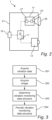
- Fig 2 is a schematic block diagram of an example configuration of the vibration monitoring system 1 in fig 1 .
- the vibration monitoring system 1 comprises a measurement unit 11, an imaging unit 13, processing circuitry 15 including non-volatile memory 17, an interface 19, and a housing 21.
- the vibration monitoring system 1 may thus comprise an imaging unit 13, and the imaging unit 13 may be in a fixed positional arrangement in relation to the measurement unit 11.
- Information about a relation between the monitored scene 5 and an image captured by the imaging unit 13 may be stored in the memory 17, which is here exemplified as being included in the processing circuitry 15.
- This information may include a coordinate transformation between a coordinate system of the scene 5 and a coordinate system of the image.
- This configuration is expected to be user-friendly, with a simple and straightforward setup procedure, and it is also beneficial that the measurement unit 11 and the imaging unit 13 "see" the same scene 5 if the vibration monitoring system 1 is moved and/or if it is desired to monitor vibration of another scene.
- the imaging unit 13 need not necessarily be included in the vibration monitoring system 1. Also, even if included in the vibration monitoring system 1, the imaging unit 13 need not be in a fixed positional arrangement in relation to the measurement unit 11 or enclosed in the same housing 21 as the measurement unit 11. Since live images may generally not be needed, it may be sufficient to take an image during setup of the vibration monitoring system 1, for example. A coordinate transformation between the coordinate system of the scene 5 and the coordinate system of the image can then be determined using per se known image processing techniques.
- fig 2 indicates that the vibration monitoring system 1 comprises processing circuitry 15 arranged inside the same housing 21 as the measurement unit 11 and the imaging unit 13, it should be understood that the processing circuitry 15 of the vibration monitoring system 1 need not be co-located with the measurement unit 11, but that part of, or all, the processing required may take place at another location or may be distributed. For example, processing may take place in the cloud and/or in the remote device 7.
- the measurement unit 11 may comprise a transceiver 23, an antenna arrangement 25, and a measurement processor 27.
- the transceiver 23 may be configured to generate, transmit, and receive electromagnetic signals, preferably with a carrier frequency higher than 40 GHz, such as higher than 70 GHz.
- the antenna arrangement 25, here exemplified as a lens antenna for high frequencies, is coupled to the transceiver 23 for radiating at least one electromagnetic transmit signal S T (referring to fig 1 ) generated by the transceiver 23 towards each target T n in the plurality of targets and for receiving and returning to the transceiver 23 electromagnetic reflection signals S R,n resulting from reflection of the at least one transmit signal S T at each target T n .
- the measurement processor 27 is coupled to the transceiver 23 and configured to determine vibration data V n for each target T n based on a timing relation between the at least one transmit signal S T and the reflection signals S R,n .
- the vibration data may, for example, be based on an amplitude and frequency spectrum of changes over time of distances between the measurement unit 11 and each target T n .
- the above-described radar-based measurement unit 11 may advantageously be implemented using a so-called monolithic microwave integrated circuit (MMIC) for realizing the transceiver 23.
- MMIC monolithic microwave integrated circuit
- phase-based processing may be used, rather than frequency-based processing.
- the transmit signal S T and the reflection signal S R,n from reflection of the transmit signal S T at a target T n may first be combined to form the so-called intermediate frequency signal S IF , using techniques that are per se well-known in the art of FMCW-type radar level gauge systems.
- a phase ⁇ of the intermediate frequency signal S IF may be determined. According to embodiments of the invention, this may be done by transforming the intermediate frequency signal S IF to the frequency domain, for example using FFT, identifying the frequency corresponding to reflection at the particular target T n , and determining the phase ⁇ of the intermediate frequency signal S IF for this frequency. For the small changes in distance resulting from vibration, the change of the phase can be used to unambiguously determine the change in distance with high accuracy.
- a single transmit signal S T with a wide lobe may be transmitted towards the entire scene 5, and the reflection signals S R,n resulting from reflection of the transmit signal S T at the individual targets T n may be evaluated.
- the radar-based measurement unit 11 may be provided with a transceiver 23 and an antenna arrangement 25 that allows transmission of one transmit signal S T,n for each individual target T n .
- Such a targeted transmit signal may have a narrow lobe, an allows for more efficient use of the radiated energy.
- only pre-selected targets T n need to be radiated with microwave energy.
- An antenna arrangement 25 that allows transmission of one transmit signal S T,n for each individual target T n may, for example, comprise a plurality of individual antennas and/or one or more antennas - for example patch antennas - with steerable lobes.
- vibration monitoring system 1 may be advantageous for many applications, such as involving hot or cold surfaces or hazy or smoky environments
- a radar-based measurement unit 11 such as that described above
- the vibration monitoring system 1 is not limited to any particular contactless measurement technique, and that it is foreseen that, for example, a laser-based measurement unit may be included in the vibration monitoring system 1 according to embodiments of the invention.
- the schematic illustration in fig 1 indicates contactless measurement of vibration of each target T n from a single viewpoint.
- This setup allows measurement of the vibration along a straight line between the single viewpoint (that may be represented by the base of the arrow at the vibration monitoring system 1 in fig 1 ) and each target T n .
- vibration in additional directions can be measured and added to the vibration monitoring data structure.
- one additional viewpoint may be displaced in the vertical direction in fig 1 and one additional viewpoint may be displaced in a horizontal direction that is different from (such as substantially perpendicular to) the above-mentioned straight line.
- the second additional viewpoint may be displaced along the wall in fig 1 . This configuration will allow determination of vibration of each target T n in any direction.
- the measurement unit 11 may be configured to perform contactless measurement of a distance to each target T n in the plurality of targets; and the processing circuitry 15 may be configured to acquire, from the measurement unit 11, distance data for each target T n in the plurality of targets; determine, based on the distance data, deformation data for each target T n in the plurality of targets; and provide the deformation data for at least one target T n in the plurality of targets to the remote device 7.
- the processing circuitry 15 may optionally be configured to acquire distance data indicative of the distance to at least one reference target, such as a reflector arranged on a wall or other structure, which can be expected not to be deformed or displaced.
- Fig 4 is a schematic illustration of an embodiment of the vibration monitoring system 1 of the invention, which mainly differs from that in fig 1 in that the processing circuitry 15 is provided as a cloud-solution, so that processing takes place remotely.
- vibration data is acquired, by the processing circuitry 15 from a measurement unit 11 configured to perform contactless vibration measurements.
- the acquired vibration data is for each target T n in the plurality of targets in the scene 5.
- a second step 302 which can take place before, after or at the same time as the first step 301, an image is acquired, by the processing circuitry 15 from an imaging unit 13 arranged to capture images of the scene 5 including each target T n in the plurality of targets.
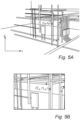
- a vibration monitoring data structure is determined. Additionally referring to figs 5A-B , the vibration monitoring data structure is based on a target position (x n , y n ) of each target T n in the plurality of targets, the above-mentioned vibration data V n for each target T n in the plurality of targets, the image of the scene 5, and a coordinate transformation between a coordinate system of the scene 5 (see fig 5A ), in which the target position (x n , y n ) of each target Tn is defined, and a coordinate system of the image (see fig 5B ).
- fig 5A illustrates a coordinate system of the scene 5 in the process facility 3
- fig 5B illustrates a coordinate system of the image of the scene 5.
- each target T n has a corresponding coordinate (x n , y n ). Since the scene 5 is three-dimensional, each target T n actually has a position in space (x n , y n , z n ), but due to the two-dimensional nature of the image, the coordinate transformation is between a two-dimensional projection of the scene 5 and the image.
- the third dimension - the depth - may advantageously be used to enhance the capability of the measurement unit to distinguish between targets T n .
- a radar-based measurement unit 11 such as described above can conveniently distinguish between reflection signals resulting from reflection at different targets based on different distances between the measurement unit 11 and the targets.
- the coordinates (x n , y n ) of the targets T n in the scene 5 have been transformed to corresponding coordinates ( ⁇ n , ⁇ n ) in the coordinate system of the image.
- This coordinate transformation may, for instance, take the form of a coordinate transformation matrix, as is well-known to those skilled in the relevant art.
- the application of the coordinate transformation, to transform the target coordinates (x n , y n ) to the corresponding image coordinates ( ⁇ n , ⁇ n ) may, for example, take place at the measurement site (as shown in fig 1 ), in the cloud (as shown in fig 4 ), or at the remote device 7.
- the vibration monitoring data structure is provided to the remote device 7, to allow display at the remote device 7 of a visual representation of the scene 5, including each target T n and a representation of the vibration data V n for each target T n .
- the vibration monitoring data structure may be provided at one time as one data set. Alternatively, the vibration monitoring data structure may be provided as several partial data sets, at different points in time.
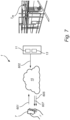
- Fig 7 is a schematic illustration of an embodiment of the vibration monitoring system 1 of the invention, which mainly differs from that in fig 1 in that the processing circuitry 15 is provided as a cloud-solution, so that processing takes place remotely.
- a request is received, by the processing circuitry 15, from the remote device 7 for remote monitoring of vibration of an additional target T m at an additional target position (x m , y m ) in the scene 5.
- the request may specify the target position in terms of coordinates ( ⁇ m , ⁇ m ) in the image coordinate system, and coordinate transformation may be performed by the processing circuitry 15.
- the request may, for example, be initiated by the user 9 selecting a location in the image of the scene 5 displayed at the remote device 7.
- the processing circuitry 15 acquires, from the measurement unit 11, vibration data V m for the additional target position Tm.
- vibration data encompasses any data that may be used to provide information about the vibration of a given target. Accordingly, the vibration data may convey information about a position in space of the target T m , a signal amplitude, a signal frequency distribution, etc.
- the vibration data V m may optionally be evaluated, in step 603.
- the evaluation may be in view of at least one predefined criterion relating to signal strength and/or spatial separation in relation to vibration data for at least one other target T n in the plurality of targets.
- the spatial separation may be in the three-dimensional space of the scene 5, so that targets that appear very close to each other in the image can be separated due to their separation in the depth dimension (z).
- step 604 If it is determined in step 604 that the result of the evaluation of step 603 was that the vibration data for the additional target T m failed to fulfil the at least one predefined criterion (N), an indication is provided in step 605, by the processing circuitry 15 to the remote device 7, that remote monitoring of vibration of the additional target T m cannot be performed.
- This conclusion may be arrived at, by the processing circuitry 15, if, for example, the amplitude of signals reflected by the additional target T m is lower than a predefined threshold amplitude and/or if it is determined that a distance in space between the additional target T m and the closest one of the existing targets is shorter than a predefined threshold distance.
- the user 9 may request monitoring of another target, as is schematically indicated in fig 6 .
- an expanded vibration monitoring data structure is determined in step 606, by the processing circuitry.
- the expanded vibration monitoring data structure is additionally based on the vibration data V m for the additional target T m .
- the expanded vibration monitoring data structure is provided to the remote device 7 for display of the additional target in the representation of the scene 5.
- the transmit signal could be a pulsed signal.
Landscapes
- Physics & Mathematics (AREA)
- General Physics & Mathematics (AREA)
- Engineering & Computer Science (AREA)
- Acoustics & Sound (AREA)
- Radar, Positioning & Navigation (AREA)
- Remote Sensing (AREA)
- Measurement Of Mechanical Vibrations Or Ultrasonic Waves (AREA)
Priority Applications (3)
| Application Number | Priority Date | Filing Date | Title |
|---|---|---|---|
| EP22178177.6A EP4290196A1 (fr) | 2022-06-09 | 2022-06-09 | Système et procédé de surveillance de vibration |
| US18/325,429 US20230400348A1 (en) | 2022-06-09 | 2023-05-30 | Vibration monitoring system and method |
| CN202310665382.9A CN117213607A (zh) | 2022-06-09 | 2023-06-06 | 振动监测系统和方法 |
Applications Claiming Priority (1)
| Application Number | Priority Date | Filing Date | Title |
|---|---|---|---|
| EP22178177.6A EP4290196A1 (fr) | 2022-06-09 | 2022-06-09 | Système et procédé de surveillance de vibration |
Publications (1)
| Publication Number | Publication Date |
|---|---|
| EP4290196A1 true EP4290196A1 (fr) | 2023-12-13 |
Family
ID=82016514
Family Applications (1)
| Application Number | Title | Priority Date | Filing Date |
|---|---|---|---|
| EP22178177.6A Pending EP4290196A1 (fr) | 2022-06-09 | 2022-06-09 | Système et procédé de surveillance de vibration |
Country Status (3)
| Country | Link |
|---|---|
| US (1) | US20230400348A1 (fr) |
| EP (1) | EP4290196A1 (fr) |
| CN (1) | CN117213607A (fr) |
Citations (2)
| Publication number | Priority date | Publication date | Assignee | Title |
|---|---|---|---|---|
| US20110288796A1 (en) | 2010-05-24 | 2011-11-24 | Honeywell International Inc. | Condition based monitoring system based on radar sensor |
| US20220074808A1 (en) * | 2020-05-28 | 2022-03-10 | Chang'an University | System and method for testing structure mode of vibration based on digital image recognition |
-
2022
- 2022-06-09 EP EP22178177.6A patent/EP4290196A1/fr active Pending
-
2023
- 2023-05-30 US US18/325,429 patent/US20230400348A1/en active Pending
- 2023-06-06 CN CN202310665382.9A patent/CN117213607A/zh active Pending
Patent Citations (2)
| Publication number | Priority date | Publication date | Assignee | Title |
|---|---|---|---|---|
| US20110288796A1 (en) | 2010-05-24 | 2011-11-24 | Honeywell International Inc. | Condition based monitoring system based on radar sensor |
| US20220074808A1 (en) * | 2020-05-28 | 2022-03-10 | Chang'an University | System and method for testing structure mode of vibration based on digital image recognition |
Non-Patent Citations (2)
| Title |
|---|
| LEE J J ET AL: "Real-Time Displacement Measurement of a Flexible Bridge Using Digital Image Processing Techniques", EXPERIMENTAL MECHANICS ; AN INTERNATIONAL JOURNAL, KLUWER ACADEMIC PUBLISHERS, BO, vol. 46, no. 1, 1 February 2006 (2006-02-01), pages 105 - 114, XP019216978, ISSN: 1741-2765, DOI: 10.1007/S11340-006-6124-2 * |
| PIERACCINI M. ET AL: "A microwave interferometer with imaging capability for remote measurements of building displacements", MATERIALS AND STRUCTURES, vol. 38, no. 283, 19 November 2005 (2005-11-19), Dordrecht, pages 795 - 800, XP055977945, ISSN: 1359-5997, Retrieved from the Internet <URL:https://link.springer.com/content/pdf/10.1007/BF02481651.pdf> [retrieved on 20221104], DOI: 10.1617/14296 * |
Also Published As
| Publication number | Publication date |
|---|---|
| CN117213607A (zh) | 2023-12-12 |
| US20230400348A1 (en) | 2023-12-14 |
Similar Documents
| Publication | Publication Date | Title |
|---|---|---|
| EP3299842B1 (fr) | Système radar interférométrique multi-bistatique basé au sol pour mesurer des déformations 2d et 3d | |
| US11335182B2 (en) | Methods and systems for detecting intrusions in a monitored volume | |
| EP1441318B1 (fr) | Système de sécurité | |
| EP1813963B1 (fr) | Appareil de détection de la cible et système | |
| JP7376240B2 (ja) | レーダセンサを用いた関心空間の境界の決定のための方法 | |
| EP2919034B1 (fr) | Radar de suivi de haute précision de cibles aériennes | |
| EP3735595B1 (fr) | Mappage tridimensionnel et quadridimensionnel d'espace à l'aide d'une parallaxe d'ondes micrométriques et millimétriques | |
| US12320910B2 (en) | System, method and computer-accessible medium for real time imaging using a portable device | |
| WO2019185739A1 (fr) | Dispositif, système et procédé de localisation d'une cible dans une scène | |
| US12326511B2 (en) | System, method and computer-accessible medium for real time imaging using a portable device | |
| EP4290196A1 (fr) | Système et procédé de surveillance de vibration | |
| WO2018079268A1 (fr) | Dispositif de traitement de signal, appareil radar, et procédé de traitement de signal | |
| JP4880925B2 (ja) | 設定装置 | |
| Phippen et al. | Trilateration of targets using a 300GHz radar system | |
| EP3783583B1 (fr) | Procédé et appareil pour définir une zone de détection | |
| US11994580B2 (en) | Electronic device and method for positioning, imaging, detecting, posture discrimination, and shape discrimination | |
| RU2762742C1 (ru) | Способ защиты обзорной радиолокационной станции от пассивных помех, создаваемых скоплениями отражателей, и радиолокационная станция для его осуществления | |
| EP4397991A1 (fr) | Système radar | |
| CA3024504C (fr) | Procedes et systemes de detection d'intrusions dans un volume surveille | |
| CN119165478A (zh) | 具有瞄准装置的振动估计系统 | |
| JP2025094437A (ja) | 移動体検知装置及び移動体検知方法 |
Legal Events
| Date | Code | Title | Description |
|---|---|---|---|
| PUAI | Public reference made under article 153(3) epc to a published international application that has entered the european phase |
Free format text: ORIGINAL CODE: 0009012 |
|
| STAA | Information on the status of an ep patent application or granted ep patent |
Free format text: STATUS: THE APPLICATION HAS BEEN PUBLISHED |
|
| AK | Designated contracting states |
Kind code of ref document: A1 Designated state(s): AL AT BE BG CH CY CZ DE DK EE ES FI FR GB GR HR HU IE IS IT LI LT LU LV MC MK MT NL NO PL PT RO RS SE SI SK SM TR |
|
| STAA | Information on the status of an ep patent application or granted ep patent |
Free format text: STATUS: REQUEST FOR EXAMINATION WAS MADE |
|
| 17P | Request for examination filed |
Effective date: 20240613 |
|
| RBV | Designated contracting states (corrected) |
Designated state(s): AL AT BE BG CH CY CZ DE DK EE ES FI FR GB GR HR HU IE IS IT LI LT LU LV MC MK MT NL NO PL PT RO RS SE SI SK SM TR |
|
| STAA | Information on the status of an ep patent application or granted ep patent |
Free format text: STATUS: EXAMINATION IS IN PROGRESS |
|
| 17Q | First examination report despatched |
Effective date: 20250219 |