EP4292973A2 - Transmission par chaîne à double roue dentée, dispositif de butée pour celle-ci, et système d'entraînement par chaîne - Google Patents
Transmission par chaîne à double roue dentée, dispositif de butée pour celle-ci, et système d'entraînement par chaîne Download PDFInfo
- Publication number
- EP4292973A2 EP4292973A2 EP23207336.1A EP23207336A EP4292973A2 EP 4292973 A2 EP4292973 A2 EP 4292973A2 EP 23207336 A EP23207336 A EP 23207336A EP 4292973 A2 EP4292973 A2 EP 4292973A2
- Authority
- EP
- European Patent Office
- Prior art keywords
- chain
- link
- links
- chain drive
- view
- Prior art date
- Legal status (The legal status is an assumption and is not a legal conclusion. Google has not performed a legal analysis and makes no representation as to the accuracy of the status listed.)
- Withdrawn
Links
Images





Classifications
-
- B—PERFORMING OPERATIONS; TRANSPORTING
- B66—HOISTING; LIFTING; HAULING
- B66D—CAPSTANS; WINCHES; TACKLES, e.g. PULLEY BLOCKS; HOISTS
- B66D3/00—Portable or mobile lifting or hauling appliances
- B66D3/18—Power-operated hoists
- B66D3/26—Other details, e.g. housings
-
- B—PERFORMING OPERATIONS; TRANSPORTING
- B66—HOISTING; LIFTING; HAULING
- B66D—CAPSTANS; WINCHES; TACKLES, e.g. PULLEY BLOCKS; HOISTS
- B66D1/00—Rope, cable, or chain winding mechanisms; Capstans
- B66D1/28—Other constructional details
- B66D1/30—Rope, cable, or chain drums or barrels
-
- F—MECHANICAL ENGINEERING; LIGHTING; HEATING; WEAPONS; BLASTING
- F16—ENGINEERING ELEMENTS AND UNITS; GENERAL MEASURES FOR PRODUCING AND MAINTAINING EFFECTIVE FUNCTIONING OF MACHINES OR INSTALLATIONS; THERMAL INSULATION IN GENERAL
- F16H—GEARING
- F16H55/00—Elements with teeth or friction surfaces for conveying motion; Worms, pulleys or sheaves for gearing mechanisms
- F16H55/02—Toothed members; Worms
- F16H55/30—Chain-wheels
- F16H55/303—Chain-wheels for round linked chains, i.e. hoisting chains with identical links
Definitions
- the invention relates to a chain drive with a double chain wheel for a chain hoist, in which more than one link chain is used as a suspension element.
- the invention relates to a chain drive for a chain hoist, which includes two or more link chain strands, which in particular includes the case of two link chains and the case of a doubled link chain, the chain drive having two or more chain wheels which are located side by side on a shaft of the chain drive and are rotationally fixed to one another are arranged, each chain wheel being designed to guide a section of a link chain with alternating lying and standing links.
- the chain wheels have pockets to accommodate lying links and a circumferential groove to accommodate standing links.
- a stop device for a chain suspension with two parallel link chain strands the stop device being designed in relation to an intended load direction and a connecting part for a load at one end and two next to each other at an end opposite this, viewed in the load direction arranged connection points for one end link of each link chain strand.
- This also includes a chain drive system for a chain hoist with two (or more) link chains (strands), which includes such a stop device and/or such a chain drive.
- a chain hoist is a lifting device in which link chains - especially industrial round steel chains or profile steel chains - are used as a carrying means for lifting and/or moving loads.
- the chain links of a chain strand are guided over a chain wheel (also referred to as a chain sprocket), with the links of the chain strand alternately oriented standing and lying on the outer surface of the chain wheel.
- a chain wheel also referred to as a chain sprocket
- Fig. 20 can be seen, in which a double chain wheel D0 according to the prior art is shown, together with a symbolic representation of some chain links of two chain strands, each of which is guided over one of the two chain wheels.
- the chain links are oriented alternately standing and lying on the respective chain wheel.
- a well-known problem with chain hoists with link chains is the polygon effect. This involves a rhythmic swinging of the load chain hoist when the chain is pulled in, which is caused by the different effective radii of the chain on the pull roller. In extreme cases, the chain can rise to the resonance frequency.
- a first chain wheel is "twisted" relative to a second chain wheel, i.e. it has a fixed angular offset (greater than 0 °, for example at least 5 °) which is smaller than the angular pitch between two successive chain links of the first sprocket.
- the angular pitch can be determined in the chain wheel as half the angle between successive chain pockets.
- favorable values of the angular offset are approximately half an angular pitch. More generally, the angular offset should preferably not be smaller than half an angular division. For reasons of symmetry, an angular offset whose value is greater than half an angle division is equivalent to the associated complement with respect to twice the angle division.
- a range for the angular offset V that is favorable for an expedient reduction of the polygon effect is in particular approximately U 1 /3 ⁇ V ⁇ 5U 1 /6, preferably U 1 /2 ⁇ V ⁇ 2U 1/ 3, where U 1 denotes the angular division.
- the chain drive also has a housing that surrounds the chain wheels and limits the movement space of the chain links on the chain wheels in the radial direction on the inside.
- the housing can have two grooves next to each other on the inside, in which standing links of the link chain strands running on the sprockets are guided. This enables the movement space of the lying links in the housing to be limited in a favorable manner.
- the chain wheels can rest directly against one another, possibly even be in one piece, or be spaced apart from one another on the shaft;
- the shaft can have an area between the sprockets with a reduced diameter (cf. Fig. 17 ).
- a stop device of the type mentioned at the beginning and a chain drive system for a chain hoist which contains two (or more) link chains (strands) - here two or more chain strands can also be sections of the same link chain, which is then doubled - and which comprises this stop device and a chain drive described above, solved, wherein in the stop device the connection points are arranged offset from one another along the load direction, with a linear offset that is smaller than the chain pitch along the load direction.
- the connecting part can contain a stop bracket, which can be fixedly attached, but is preferably pivotable, usually about an axis transverse to the load direction, this axis preferably lying in the plane in which the link chain strands run, or transversely to it.
- the connecting part can also have an opening for connecting the load. This can be an eye, for example.
- the opening can also have an internal thread.
- the eye or opening can be oriented transversely to the load direction, and preferably transversely to the plane in which the link chain strands run.
- the connecting part can comprise a load hook; This can preferably be mounted on the stop device so that it can rotate about an axis parallel to the load direction.
- each connection point is arranged on a leg that extends in the load direction (or at a small angle thereto, e.g. ⁇ 45°), with an intermediate element made of deformable material between the legs Material for damping vibrations is arranged between chains attached to the connection points.
- the intermediate element can be designed, for example, as a block made of an elastomeric material and/or as a hydraulic damper element.
- a chain drive system for a chain hoist with two link chain strands or double link chain can thus include a chain drive as mentioned above and a stop device as mentioned above.
- a chain hoist can also use a sprocket that is inserted into a doubled link chain. This results in a chain drive system with a chain drive as already mentioned, in particular with faulty chain wheels, and a chain deflection wheel, which is designed as a chain wheel; The axis of this chain deflection wheel can then be provided for attaching a load.
- the exemplary embodiments shown below relate to chain drives that are designed for round steel chains in which the individual chain links are rotated relative to one another by 90° around the direction of the chain.
- the chains can also be chain links of a different shape, such as profile steel chains, and the person skilled in the art can easily make the appropriate adjustments to the chain wheels and chain drive systems according to the invention for chains of these types.
- the chains are usually made of steel such as case hardened steel, but tempered steel is also used.
- a standing chain link T is a chain link that is supported with (only) one leg.
- the eye of a chain link standing on the chain wheel is oriented essentially parallel to the axis of rotation of the chain wheel.
- this leg of the standing chain link is often located in a circumferential groove of the chain wheel, which determines the position of the chain link.
- a horizontal chain link L is a chain link whose two legs rest next to each other.
- the eye of a lying chain link on the sprocket is oriented essentially radially with respect to the axis of rotation of the sprocket.
- chain pockets are usually provided, each of which accommodates a lying chain link.
- Fig. 1 is a perspective view of a chain drive system with a chain drive in the form of a double chain wheel D1 according to a first exemplary embodiment, together with two chain strands S11, S12 of a chain hoist guided thereon, at the ends of which there is also one Stop device in the form of a stop component A1 is attached.
- Fig. 2 is the chain drive system in three views ( Figs. 2a-2c ) shown, namely in a top view ( Fig. 2a ; Viewing direction along the load direction b ), a front view ( Fig. 2b ) and a side view ( Fig. 2c ; Viewing direction parallel to the axis of rotation d of the sprocket).
- the chain drive is shown without a housing so that the chain wheel and the chain strands guided in it are better visible;
- the E1 housing is optional and will be described below using the Fig. 5 and 6 explained.
- Each of the chain wheels R11, R12 is designed as a so-called pocket chain wheel. It therefore has pockets H which are adapted to the oval link shape and which have an essentially flat support surface (pocket bottom) for each lying chain link L. In the longitudinal center of the pockets, depressions can optionally also be formed which serve to accommodate any welding bead (not shown) around one leg of the chain link, so that the chain link L can rest flat on the support surface of the pocket H even in the presence of such a welding bead.
- the pockets of the sprocket are delimited from one another by webs G, each web being divided by a groove F for receiving the standing links T in the center plane m1, m2 of the sprocket R11, R12, so that a web G is divided into two teeth Z (each on the left and to the right of the middle plane m1 or m2).
- the chain wheel has a pentagonal shape in the side view, with five pockets H and correspondingly five webs G delimiting them from one another; but it is clear that a chain wheel can easily have a larger or smaller number of pockets and webs.
- the webs G have convex flanks which merge directly into the flat contact surfaces of the pockets H at their "inner" edge (ie the edge closest to the axis of rotation d), preferably with a pronounced transition edge.
- a recess can additionally be made between the teeth Z, which serves the same purpose as the above-mentioned recess in the bottom of the pocket, namely to accommodate any welding bead (not shown) of the standing member T so that it is connected to the flat outside of its inner one Leg can lie flat on the grooved bottom or be supported.
- both the lying links L and the standing links T are supported flatly, namely the lying links L with a large part of their side surfaces on the support surface of the pockets and the standing links T with the outer surface of the inner leg on the groove bottom .
- the two chain wheels R11, R12 are coaxially connected to one another in a rotationally fixed manner next to one another.
- the two chain wheels lie next to each other without an angular offset.
- Chain links of link chain strands, which are each guided over one of the two sprockets, are also in Fig. 20 indicated.
- the sprockets have an angular offset to one another greater than 0°, that is, the chain pockets of one sprocket R11 are in a different angular position to the chain pockets of the other sprocket R12, viewed along the axis of rotation d.
- This can also be referred to the webs G, ie the webs G of one chain wheel R11 are in a different angular position to the webs G of the other chain wheel R12, when viewed in the direction along the axis of rotation d.
- This angular offset is in Fig. 2 denoted by V and in the embodiment is Fig. 1 and 2 approx. 18°, which corresponds to half the angular pitch U 1 of the chain on the pentagonal sprocket.
- the angular offset V is smaller than the angular pitch U 1 .
- the angular pitch U 1 can be recognized on a chain wheel as the angular difference between a chain pocket H and one of the two webs G that delimit this chain pocket, measured for example using the radius rays that run through the center of the chain pocket or the web (cf. Fig. 2c ).
- This means that the angular pitch U 1 is half the angular difference between two successive chain pockets H (or webs G) of the same chain wheel; thereby also have two successive chain links T, L on the chain wheel have an angular distance from each other that corresponds to the angular pitch U 1 .
- 0 ⁇ V ⁇ Ui where preferably V ⁇ U 1 /2, as will be discussed in more detail below.
- the load is connected to the ends of the two chain strands with the aid of a stop device, each of which has a connection point for the two chain strands, these connection points being arranged offset from one another along the load direction, namely by an offset that is smaller than the chain pitch along the load direction .
- the stop device is designed as a stop component A1, also referred to as a stop rocker A1.
- the stop rocker A1 is formed from two punched shaped sheets made of steel, for example case-hardened steel or tempered steel, which are shaped in mirror images of one another and are welded together in the area of the connecting part B1.
- the stop rocker is divided into two sections: a connection section C (di in Figs. 1 and 2b the upper part), in which the two molded sheet metal parts diverge like a fork, and the already mentioned connecting part B1 (di in Figs. 1 and 2b the lower part of the stop component).
- the fork-shaped connection section is intended for connecting one end link of the two link chains, which are accommodated in the space of the fork shape, and has two connection points C11, C12 for this purpose.
- each connection point has a pair of opposing holes through which a bolt can be guided.
- the connecting part B1 is in the exemplary embodiment Fig. 1 and 2 with an eye, in the opening of which a hook can be hung or other slinging means to which the load is attached can be attached.
- the eye of the connecting section B1 is thus oriented transversely to the load direction and preferably also transversely to the plane in which the link chains run.
- a threaded hole (not shown) can also be provided, ie an opening with an internal thread into which - preferably on both sides - a sling (eg a rod for fastening) can be inserted or screwed.
- the threaded hole is also oriented transversely to the load direction and can lie transversely to or in the plane in which the link chains run.
- the stop device has, on the side opposite the connecting part, two connection points arranged next to one another for one end link of each link chain, these connection points being arranged offset from one another along the load direction, namely by one from zero (that would be the conventional "same height") different linear offset ⁇ , which is smaller than the chain pitch u 1 , along the load direction.
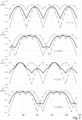
- the change in the effective chain radius ⁇ r (in millimeters) compared to the maximum value is plotted on the vertical axis.
- the two broken lines show the radius fluctuations of the individual link chains - e.g. dashed line for the first chain strand S1 and dashed line for the second chain strand S2 - and the solid line shows the curve averaged from this; this curve is "felt" by the load attached to the connecting part (e.g. connecting part B1).
- the compensation of the polygon effect results from the comparison between the amplitude of the radius fluctuation of an individual link chain and that of the averaged curve.
- the inventors go based on the Fig. 3 The results presented assume that, in general, a range of U 1 /2 ⁇ V ⁇ 2U 1 /3 is particularly favorable, whereby this range can be expanded on both sides by approximately U 1 /6 if less stringent requirements are imposed (thus U 1 /3 ⁇ V ⁇ 5U 1 /6). These areas are of course equal to the corresponding complementary areas, which result from applying the above complement formula (1) and/or replacing the values with negative values.
- the stop rocker carries out lurching compensating movements in the form of small rotations around the load direction b (this is, for example, in Fig. 2 can be seen from the small angle of the orientation of the stop rocker A1 relative to the axis of rotation d), which, however, is essential have less disruptive impact on the held load than the displacement due to the polygon effect.
- the sprockets R11, R12 can be manufactured separately, from suitable materials such as steel or plastic materials, for which manufacturing processes of a known type can be used, and then connected to one another, for example by welding or gluing.
- the two sprockets can also be assembled into a double sprocket by attaching them to a shaft (which can also be used to drive the chain drive).
- the sprockets can be secured by detachable connections, such as side pins, feather key grooves, splines or the like. be connected to each other in a rotationally fixed or rigid manner.
- the double chain wheel D1 can also be made in one piece.
- Fig. 4 shows more details of the sprockets of the chain drive Fig. 1 and 2 .
- the 4b and 4c each show a sectional view of the two sprockets along their center planes m1 and m2.
- Fig. 4d shows a longitudinal sectional view along a sectional plane through the axis of rotation d of the double chain wheel D1.
- Fig. 5 shows an example of a hoist arrangement I1, in which the double chain wheel D1 is rotatably mounted together with the shaft W1 belonging to it in a housing E1 mounted on a support plate.
- the housing E1 is mounted on the carrier plate P1, for example using screw bolts that fix the foot parts of the housing E1 to the carrier plate P1, or by other suitable fastening.
- the carrier plate P1 is provided with a rectangular window P0, for example, through which the two chains are guided in and out of the chain drive.
- the housing E1 surrounds the sprockets R11, R12 and on the inside limits the movement space of the link chains on the sprockets in the radial direction.
- the double chain wheel D1 is mounted concentrically in the housing E1 by the shaft W1 and its holders W11, W12, so that the wheel D1 can rotate in the housing E1 without touching it and at the same time is rotatably held therein.
- the brackets W11, W12 are in Fig. 5 merely indicated, they are attached to the support plate (not shown) and ensure stability Storage of the shaft W1 and thus the double chain wheel D1 in the hoist arrangement in a manner rotatable about the axis of rotation d .
- Fig. 6 shows a simplified representation of the hoist arrangement, namely only the chain drive together with the housing E1 (the foot parts of the housing are in Fig. 6 omitted for clarity).
- the 6b and 6c each show a sectional view along the central planes m1 and m2 of the two sprockets.
- Fig. 6d shows a longitudinal section view along a "horizontal" section plane 6-6 through the axis of rotation d of the double chain wheel D1.
- Fig. 6 shows a simplified representation of the hoist arrangement, namely only the chain drive together with the housing E1 (the foot parts of the housing are in Fig. 6 omitted for clarity).
- Fig. 6a a front view without inserted chain links.
- the 6b and 6c each show a sectional view along the central planes m1 and m2 of the two sprockets.
- Fig. 6d shows a longitudinal
- the housing has two grooves F1, F2 next to each other on the inside, in which standing links of the link chains running on the sprockets are guided.
- An inner part K1 also referred to as a scraper, closes off the chain drive on the output side and guides the chain sections as they enter the chain drive and in particular when the chains are removed (“stripped") from the chain wheels and leave the chain drive.
- the inner part K1 is held on the inner edges of the window P0 of the carrier plate P1, on which it is supported.
- Fig. 7-19 include various embodiments of the stop device that are not part of the invention. For the sake of clarity, only the chain drive is shown without a housing or lifting gear arrangement.
- the stop device can be equipped with a stop bracket on the connecting part side.
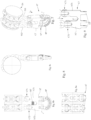
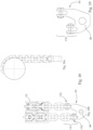
- Fig. 7 a perspective view of a chain drive system according to the second exemplary embodiment is shown, together with two chain strands S11, S12 of a chain hoist guided thereon, at the ends of which a stop device in the form of a stop component A1 is also attached.
- the Fig. 8 shows the chain drive system in three views ( Figs. 8a-8c ), namely in a supervision ( Fig. 8a ), a front view ( Fig. 8b ) and a side view ( Fig. 8c ; Viewing direction parallel to the axis of rotation d of the chain wheel and approximately parallel to the hinge axis x of the stop component A1).
- Fig. 9 shows the stop device Fig. 7 in a front view.
- the stop component A7 also referred to as the stop rocker A7, contains a body C7 and a stop bracket B7 that is articulated to it.
- the body C7 is designed with a U-shape that has two legs N71, N72, at the ends of which one of two connection points C71, C72 is provided.
- Each connection point C71, C72 is designed as a fork connection, in the space between which an end link of a chain strand is inserted and fastened with a bolt, which is secured, for example, with a split pin.
- the legs N71, N72 preferably have a small cross section, which enables elastic deformation of the body C7 and thereby allows cushioning and the resulting reduction in the rolling movement about the load direction b.
- the connecting web J7 between the legs can be designed with a small cross section in order to also allow elastic deformation (in particular torsion) in order to compensate for movement of the two chains transversely to the load direction.
- an intermediate element M7 can be arranged between the legs N71, N72, which serves as a damping and / or resilient element in order to additionally compensate for the movement of the two chains transversely to the load direction.
- the intermediate element preferably has a deformable material for damping vibrations between chains attached to the connection points.
- the intermediate element M7 can be designed, for example, as a block made of an elastomeric material and/or as a hydraulic damper element.
- Hinge parts O7 are provided on the side ("underside") of the body C7 facing away from the connection points C71, C72, which form a hinge-like joint with corresponding hinge parts of the bracket B7.
- the bracket B7 is thanks to the hinge joint X7 ( Fig. 8b ) can be pivoted about an axis x, which runs transversely to the load direction b and essentially in the plane in which the link chains run (thus essentially parallel to the axis of rotation d of the double chain wheel D1).
- the bracket B7 is attached to the body C7 using a hinge pin inserted along the axis x.
- the direction of the bolts of the connection points C71, C72 is preferably parallel to the orientation of the hinge axis x.
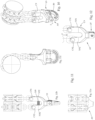
- FIG. 10 is a perspective view of a chain drive system according to this embodiment.
- the Fig. 11 shows the chain drive system in three views ( Figs. 11a-11c , analogous to Figs. 8a-8c ), namely in a supervision ( Fig. 11a ), a front view ( Fig. 11b ) and a side view ( Fig. 11c).
- Fig. 12 shows the stop rocker A9 Fig. 10 in a front view.
- the stop rocker A9 has a body C9 to which a stop bracket B9 is articulated;
- the stop bracket B9 is of the same design as the stop bracket B7, but is oriented differently with regard to the chain hoist of this exemplary embodiment.
- the body C9 is in turn designed with a U-shape with two legs N91, N92, at the ends of which one of two connection points C91, C92 is provided.
- Each connection point C91, C92 is designed as a fork connection, in the space between which an end link of a chain strand is inserted and fastened with a bolt, which is secured, for example, with a split pin.
- the legs N91, N92 preferably have a small cross section, which enables elastic deformation of the body C9 and thereby allows cushioning and the resulting reduction in rolling and compensating movements about the load direction b .
- the connection area J9 between the legs can be designed with a small cross section in order to also allow elastic deformation (in particular torsion) in order to compensate for movement of the two chains transversely to the load direction.
- an intermediate element M9 can be arranged between the legs N91, N92, which serves as a damping and / or resilient element in order to additionally compensate for the movement of the two chains transversely to the load direction.
- the intermediate element preferably has a deformable material for damping vibrations between chains attached to the connection points.
- the intermediate element M9 can be designed, for example, as a block made of an elastomeric material and/or as a hydraulic damper element.
- Hinge parts O9 are provided on the side ("underside") of the body C9 facing away from the connection points C91, C92, which form a hinge-like joint with corresponding hinge parts of the bracket B9.
- the bracket B9 is thanks to the hinge joint Y9 ( Fig. 11b ) can be pivoted about an axis x, which runs transversely to the load direction b and essentially transversely to the plane in which the link chains run (thus essentially perpendicular to the orientation of the axis of rotation d).
- the bracket B9 is attached to the body C9 using a hinge pin inserted along the axis y.
- the direction of the bolts of the connection points C91, C92 is preferably parallel to the orientation of the hinge axis y.
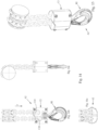
- FIG. 13 is a perspective view of a chain drive system according to this embodiment.
- the Fig. 14 shows the chain drive system in three views ( Figs. 14a-14c , analogous to Figs. 8a-8c ), namely in a supervision ( Fig. 14a ), a front view ( Fig. 14b ) and a side view ( Fig. 14c ).
- the stop component A2 is formed by a body C2, which is designed like a can and in the "upper" area of which connection points C21, C22 are provided. Using these connection points C21, C21, which are provided inside the body, respective end links of the chain strands are inserted and fastened with, for example, a bolt.
- the load hook B2 is mounted in the "underside" of the body of the stop component C2, preferably rotatable about an axis parallel to the load direction b . In a variant, however, the load hook B2 can be attached to the body C2 in a rotationally fixed manner.
- a double chain wheel in which the two chain wheels R11, R12 are joined together next to each other without any distance.
- the two sprockets may be spaced apart, as in Fig. 16a and 17a-e is shown as an example.
- two chain wheels R61, R62 are connected to one another in a rotationally fixed manner with a preselected angular offset V by a shaft W6 (with a smaller diameter than the chain wheels).
- Such a double chain wheel D6 with spaced chain wheels can easily be used in embodiments that correspond to the exemplary embodiments described above, in which case the distance between the two connection points in the stop devices must be increased accordingly, which can easily be adapted for the person skilled in the art.
- a chain deflection wheel can also be used, as shown in the following exemplary embodiment.
- a design of the chain drive component with chain wheels spaced apart from one another is particularly expedient.
- a chain hoist is shown in which the two chain strands S61, S62, which are guided on the double chain wheel D6, belong to the same link chain; this is guided via a chain deflection wheel Q6.
- Fig. 15 shows the chain drive system according to this embodiment
- Fig. 16 shows the chain drive system in three views ( Figs. 16a-16c , analogous to Figs. 8a-8c ), namely in a supervision ( Fig. 16a ), a front view ( Fig. 16b ) and a side view ( Fig. 16c ).
- Fig. 17 is the double chain wheel D6 in several views ( Fig. 17a-e ) shown, namely shows Fig.
- 17a a front view without inserted chain links
- 17b and 17c each a sectional view of one of the two chain wheels R61, R62 along the respective central plane m1 'or m2'
- Fig. 17d is a longitudinal sectional view along a section plane 7-7 along the rotation axis d' of the double sprocket D6
- Fig. 17e is a perspective view of the double sprocket D6.
- the link chain is guided with a first section, which corresponds to the first chain strand S61, over the first chain wheel R61 of the chain drive component designed as a double chain wheel D6, guided around the chain deflection wheel Q6 at the end of the load direction b and runs with a second section, which corresponds to the second chain strand S62, back over the second chain wheel R62 of the double chain wheel D6.
- the size of the distance between the two chain wheels R61 and R62 from one another (i.e. the length of the shaft W6, measured along the axis of rotation d ') can, for example, be conveniently selected so that the distance between the two center planes m1' and m2' from one another corresponds to the average swing diameter corresponds to the chain that is guided around the chain guide wheel Q6.
- the chain deflection wheel Q6 can have a central axle bore Y6 along its axis of rotation, or (not shown) can be designed with a shaft that preferably projects on both sides.
- the axis of rotation of the chain deflection wheel Q6 or the axle bore Y6 will lurch slightly as a result of the movement of the chain strands, but on average it is oriented essentially perpendicular to the orientation of the axis of rotation d' of the double chain wheel D6.
- a load can be attached to the axle of the double chain wheel D6, for example using a rod (not shown) or the like guided through the axle bore Y6.
- FIG. 18 shows the chain drive system according to this exemplary embodiment in a side view ( Fig. 18a ) and a front view ( Fig. 18b); Fig. 19 shows the stop component A8 in a front view.
- the stop component A8 (“stop rocker”) has a connection section C8 and a connecting part B8.
- the connection section C8 comprises two connection points C81, C82, each of which has a pair of opposite bores through which a bolt can be guided, in this exemplary embodiment each along a direction parallel to the axis of rotation d.
- the connecting part B8 contains an eye into the opening of which a hook can be hung or other slinging means to which the load is attached can be attached.
- a threaded hole (not shown) can also be provided, ie an opening with an internal thread.
Landscapes
- Engineering & Computer Science (AREA)
- Mechanical Engineering (AREA)
- General Engineering & Computer Science (AREA)
- Devices For Conveying Motion By Means Of Endless Flexible Members (AREA)
- Transmission Devices (AREA)
- Gears, Cams (AREA)
- Load-Engaging Elements For Cranes (AREA)
Priority Applications (1)
| Application Number | Priority Date | Filing Date | Title |
|---|---|---|---|
| EP23207336.1A EP4292973A3 (fr) | 2021-09-23 | 2021-09-23 | Transmission par chaîne à double roue dentée, dispositif de butée pour celle-ci, et système d'entraînement par chaîne |
Applications Claiming Priority (2)
| Application Number | Priority Date | Filing Date | Title |
|---|---|---|---|
| EP21198589.0A EP4155252B1 (fr) | 2021-09-23 | 2021-09-23 | Transmission par chaîne pourvue de roue à double chaîne, dispositif de butée associé, ainsi que système de transmission par chaîne |
| EP23207336.1A EP4292973A3 (fr) | 2021-09-23 | 2021-09-23 | Transmission par chaîne à double roue dentée, dispositif de butée pour celle-ci, et système d'entraînement par chaîne |
Related Parent Applications (1)
| Application Number | Title | Priority Date | Filing Date |
|---|---|---|---|
| EP21198589.0A Division EP4155252B1 (fr) | 2021-09-23 | 2021-09-23 | Transmission par chaîne pourvue de roue à double chaîne, dispositif de butée associé, ainsi que système de transmission par chaîne |
Publications (2)
| Publication Number | Publication Date |
|---|---|
| EP4292973A2 true EP4292973A2 (fr) | 2023-12-20 |
| EP4292973A3 EP4292973A3 (fr) | 2024-03-13 |
Family
ID=77913003
Family Applications (2)
| Application Number | Title | Priority Date | Filing Date |
|---|---|---|---|
| EP23207336.1A Withdrawn EP4292973A3 (fr) | 2021-09-23 | 2021-09-23 | Transmission par chaîne à double roue dentée, dispositif de butée pour celle-ci, et système d'entraînement par chaîne |
| EP21198589.0A Active EP4155252B1 (fr) | 2021-09-23 | 2021-09-23 | Transmission par chaîne pourvue de roue à double chaîne, dispositif de butée associé, ainsi que système de transmission par chaîne |
Family Applications After (1)
| Application Number | Title | Priority Date | Filing Date |
|---|---|---|---|
| EP21198589.0A Active EP4155252B1 (fr) | 2021-09-23 | 2021-09-23 | Transmission par chaîne pourvue de roue à double chaîne, dispositif de butée associé, ainsi que système de transmission par chaîne |
Country Status (4)
| Country | Link |
|---|---|
| US (1) | US12515929B2 (fr) |
| EP (2) | EP4292973A3 (fr) |
| JP (1) | JP2023046385A (fr) |
| CN (1) | CN115853981A (fr) |
Families Citing this family (1)
| Publication number | Priority date | Publication date | Assignee | Title |
|---|---|---|---|---|
| EP4553032B1 (fr) * | 2023-11-07 | 2025-10-08 | Pewag Austria GmbH | Dispositif d'entraînement à chaîne et élévateur à pignon à chaîne double |
Family Cites Families (13)
| Publication number | Priority date | Publication date | Assignee | Title |
|---|---|---|---|---|
| GB716999A (en) * | 1952-03-28 | 1954-10-20 | Maby & Co | Improvements in chain hoists |
| DE1232718B (de) * | 1962-07-31 | 1967-01-19 | Demag Zug Gmbh | Kettenfuehrung fuer Rundgliederketten an Kettenflaschenzuegen |
| US3596879A (en) * | 1968-10-22 | 1971-08-03 | Aluminum Products Inc | Chain hoist |
| DE4104985A1 (de) * | 1991-02-19 | 1992-08-20 | Stahl R Foerdertech Gmbh | Schwingarmer elektrokettenzug |
| DE4111520A1 (de) * | 1991-02-19 | 1992-10-29 | Stahl R Foerdertech Gmbh | Schwingarmer elektrokettenzug |
| DE4201974C2 (de) * | 1992-01-22 | 1994-07-21 | Rud Ketten Rieger & Dietz | Hebezeug |
| DE19817013C2 (de) * | 1998-04-17 | 2000-08-31 | Stahl R Foerdertech Gmbh | Kettenzug |
| FI106304B (fi) * | 1999-03-26 | 2001-01-15 | Kci Kone Cranes Int Oy | Ketjunostin |
| DE202007002119U1 (de) * | 2007-02-08 | 2008-06-26 | Bucyrus Dbt Europe Gmbh | Kettenrad für Kettenantriebe |
| CN101961780A (zh) * | 2010-09-21 | 2011-02-02 | 南通宏德机电有限公司 | 一种电动翻箱装置 |
| CN104418234A (zh) * | 2013-08-29 | 2015-03-18 | 高则行 | 起重装置以及包括该起重装置的手拉葫芦 |
| CN109052137B (zh) * | 2018-09-12 | 2020-08-11 | 中车大连机车车辆有限公司 | 一种可调式机车前窗玻璃安装吊具 |
| EP4427865A1 (fr) * | 2023-03-09 | 2024-09-11 | Pewag Engineering GmbH | Procédé et dispositif de soudage en chaîne |
-
2021
- 2021-09-23 EP EP23207336.1A patent/EP4292973A3/fr not_active Withdrawn
- 2021-09-23 EP EP21198589.0A patent/EP4155252B1/fr active Active
-
2022
- 2022-08-29 JP JP2022136232A patent/JP2023046385A/ja active Pending
- 2022-09-01 US US17/901,047 patent/US12515929B2/en active Active
- 2022-09-23 CN CN202211163829.4A patent/CN115853981A/zh active Pending
Also Published As
| Publication number | Publication date |
|---|---|
| EP4292973A3 (fr) | 2024-03-13 |
| EP4155252A1 (fr) | 2023-03-29 |
| EP4155252C0 (fr) | 2023-11-29 |
| CN115853981A (zh) | 2023-03-28 |
| EP4155252B1 (fr) | 2023-11-29 |
| US20230091350A1 (en) | 2023-03-23 |
| US12515929B2 (en) | 2026-01-06 |
| JP2023046385A (ja) | 2023-04-04 |
Similar Documents
| Publication | Publication Date | Title |
|---|---|---|
| EP2047141B1 (fr) | Pignon à chaîne, à force portante élevée | |
| DE102010048934B4 (de) | Gliederkette | |
| EP3461782A1 (fr) | Dispositif de levage destiné à lever et à abaisser des objets lourds | |
| EP4155252B1 (fr) | Transmission par chaîne pourvue de roue à double chaîne, dispositif de butée associé, ainsi que système de transmission par chaîne | |
| EP1440253B1 (fr) | Chaine, notamment chaine d'un engin de levage | |
| DE2621249C3 (de) | Tragbares, hydraulisch betätigtes Unfall-Rettungsgerät mit Spreizschnabel | |
| DE602005001846T2 (de) | Zum stützen und führen von kleidung in hängefördersystemen verwendetes band mit öffnungen | |
| EP2912343B1 (fr) | Chaîne articulée et mécanisme d'entraînement d'une chaîne articulée, en particulier pour une construction hydraulique en acier et un élévateur à godets sur chaîne | |
| WO2008014836A2 (fr) | Poulie de renvoi avec meilleure utilisation de la chaîne | |
| DE102016111542B4 (de) | Schubkette mit standardisiertem Endstück | |
| DE2248006A1 (de) | Blattfederkonstruktion | |
| EP0367755B1 (fr) | Dispositif d'entraînement | |
| EP3300513B1 (fr) | Transmission à chaîne comprenant un rail combiné | |
| DE102004021708B4 (de) | Vereinfachte Katze mit niedriger Bauhöhe | |
| DE102017113079A1 (de) | Hubvorrichtung mit rückensteifer Kette | |
| EP3330110A1 (fr) | Support de palier permettant de fixer un bras oscillant longitudinal à essieux rigides pourvu de composant d'appui influençant le cas de charge de fonctionnement | |
| WO2007121957A1 (fr) | Chaîne transporteuse | |
| DE3502946C2 (de) | Kettenförderer | |
| WO2020074370A1 (fr) | Ligne de convoyage pour un convoyeur | |
| EP4553032B1 (fr) | Dispositif d'entraînement à chaîne et élévateur à pignon à chaîne double | |
| DE29915220U1 (de) | Bauteil mit Federelementen | |
| EP0193489A2 (fr) | Transporteur à chaîne | |
| WO2020074372A1 (fr) | Maillon de chaîne d'une chaîne articulée pour un convoyeur | |
| DE102018116691A1 (de) | Kettentrieb mit durchhangfreiem Leertrum | |
| CH662757A5 (en) | Sprocket (pintle) chain with variable double pitch |
Legal Events
| Date | Code | Title | Description |
|---|---|---|---|
| PUAI | Public reference made under article 153(3) epc to a published international application that has entered the european phase |
Free format text: ORIGINAL CODE: 0009012 |
|
| STAA | Information on the status of an ep patent application or granted ep patent |
Free format text: STATUS: THE APPLICATION HAS BEEN PUBLISHED |
|
| AC | Divisional application: reference to earlier application |
Ref document number: 4155252 Country of ref document: EP Kind code of ref document: P |
|
| AK | Designated contracting states |
Kind code of ref document: A2 Designated state(s): AL AT BE BG CH CY CZ DE DK EE ES FI FR GB GR HR HU IE IS IT LI LT LU LV MC MK MT NL NO PL PT RO RS SE SI SK SM TR |
|
| PUAL | Search report despatched |
Free format text: ORIGINAL CODE: 0009013 |
|
| AK | Designated contracting states |
Kind code of ref document: A3 Designated state(s): AL AT BE BG CH CY CZ DE DK EE ES FI FR GB GR HR HU IE IS IT LI LT LU LV MC MK MT NL NO PL PT RO RS SE SI SK SM TR |
|
| RIC1 | Information provided on ipc code assigned before grant |
Ipc: B66D 3/26 20060101AFI20240206BHEP |
|
| STAA | Information on the status of an ep patent application or granted ep patent |
Free format text: STATUS: THE APPLICATION IS DEEMED TO BE WITHDRAWN |
|
| 18D | Application deemed to be withdrawn |
Effective date: 20240914 |