EP4293151A1 - Machine à laver et à sécher - Google Patents
Machine à laver et à sécher Download PDFInfo
- Publication number
- EP4293151A1 EP4293151A1 EP21925725.0A EP21925725A EP4293151A1 EP 4293151 A1 EP4293151 A1 EP 4293151A1 EP 21925725 A EP21925725 A EP 21925725A EP 4293151 A1 EP4293151 A1 EP 4293151A1
- Authority
- EP
- European Patent Office
- Prior art keywords
- air duct
- washing
- drying machine
- filter
- water
- Prior art date
- Legal status (The legal status is an assumption and is not a legal conclusion. Google has not performed a legal analysis and makes no representation as to the accuracy of the status listed.)
- Withdrawn
Links
Images





Classifications
-
- D—TEXTILES; PAPER
- D06—TREATMENT OF TEXTILES OR THE LIKE; LAUNDERING; FLEXIBLE MATERIALS NOT OTHERWISE PROVIDED FOR
- D06F—LAUNDERING, DRYING, IRONING, PRESSING OR FOLDING TEXTILE ARTICLES
- D06F58/00—Domestic laundry dryers
- D06F58/20—General details of domestic laundry dryers
- D06F58/22—Lint collecting arrangements
-
- D—TEXTILES; PAPER
- D06—TREATMENT OF TEXTILES OR THE LIKE; LAUNDERING; FLEXIBLE MATERIALS NOT OTHERWISE PROVIDED FOR
- D06F—LAUNDERING, DRYING, IRONING, PRESSING OR FOLDING TEXTILE ARTICLES
- D06F25/00—Washing machines with receptacles, e.g. perforated, having a rotary movement, e.g. oscillatory movement, the receptacle serving both for washing and for centrifugally separating water from the laundry and having further drying means, e.g. using hot air
-
- D—TEXTILES; PAPER
- D06—TREATMENT OF TEXTILES OR THE LIKE; LAUNDERING; FLEXIBLE MATERIALS NOT OTHERWISE PROVIDED FOR
- D06F—LAUNDERING, DRYING, IRONING, PRESSING OR FOLDING TEXTILE ARTICLES
- D06F2103/00—Parameters monitored or detected for the control of domestic laundry washing machines, washer-dryers or laundry dryers
- D06F2103/68—Operation mode; Program phase
-
- D—TEXTILES; PAPER
- D06—TREATMENT OF TEXTILES OR THE LIKE; LAUNDERING; FLEXIBLE MATERIALS NOT OTHERWISE PROVIDED FOR
- D06F—LAUNDERING, DRYING, IRONING, PRESSING OR FOLDING TEXTILE ARTICLES
- D06F2105/00—Systems or parameters controlled or affected by the control systems of washing machines, washer-dryers or laundry dryers
- D06F2105/46—Drum speed; Actuation of motors, e.g. starting or interrupting
-
- D—TEXTILES; PAPER
- D06—TREATMENT OF TEXTILES OR THE LIKE; LAUNDERING; FLEXIBLE MATERIALS NOT OTHERWISE PROVIDED FOR
- D06F—LAUNDERING, DRYING, IRONING, PRESSING OR FOLDING TEXTILE ARTICLES
- D06F33/00—Control of operations performed in washing machines or washer-dryers
- D06F33/50—Control of washer-dryers characterised by the purpose or target of the control
- D06F33/52—Control of the operational steps, e.g. optimisation or improvement of operational steps depending on the condition of the laundry
-
- Y—GENERAL TAGGING OF NEW TECHNOLOGICAL DEVELOPMENTS; GENERAL TAGGING OF CROSS-SECTIONAL TECHNOLOGIES SPANNING OVER SEVERAL SECTIONS OF THE IPC; TECHNICAL SUBJECTS COVERED BY FORMER USPC CROSS-REFERENCE ART COLLECTIONS [XRACs] AND DIGESTS
- Y02—TECHNOLOGIES OR APPLICATIONS FOR MITIGATION OR ADAPTATION AGAINST CLIMATE CHANGE
- Y02B—CLIMATE CHANGE MITIGATION TECHNOLOGIES RELATED TO BUILDINGS, e.g. HOUSING, HOUSE APPLIANCES OR RELATED END-USER APPLICATIONS
- Y02B40/00—Technologies aiming at improving the efficiency of home appliances, e.g. induction cooking or efficient technologies for refrigerators, freezers or dish washers
Definitions
- the present invention relates to a washing and drying machine that cleans an air duct filter disposed on the upstream side of an air blower.
- Patent Literature 1 describes "A drying and washing machine that includes a water tank, a rotational drum that is rotatably disposed in the water tank, a dehumidification section that dehumidifies air led from the interior of the rotational drum, a heating section that heats the air dehumidified by the dehumidification section, an air blowing section that leads the air in the interior of the rotational drum to the dehumidification section and blows the air heated by the heating section into the interior of the rotational drum, and filter means that is provided in a path on a suction port side between the rotational drum and the air blowing section and on the upstream side of air flow generated by the air blowing section during a drying step and is disposed so as to be immersed in washing water supplied into the water tank during a washing step or a
- a filter is disposed in the lower portion of the back face of the water tank immersed in the washing water during the washing step or during the rinsing step, so that a foreign substance such as cotton dust and thread waste (hereinafter, referred to as a "lint") that is contained in circulation air during the drying step and is larger than the coarseness of the mesh of the filter (in paragraph 0060 of the literature, 1 mm to 3 mm) is collected, so that the foreign substance is prevented from intruding into the air blower and the heater in the downstream of the filter.
- a foreign substance such as cotton dust and thread waste
- the lint that adheres to the front side of the filter during the drying step is removed from the front side of the filter by the water flow when the rotational drum is rotated during the washing step or the rinsing step thereafter, and is then drained from the drainage port opening to the lowermost portion of the water tank, so that the clogging on the front side of the filter can be eliminated to prevent the air amount of the circulation air during the drying step from being reduced.
- most of the lint contained in the circulation air during the drying step is approximately several tens to several hundreds of ⁇ m smaller than the mesh of the filter, so that most of the lint in the circulation air passes through the filter, and intrudes into the air duct provided from the filter to the air blower.
- the fine lint that intrudes into the air duct absorbs cooling water supplied into the air duct for dehumidification during the drying step or water supplied to the water tank during the washing step or during the rinsing step, and combines with the lint therearound to become a lint clump which is then accumulated on the back side of the filter.
- the lint clump that is accumulated on the back side of the filter and is larger than the mesh does not flow reversely to the front side of the filter in the cleaning of Patent Literature 1, so that when the drying step is repeated, the lint adherence to the back side of the filter increases gradually, and the clogging on the back side of the filter progresses gradually.
- an object of the present invention is to provide a washing and drying machine capable of preventing the clogging of an air duct filter by draining a lint clump generated in an air duct provided from the back side of the air duct filter to an air blower.
- a washing and drying machine of this example includes an inner tank that accommodates laundry and rotates during each of a washing step, a rinsing step, and a water removal step, an outer tank that surrounds the inner tank and stores water, a drainage channel that drains the water in the outer tank, an air blower that supplies air to the inner tank and the outer tank, an air duct that connects the outer tank with the air blower, an air duct filter that is provided between the outer tank and the air duct and collects lint traveling toward a suction port of the air duct, and a lint drainage channel that connects the air duct with the drainage channel.
- the clogging of the air duct filter is prevented by draining the lint clump generated in the air duct provided from the back side of the air duct filter to the air blower, so that it is possible to prevent lack of drying in clothes and the like and drainage failure in the air duct.
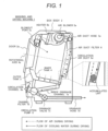
- washing and drying machine 1 of the comparative example Before describing the washing and drying machine of the present invention, the washing and drying machine 1 of the comparative example will be first described with reference to Figures 1 and 2 . Note that in the washing and drying machine of Patent Literature 1, the air blower and the heater are disposed below the drum rotational axis, but in the washing and drying machine 1 of the comparative. example, the air blower and the heater are disposed above the drum rotational axis.
- the washing and drying machine 1 of the comparative example includes a box body 2, a door 2a, an outer tank 3, an inner tank 4, an air blowing device 5 (an air blower 5a, a heater 5b, a blowout port 5c, a circulation air duct 5d, an air duct hose 5e), an air duct filter 6, a drainage channel 7 (an inside drainage channel 7a, a channel filter 7b, a drainage valve 7c, a drainage hose 7d), a circulation pump 8, and a circulation channel 8a.
- an air blowing device 5 an air blower 5a, a heater 5b, a blowout port 5c, a circulation air duct 5d, an air duct hose 5e
- an air duct filter 6 a drainage channel 7 (an inside drainage channel 7a, a channel filter 7b, a drainage valve 7c, a drainage hose 7d), a circulation pump 8, and a circulation channel 8a.
- the box body 2 is the outer casing of the washing and drying machine 1, and the door 2a that is openable and closeable is mounted to the opening of the front face of the box body 2.
- the outer tank 3 is disposed in the interior of the box body 2, and can store water in its interior.
- the inner tank 4 is disposed in the interior of the outer tank 3, and rotates around a rotational axis 4a at low speed or high speed in a state of accommodating laundry such as clothes during each of a washing step, a rinsing step, a water removal step, and a drying step.
- the air blowing device 5 generates circulation air indicated by dashed line arrows in the drawing during the drying step, and dries the laundry.
- the air blowen out from the air blower 5a is heated by the heater 5b in the downstream, and then passes through the blowout port 5c to be supplied to the inner tank 4.
- the air supplied to the inner tank 4 heats the wet laundry accommodated in the inner tank 4 to take away moisture, and then passes through the outer peripheral hole of the inner tank 4 to flow out into the space of the gap between the inner tank 4 and the outer tank 3, thereby further passing through the air duct filter 6 that is a mesh filter, to reach the circulation air duct 5d.
- the air that flows into the circulation air duct 5d has humidity increased by taking away the moisture from the laundry, so that cooling water indicated by solid line arrows in the drawing is supplied from the upper portion of the circulation air duct 5d, the air at high humidity is cooled to cause water vapor condensation, and the air is dehumidified. Then, the dried air after the dehumidification passes through the air duct hose 5e to return to the air blower 5a. In this way, the air blowing device 5 supplies the high temperature drying air to the wet laundry in the inner tank 4, thereby promoting the drying of the laundry.
- the drainage channel 7 is a path for draining the water from the outer tank 3, and includes the inside drainage channel 7a that communicates with the opening of the bottom face of the outer tank 3, the channel filter 7b that collects the lint in the drainage water flowing through the inside drainage channel 7a, the drainage valve 7c that is closed mainly during the washing step and during the rinsing step and is opened during other steps, and the drainage hose 7d through which the drainage water passes when the drainage valve 7c is opened. Note that the lint collected by the channel filter 7b is cleaned by a user, as needed.
- the circulation pump 8 is provided on the downstream side of the channel filter 7b, and circulates the drainage water in the outer tank 3 through the circulation channel 8a during the washing step and during the rinsing step.
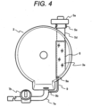
- Figure 2 is a front view of the outer tank 3 and the air duct filter 6 when the inner tank 4 is not illustrated.
- the circulation air duct 5d provided from the outer tank 3 to the air blower 5a is disposed below the air blower 5a and on the back side of the outer tank 3 so as to connect both of the outer tank 3 and the air blower 5a in the shortest distance.
- a suction port 3a that is vertically long and large is provided in the back face of the outer tank 3, and the suction port 3a is covered by the air duct filter 6 having a large area.
- a mechanical force by the laundry in the inner tank 4 rubbing against each other during the washing step and during the rinsing step and a mechanical force and the like by the air supplied to the inner tank 4 during the drying step separate the fiber of the laundry to generate the lint.
- the generated lint which is heavy in wet state in the early stage of the drying step, does not drift, but becomes light and starts drifting as the drying progresses.
- the lint larger than the mesh of the air duct filter 6 is collected by the air duct filter 6, and is drained to the inside drainage channel 7a after the completion of the washing step and the rinsing step thereafter.
- Example 1 of the present invention a washing and drying machine 1A according to Example 1 of the present invention will be described with reference to Figures 3 to 6B . Note that the overlapped description of the common points with the washing and drying machine 1 of the comparative example is omitted.
- a lint drainage channel 9 that connects the lower portion of the circulation air duct 5d with the inside drainage channel 7a is added to the configuration of the washing and drying machine 1 of the comparative example.
- the lint having a size of approximately several tens of ⁇ m passes through the air duct filter 6 to intrude into the circulation air duct 5d during the drying step.
- the lint clump is generated by the same action as explained in the comparative example, but since the lint clump in the early stage of the generation is sufficiently small, the lint clump passes through the lint drainage channel 9 to be drained into the inside drainage channel 7a with the cooling water during the drying step and with the drainage water from the outer tank 3 during the drainage after the completion of the washing step and the rinsing step.
- a lint drainage channel air duct side connection section 9a is desirably at a position lower than the highest height that the water flow stirred by the high speed rotation of the inner tank 4 reaches, from ⁇ The cleaning method of the air duct filter 6> described later.
- the diameter of the lint drainage channel 9 may be approximately several mm, but the lint drainage channel 9 is desirably designed to a diameter of approximately 6 to 10 mm so that even the lint clump that grows to some degree can be drained.
- a lint drainage channel drainage channel side connection section 9b provided at the lower end of the lint drainage channel 9 is desirably connected to the upstream side of the channel filter 7b so that the lint drained through the lint drainage channel 9 can be collected by the channel filter 7b, but the lint drainage channel drainage channel side connection section 9b may be connected to the downstream side of the channel filter 7b to directly flow the lint clump to a sewer and the like.
- the operation of the washing and drying machine 1A is started by the control of a controller that controls water injection, drainage, the rotation of the inner tank 4, the driving of the air blower 5a, the heating of the heater 5b, and the supply of cooling water, and the like.
- step S1 the controller executes a washing step by storing water in a predetermined amount in the outer tank 3 in a state of closing the drainage valve 7c and then rotating the inner tank 4 at low speed.
- step S2 the controller executes a first water removal step by rotating the inner tank 4 at high speed in a state of opening the drainage valve 7c.
- step S3 the controller executes a first rinsing step by storing water in a predetermined amount in the outer tank 3 in a state of closing the drainage valve 7c and then rotating the inner tank 4 at low speed.
- step S4 the controller executes a second water removal step by rotating the inner tank 4 at high sped in a state of opening the drainage valve 7c.
- step S5 the controller executes a final rinsing step by storing water in a predetermined amount in the outer tank 3 in a state of closing the drainage valve 7c and then rotating the inner tank 4 at low speed.
- step S6 the controller executes a final water removal step by rotating the inner tank 4 at high speed in a state of opening the drainage valve 7c.
- step S7 the controller determines whether the execution of the drying step has been set. Then, when the drying step has been set, the process goes to step S8, and when the drying step has not been set, the operation is ended.
- step S8 the controller drives the air blowing device 5 in a state of opening the drainage valve 7c, and dries the laundry in the inner tank 4. Then, when the drying of the laundry ends, the operation is ended.
- the cleaning method of the air duct filter 6 in the washing and drying machine 1A of this example will be described.
- the cleaning of the air duct filter 6 may be executed by any one of steps S1 to S6, but from the viewpoint of preventing the lint adherence to the laundry, the cleaning of the air duct filter 6 is desirably performed between the final rinsing and the final water removal, so that in this example, the cleaning of the air duct filter 6 is executed in step S5 that is the final rinsing step.
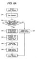
- FIG. 6A is an example of step S5 that is the final rinsing step.
- the controller determines whether the drying step has been executed during a previous operation (that is, whether the fine lint has been sucked into the circulation air duct 5d) (step S52), and when the drying step has been executed, the controller starts the cleaning step of the air duct filter 6. On the other hand, when the drying step has not been executed, the controller ends the final rinsing step of step S5 without cleaning the air duct filter 6, and executes the next final water removal step (step S6).
- the controller first opens the drainage valve 7c, drains the remaining water used in the rinsing to the constant water level (step S53), closes the drainage valve 7c, and rotates the inner tank 4 at the number of rotations higher than the number of rotations during the rinsing step (step S54).
- step S55 since the water in the outer tank 3 is rolled up to the upper end of the air duct filter 6 by the inner tank 4 that rotates at high speed, the lint on the entire faces on both sides of the air duct filter 6 can be washed away by the stirred water flow (step S55).
- the controller opens the drainage valve 7c in a state of maintaining the high speed rotation of the inner tank 4, and completely drains the remaining water in the outer tank 3 while continuing the cleaning of the air duct filter 6 (step S56).
- the lint on the front side of the air duct filter 6 is directly drained to the inside drainage channel 7a.
- the lint on the bask side of the air duct filter 6 is drained to the inside drainage channel 7a through the lint drainage channel 9.
- the upper end of the air duct filter 6 is designed so as to be lower than the highest height that the water flow stirred by the high speed rotation of the inner tank 4 reaches in step S55. This is because if the upper end of the air duct filter 6 is higher than the height of the rolled-up water flow, the periphery of the upper end of the air duct filter 6 cannot be cleaned and the clogging in the periphery of the upper end cannot be eliminated.
- FIG. 6B is another example of step S5 that is the final rinsing step.
- the controller opens the drainage valve 7c, and completely drains the remaining water in the outer tank 3 (step S51a). Thereafter, the controller determines whether the drying step has been executed during a previous operation (that is, whether the fine lint has been sucked into the circulation air duct 5d) (step S52), and when the drying step has been executed, the controller starts the cleaning step of the air duct filter 6. On the other hand, when the drying step has not been executed, the controller ends the final rinsing step of step S5 without cleaning the air duct filter 6, and executes the next final water removal step (step S6). .
- the controller first rotates the inner tank 4 at the number of rotations higher than the number of rotations during the rinsing step (step S54a), then closes the drainage valve 7c, and supplies water into the outer tank 3 to the constant water level (step S53a). At this time, since the water in the outer tank 3 is rolled up to the upper end of the air duct filter 6 by the inner tank 4 that rotates at high speed, the lint on the entire faces on both sides of the air duct filter 6 can be washed away by the stirred water flow (step S55).
- the controller opens the drainage valve 7c in a state of maintaining the high speed rotation of the inner tank 4, and completely drains the remaining water in the outer tank 3 while continuing the cleaning of the air duct filter 6 (step S56).
- the lint on the front side of the air duct filter 6 is directly drained to the inside drainage channel 7a, and the lint on the bask side of the air duct filter 6 is drained to the inside drainage channel 7a through the lint drainage channel 9.
- step S55 cleaning the air duct filter 6 in step S55 by the final rinsing of the rinsing step has been described, but the cleaning step of step S55 may be provided between the rinsing step and the water removal step or at the start of the water removal step.
- the lint can be drained to the outside of the outer tank 3 in a state where the lint torn off from the air duct filter 6 is prevented from adhering to the clothes in the inner tank.
- the cleaning step of the air duct filter 6 may be executed as part of the intra-tank cleaning step of cleaning the inner wall of the outer tank 3 arbitrarily set by the user without determining whether or not the drying step has been executed during the previous operation.
- the clogging of the air duct filter is prevented by draining the lint clump generated in the air duct provided from the back side of the air duct filter to the air blower, so that it is possible to prevent lack of drying in laundry and drainage failure in the air duct.
- Example 2 a washing and drying machine 1B according to Example 2 of the present invention will be described with reference to Figures 7 to 8B . Note that the overlapped description of the common points with Example 1 is omitted.
- a sub-air duct filter 6a in front of the suction port of the air blower 5a is added to the configuration of the washing and drying machine 1A of Example 1.
- the lint clumps of the front and back of the air duct filter 6 can be cleaned and removed, but the fine lint that passes through the air duct filter 6 may drift in the circulation air to be sucked into the air blower 5a or further, to be accumulated on the heater 5b.
- the air blower 5a and the heater 5b are designed so that their performance is not lowered by the fine lint, but, for example, when the lint clumps in a large amount that grow at positions where the ventilation resistance is large, like the bellows portion of the air duct hose 5e, are sucked into the air blower 5a or are accumulated on the heater 5b, their performance may be deteriorated with time.
- the lint clump that moves by drifting in the circulation air after the lint clump grows, for example, in the vicinity of the air duct hose 5e is collected by the sub-air duct filter 6a disposed just before the air blower 5a, so that the lint clump can be prevented from being sucked into the air blower 5a or accumulated on the heater 5b.
- Figure 8A is an example of a configuration for cleaning the sub-air duct filter 6a, and a water supply port 10 that supplies cooling water to the front face (upstream side) of the sub-air duct filter 6a is provided.
- the cooling water supplied from the water supply port 10 washes away the front face of the sub-air duct filter 6a, and then falls into the circulation air duct 5d, so that even when the coarseness of the mesh of the sub-air duct filter 6a is small, the lint clump can be removed from the front face of the sub-air duct filter 6a.
- Figure 8B is another example of a configuration for cleaning the sub-air duct filter 6a, and the water supply port 10 that supplies cooling water to the back face (downstream side) of the sub-air duct filter 6a is provided.
- the cooling water supplied from the water supply port 10 flows out from the back face of the sub-air duct filter 6a to the front face of the sub-air duct filter 6a, and then falls into the circulation air duct 5d, so that the clogging of the sub-air duct filter 6a can be efficiently removed.
Landscapes
- Engineering & Computer Science (AREA)
- Textile Engineering (AREA)
- Detail Structures Of Washing Machines And Dryers (AREA)
- Control Of Washing Machine And Dryer (AREA)
- Main Body Construction Of Washing Machines And Laundry Dryers (AREA)
Applications Claiming Priority (2)
| Application Number | Priority Date | Filing Date | Title |
|---|---|---|---|
| JP2021020817A JP7551528B2 (ja) | 2021-02-12 | 2021-02-12 | ドラム式洗濯乾燥機 |
| PCT/JP2021/015164 WO2022172476A1 (fr) | 2021-02-12 | 2021-04-12 | Machine à laver et à sécher |
Publications (2)
| Publication Number | Publication Date |
|---|---|
| EP4293151A1 true EP4293151A1 (fr) | 2023-12-20 |
| EP4293151A4 EP4293151A4 (fr) | 2024-12-18 |
Family
ID=82837646
Family Applications (1)
| Application Number | Title | Priority Date | Filing Date |
|---|---|---|---|
| EP21925725.0A Withdrawn EP4293151A4 (fr) | 2021-02-12 | 2021-04-12 | Machine à laver et à sécher |
Country Status (4)
| Country | Link |
|---|---|
| EP (1) | EP4293151A4 (fr) |
| JP (3) | JP7551528B2 (fr) |
| CN (1) | CN116635582A (fr) |
| WO (1) | WO2022172476A1 (fr) |
Families Citing this family (1)
| Publication number | Priority date | Publication date | Assignee | Title |
|---|---|---|---|---|
| JP7551528B2 (ja) * | 2021-02-12 | 2024-09-17 | 日立グローバルライフソリューションズ株式会社 | ドラム式洗濯乾燥機 |
Family Cites Families (11)
| Publication number | Priority date | Publication date | Assignee | Title |
|---|---|---|---|---|
| IT1284443B1 (it) * | 1996-06-26 | 1998-05-21 | Candy Spa | Macchina lavatrice di tipo domestico con circuito chiuso di asciugatura, condensazione ad aria del vapore e filtro autopulente |
| JP3807099B2 (ja) * | 1998-06-10 | 2006-08-09 | 松下電器産業株式会社 | ドラム式洗濯乾燥機 |
| JP3863167B1 (ja) | 2005-08-05 | 2006-12-27 | シャープ株式会社 | 乾燥洗濯機 |
| JP2008212372A (ja) | 2007-03-02 | 2008-09-18 | Kowa Co Ltd | 洗濯乾燥機 |
| EP2607546A4 (fr) | 2010-08-19 | 2016-03-23 | Lg Electronics Inc | Machine à laver ayant une fonction de séchage, et procédé pour sa commande |
| JP2013085687A (ja) | 2011-10-18 | 2013-05-13 | Panasonic Corp | 衣類乾燥機 |
| JP5897390B2 (ja) | 2012-04-24 | 2016-03-30 | 株式会社東芝 | 洗濯乾燥機 |
| JP2014083392A (ja) | 2012-10-26 | 2014-05-12 | Sharp Corp | 洗濯機 |
| WO2016108101A1 (fr) * | 2014-12-30 | 2016-07-07 | Indesit Company S.P.A. | Machine à laver/sécher avec un dispositif pour nettoyer un filtre à air |
| KR102515954B1 (ko) * | 2016-01-05 | 2023-03-30 | 엘지전자 주식회사 | 세탁물처리장치 및 그의 청소노즐제어방법 |
| JP7551528B2 (ja) * | 2021-02-12 | 2024-09-17 | 日立グローバルライフソリューションズ株式会社 | ドラム式洗濯乾燥機 |
-
2021
- 2021-02-12 JP JP2021020817A patent/JP7551528B2/ja active Active
- 2021-04-12 CN CN202180078965.0A patent/CN116635582A/zh active Pending
- 2021-04-12 WO PCT/JP2021/015164 patent/WO2022172476A1/fr not_active Ceased
- 2021-04-12 EP EP21925725.0A patent/EP4293151A4/fr not_active Withdrawn
-
2022
- 2022-10-07 JP JP2022162312A patent/JP7426458B2/ja active Active
-
2024
- 2024-01-22 JP JP2024007276A patent/JP7478915B2/ja active Active
Also Published As
| Publication number | Publication date |
|---|---|
| WO2022172476A1 (fr) | 2022-08-18 |
| JP2022123481A (ja) | 2022-08-24 |
| JP2024026890A (ja) | 2024-02-28 |
| CN116635582A (zh) | 2023-08-22 |
| JP7551528B2 (ja) | 2024-09-17 |
| EP4293151A4 (fr) | 2024-12-18 |
| JP2022174349A (ja) | 2022-11-22 |
| JP7478915B2 (ja) | 2024-05-07 |
| JP7426458B2 (ja) | 2024-02-01 |
Similar Documents
| Publication | Publication Date | Title |
|---|---|---|
| JP2013085687A (ja) | 衣類乾燥機 | |
| JP2008006045A (ja) | 洗濯乾燥機 | |
| JP3898687B2 (ja) | ドラム式洗濯乾燥機 | |
| JP6295424B2 (ja) | 洗濯乾燥機 | |
| JP3863167B1 (ja) | 乾燥洗濯機 | |
| EP4293151A1 (fr) | Machine à laver et à sécher | |
| JP6373020B2 (ja) | 乾燥機 | |
| JP4400404B2 (ja) | 洗濯乾燥機 | |
| JP2013085684A (ja) | 衣類乾燥機 | |
| TWI660095B (zh) | 洗衣乾衣機 | |
| JP3812528B2 (ja) | ドラム式洗濯乾燥機 | |
| JP3898675B2 (ja) | ドラム式洗濯乾燥機 | |
| KR102662308B1 (ko) | 의류처리장치 및 그의 제어방법 | |
| JP2001269495A (ja) | ドラム式洗濯機 | |
| JP3939731B2 (ja) | ドラム式乾燥洗濯機 | |
| CN117431742A (zh) | 衣类处理装置 | |
| JP3970294B2 (ja) | ドラム式乾燥洗濯機 | |
| WO2023203833A1 (fr) | Machine à laver et à sécher | |
| JP2009232888A (ja) | 洗濯乾燥機 | |
| JP2023182174A (ja) | 洗濯乾燥機 | |
| JP4587906B2 (ja) | 乾燥洗濯機 | |
| JP6145713B2 (ja) | 洗濯乾燥機 | |
| JP2024008419A (ja) | 洗濯乾燥機 | |
| CN117120685B (zh) | 洗涤干燥机 | |
| JP7377839B2 (ja) | 洗濯乾燥機 |
Legal Events
| Date | Code | Title | Description |
|---|---|---|---|
| STAA | Information on the status of an ep patent application or granted ep patent |
Free format text: STATUS: THE INTERNATIONAL PUBLICATION HAS BEEN MADE |
|
| PUAI | Public reference made under article 153(3) epc to a published international application that has entered the european phase |
Free format text: ORIGINAL CODE: 0009012 |
|
| STAA | Information on the status of an ep patent application or granted ep patent |
Free format text: STATUS: REQUEST FOR EXAMINATION WAS MADE |
|
| 17P | Request for examination filed |
Effective date: 20230912 |
|
| AK | Designated contracting states |
Kind code of ref document: A1 Designated state(s): AL AT BE BG CH CY CZ DE DK EE ES FI FR GB GR HR HU IE IS IT LI LT LU LV MC MK MT NL NO PL PT RO RS SE SI SK SM TR |
|
| DAV | Request for validation of the european patent (deleted) | ||
| DAX | Request for extension of the european patent (deleted) | ||
| A4 | Supplementary search report drawn up and despatched |
Effective date: 20241114 |
|
| RIC1 | Information provided on ipc code assigned before grant |
Ipc: D06F 33/52 20200101ALN20241108BHEP Ipc: D06F 105/46 20200101ALN20241108BHEP Ipc: D06F 103/68 20200101ALN20241108BHEP Ipc: D06F 58/22 20060101ALI20241108BHEP Ipc: D06F 25/00 20060101AFI20241108BHEP |
|
| STAA | Information on the status of an ep patent application or granted ep patent |
Free format text: STATUS: THE APPLICATION HAS BEEN WITHDRAWN |
|
| 18W | Application withdrawn |
Effective date: 20250411 |