EP4293203A1 - Schmiermodul einer schmierstation einer strömungsmaschine - Google Patents
Schmiermodul einer schmierstation einer strömungsmaschine Download PDFInfo
- Publication number
- EP4293203A1 EP4293203A1 EP23178766.4A EP23178766A EP4293203A1 EP 4293203 A1 EP4293203 A1 EP 4293203A1 EP 23178766 A EP23178766 A EP 23178766A EP 4293203 A1 EP4293203 A1 EP 4293203A1
- Authority
- EP
- European Patent Office
- Prior art keywords
- lubrication
- piston
- turbomachine
- shaft
- cam
- Prior art date
- Legal status (The legal status is an assumption and is not a legal conclusion. Google has not performed a legal analysis and makes no representation as to the accuracy of the status listed.)
- Granted
Links
Images



Classifications
-
- F—MECHANICAL ENGINEERING; LIGHTING; HEATING; WEAPONS; BLASTING
- F01—MACHINES OR ENGINES IN GENERAL; ENGINE PLANTS IN GENERAL; STEAM ENGINES
- F01D—NON-POSITIVE DISPLACEMENT MACHINES OR ENGINES, e.g. STEAM TURBINES
- F01D25/00—Component parts, details, or accessories, not provided for in, or of interest apart from, other groups
- F01D25/18—Lubricating arrangements
- F01D25/20—Lubricating arrangements using lubrication pumps
-
- F—MECHANICAL ENGINEERING; LIGHTING; HEATING; WEAPONS; BLASTING
- F02—COMBUSTION ENGINES; HOT-GAS OR COMBUSTION-PRODUCT ENGINE PLANTS
- F02C—GAS-TURBINE PLANTS; AIR INTAKES FOR JET-PROPULSION PLANTS; CONTROLLING FUEL SUPPLY IN AIR-BREATHING JET-PROPULSION PLANTS
- F02C7/00—Features, components parts, details or accessories, not provided for in, or of interest apart form groups F02C1/00 - F02C6/00; Air intakes for jet-propulsion plants
- F02C7/06—Arrangements of bearings; Lubricating
-
- F—MECHANICAL ENGINEERING; LIGHTING; HEATING; WEAPONS; BLASTING
- F16—ENGINEERING ELEMENTS AND UNITS; GENERAL MEASURES FOR PRODUCING AND MAINTAINING EFFECTIVE FUNCTIONING OF MACHINES OR INSTALLATIONS; THERMAL INSULATION IN GENERAL
- F16N—LUBRICATING
- F16N13/00—Lubricating-pumps
- F16N13/02—Lubricating-pumps with reciprocating piston
- F16N13/04—Adjustable reciprocating pumps
-
- F—MECHANICAL ENGINEERING; LIGHTING; HEATING; WEAPONS; BLASTING
- F16—ENGINEERING ELEMENTS AND UNITS; GENERAL MEASURES FOR PRODUCING AND MAINTAINING EFFECTIVE FUNCTIONING OF MACHINES OR INSTALLATIONS; THERMAL INSULATION IN GENERAL
- F16N—LUBRICATING
- F16N13/00—Lubricating-pumps
- F16N13/02—Lubricating-pumps with reciprocating piston
- F16N13/06—Actuation of lubricating-pumps
- F16N13/10—Actuation of lubricating-pumps with mechanical drive
-
- F—MECHANICAL ENGINEERING; LIGHTING; HEATING; WEAPONS; BLASTING
- F16—ENGINEERING ELEMENTS AND UNITS; GENERAL MEASURES FOR PRODUCING AND MAINTAINING EFFECTIVE FUNCTIONING OF MACHINES OR INSTALLATIONS; THERMAL INSULATION IN GENERAL
- F16N—LUBRICATING
- F16N25/00—Distributing equipment with or without proportioning devices
-
- F—MECHANICAL ENGINEERING; LIGHTING; HEATING; WEAPONS; BLASTING
- F01—MACHINES OR ENGINES IN GENERAL; ENGINE PLANTS IN GENERAL; STEAM ENGINES
- F01D—NON-POSITIVE DISPLACEMENT MACHINES OR ENGINES, e.g. STEAM TURBINES
- F01D17/00—Regulating or controlling by varying flow
- F01D17/20—Devices dealing with sensing elements or final actuators or transmitting means between them, e.g. power-assisted
- F01D17/22—Devices dealing with sensing elements or final actuators or transmitting means between them, e.g. power-assisted the operation or power assistance being predominantly non-mechanical
- F01D17/26—Devices dealing with sensing elements or final actuators or transmitting means between them, e.g. power-assisted the operation or power assistance being predominantly non-mechanical fluid, e.g. hydraulic
-
- F—MECHANICAL ENGINEERING; LIGHTING; HEATING; WEAPONS; BLASTING
- F02—COMBUSTION ENGINES; HOT-GAS OR COMBUSTION-PRODUCT ENGINE PLANTS
- F02C—GAS-TURBINE PLANTS; AIR INTAKES FOR JET-PROPULSION PLANTS; CONTROLLING FUEL SUPPLY IN AIR-BREATHING JET-PROPULSION PLANTS
- F02C7/00—Features, components parts, details or accessories, not provided for in, or of interest apart form groups F02C1/00 - F02C6/00; Air intakes for jet-propulsion plants
- F02C7/32—Arrangement, mounting, or driving, of auxiliaries
-
- F—MECHANICAL ENGINEERING; LIGHTING; HEATING; WEAPONS; BLASTING
- F02—COMBUSTION ENGINES; HOT-GAS OR COMBUSTION-PRODUCT ENGINE PLANTS
- F02C—GAS-TURBINE PLANTS; AIR INTAKES FOR JET-PROPULSION PLANTS; CONTROLLING FUEL SUPPLY IN AIR-BREATHING JET-PROPULSION PLANTS
- F02C7/00—Features, components parts, details or accessories, not provided for in, or of interest apart form groups F02C1/00 - F02C6/00; Air intakes for jet-propulsion plants
- F02C7/36—Power transmission arrangements between the different shafts of the gas turbine plant, or between the gas-turbine plant and the power user
-
- F—MECHANICAL ENGINEERING; LIGHTING; HEATING; WEAPONS; BLASTING
- F05—INDEXING SCHEMES RELATING TO ENGINES OR PUMPS IN VARIOUS SUBCLASSES OF CLASSES F01-F04
- F05D—INDEXING SCHEME FOR ASPECTS RELATING TO NON-POSITIVE-DISPLACEMENT MACHINES OR ENGINES, GAS-TURBINES OR JET-PROPULSION PLANTS
- F05D2220/00—Application
- F05D2220/30—Application in turbines
- F05D2220/32—Application in turbines in gas turbines
- F05D2220/323—Application in turbines in gas turbines for aircraft propulsion, e.g. jet engines
-
- F—MECHANICAL ENGINEERING; LIGHTING; HEATING; WEAPONS; BLASTING
- F05—INDEXING SCHEMES RELATING TO ENGINES OR PUMPS IN VARIOUS SUBCLASSES OF CLASSES F01-F04
- F05D—INDEXING SCHEME FOR ASPECTS RELATING TO NON-POSITIVE-DISPLACEMENT MACHINES OR ENGINES, GAS-TURBINES OR JET-PROPULSION PLANTS
- F05D2220/00—Application
- F05D2220/30—Application in turbines
- F05D2220/36—Application in turbines specially adapted for the fan of turbofan engines
-
- F—MECHANICAL ENGINEERING; LIGHTING; HEATING; WEAPONS; BLASTING
- F05—INDEXING SCHEMES RELATING TO ENGINES OR PUMPS IN VARIOUS SUBCLASSES OF CLASSES F01-F04
- F05D—INDEXING SCHEME FOR ASPECTS RELATING TO NON-POSITIVE-DISPLACEMENT MACHINES OR ENGINES, GAS-TURBINES OR JET-PROPULSION PLANTS
- F05D2260/00—Function
- F05D2260/40—Transmission of power
- F05D2260/403—Transmission of power through the shape of the drive components
- F05D2260/4031—Transmission of power through the shape of the drive components as in toothed gearing
- F05D2260/40311—Transmission of power through the shape of the drive components as in toothed gearing of the epicyclical, planetary or differential type
-
- F—MECHANICAL ENGINEERING; LIGHTING; HEATING; WEAPONS; BLASTING
- F05—INDEXING SCHEMES RELATING TO ENGINES OR PUMPS IN VARIOUS SUBCLASSES OF CLASSES F01-F04
- F05D—INDEXING SCHEME FOR ASPECTS RELATING TO NON-POSITIVE-DISPLACEMENT MACHINES OR ENGINES, GAS-TURBINES OR JET-PROPULSION PLANTS
- F05D2260/00—Function
- F05D2260/50—Kinematic linkage, i.e. transmission of position
- F05D2260/56—Kinematic linkage, i.e. transmission of position using cams or eccentrics
-
- F—MECHANICAL ENGINEERING; LIGHTING; HEATING; WEAPONS; BLASTING
- F05—INDEXING SCHEMES RELATING TO ENGINES OR PUMPS IN VARIOUS SUBCLASSES OF CLASSES F01-F04
- F05D—INDEXING SCHEME FOR ASPECTS RELATING TO NON-POSITIVE-DISPLACEMENT MACHINES OR ENGINES, GAS-TURBINES OR JET-PROPULSION PLANTS
- F05D2260/00—Function
- F05D2260/98—Lubrication
-
- F—MECHANICAL ENGINEERING; LIGHTING; HEATING; WEAPONS; BLASTING
- F16—ENGINEERING ELEMENTS AND UNITS; GENERAL MEASURES FOR PRODUCING AND MAINTAINING EFFECTIVE FUNCTIONING OF MACHINES OR INSTALLATIONS; THERMAL INSULATION IN GENERAL
- F16N—LUBRICATING
- F16N2210/00—Applications
- F16N2210/02—Turbines
-
- F—MECHANICAL ENGINEERING; LIGHTING; HEATING; WEAPONS; BLASTING
- F16—ENGINEERING ELEMENTS AND UNITS; GENERAL MEASURES FOR PRODUCING AND MAINTAINING EFFECTIVE FUNCTIONING OF MACHINES OR INSTALLATIONS; THERMAL INSULATION IN GENERAL
- F16N—LUBRICATING
- F16N2210/00—Applications
- F16N2210/08—Aircraft
Definitions
- This presentation concerns the supply of lubricant to a turbomachine lubrication station, in particular an aircraft turbomachine.
- a dual-body, dual-flow aircraft turbomachine conventionally comprises a low-pressure body comprising a low-pressure shaft and a high-pressure body comprising a high-pressure shaft.
- the low and high pressure shafts extend coaxially along a longitudinal axis of the turbomachine.
- Such a turbomachine further comprises a fan which is driven by the low pressure shaft either directly or via a planetary or epicyclic gearbox, as described in the document FR2817912 .
- the gearbox as well as the bearings or bearings require a supply of lubricant to lubricate and cool the gears, splines, bearings and bearings.
- a main lubrication circuit comprising a pump mechanically driven by a transmission box coupled to the high pressure shaft, commonly called AGB according to the acronym in English for "Accessory Gear Box”.
- an autorotation of the fan can occur under the action of the wind.
- the fan is said to be autorotating or even “windmilling” according to the expression in English.
- the high pressure shaft is stationary or rotating at too low a speed to allow the pump, powered by the AGB unit, to provide the required lubricant flow in the main lubrication circuit.
- the document FR3020410 proposes to deliver additional mechanical power to the AGB box, to drive the pump, by means of an auxiliary mechanical withdrawal from the fan during this event.
- the fan In practice, in the event of autorotation of the fan on the ground, the fan is likely to be driven in one direction or the other depending on the direction of wind propagation.
- the AGB box is conventionally designed to drive the axis of the pump in rotation in its useful direction of operation in the case of sampling on the high pressure shaft. It follows that taking mechanical power from the fan requires the introduction of a complex and difficult to integrate kinematic chain, aimed at making it possible to rotate the fan in the opposite direction to the conventional direction of rotation of the shaft. high pressure.
- the aim of the invention is to propose a simple solution making it possible to ensure the lubrication of the reduction gear whatever the direction of rotation of the fan.
- the present presentation concerns a lubrication module for at least one lubrication station of a turbomachine, the lubrication module comprising at least one positive displacement pump comprising a pump body delimiting a main chamber configured to be in fluid communication with a main lubrication circuit and an auxiliary chamber configured to be in fluid communication with an auxiliary lubrication circuit, and a piston movably mounted in the pump body between an inactive configuration and an active configuration, the piston being configured to, in active configuration , perform a pumping movement between a top dead center and a bottom dead center by cooperation with a cam of a shaft of the turbomachine, and, in inactive configuration, not cooperate with the cam of the shaft of the turbomachine, the positive displacement pump comprising a return element configured to return the piston to the active configuration and the piston extending into the main chamber such that filling the main chamber with lubricating fluid beyond a predetermined threshold brings the piston into the inactive configuration.
- the positive displacement pump comprising a return element configured to return the piston to the active configuration
- the lubrication module is designed to supply a lubrication station with lubricant (or lubricating fluid, or more generally fluid), the lubrication station having the function of distributing the lubricant at a member of the turbomachine to be lubricated.
- the lubrication module can supply one or more lubrication stations, these lubrication stations then belonging to both the main lubrication circuit and the auxiliary lubrication circuit.
- the lubrication module includes at least one positive displacement pump. Subsequently, and unless otherwise indicated, by “one” or “the” element (for example positive displacement pump, lubrication station, etc.), we mean “at least one” or “at least one” or even “each” element. Conversely, the generic use of the plural can include the singular.
- the positive displacement pump consists of a pump body and a piston.
- the pump body defines a main chamber and an auxiliary chamber into each of which the piston extends.
- the flow of lubricating fluid is ensured by a lubrication pump of the main lubrication circuit, this pump being powered, for example, by the AGB.
- This pump is sized so that the flow rate of lubricating fluid is then such that the main fluid chamber is filled beyond a predetermined threshold, which results in the piston being in an inactive configuration. Lubrication is therefore ensured by the main circuit, via the main chamber of the positive displacement pump.
- the pressure in the main chamber can be sufficient to overcome the force of the return element which tends, for its part, to return the piston towards the active configuration.
- the piston Conversely, when the flow rate of lubricating fluid and therefore the filling of the main chamber with lubricating fluid is lower than the predetermined threshold, the piston, under the action of the return element, is returned to the active configuration.
- the piston performs a pumping movement between a top dead center and a bottom dead center by cooperation with the cam of a shaft of the turbomachine. This movement of pumping allows the supply of lubricating fluid by pumping the lubricating fluid into the circuit, via the auxiliary chamber.
- the main chamber therefore forms an activation chamber of the positive displacement pump, the filling of which determines whether the piston is in active configuration or in inactive configuration.
- the association of the cam and the piston makes it possible to transform a rotational movement of the turbomachine shaft into a pumping movement of the piston in the pump body, which allows the supply of lubricating fluid that the turbomachine shaft turns in one direction or the other.
- the pumping movement can be a translation movement of the piston in the pump body.
- the same positive displacement pump manages, via the main chamber and the auxiliary chamber, the supply of lubricant to the lubrication station in all operating conditions of the turbomachine, it is possible to better control the flow rate of lubricant to the lubrication station.
- the piston in the active configuration, is configured to pump fluid through the auxiliary chamber.
- the pumping movement can therefore be a back and forth movement of the piston in the auxiliary chamber.
- the active configuration corresponds to an autorotation phase of a fan of the turbomachine or to an idling rotation phase of the turbomachine.
- the turbomachine is stopped or the turbomachine is idling (in English “idle” or “ground idle”), the high pressure shaft is stopped or rotating at too low a speed to allow the main circuit to provide the required lubricant flow.
- the lubrication module comprises an intermediate reservoir disposed on the auxiliary lubrication circuit, between the lubrication station and the positive displacement pump in the direction of circulation of the lubricating fluid.
- the intermediate reservoir is downstream of the lubrication station and upstream of the positive displacement pump, the terms “upstream” and “downstream” being defined in relation to the normal direction of circulation of the fluid.
- the intermediate tank therefore ensures a more regular supply to the auxiliary chamber of the positive displacement pump.
- the intermediate reservoir is arranged between the lubrication station and a pump of the main lubrication circuit in the direction of circulation of the lubricating fluid.
- the intermediate reservoir is downstream of the lubrication station and upstream of the main lubrication circuit pump.
- the intermediate tank therefore ensures a more regular supply to the main chamber of the positive displacement pump.
- the intermediate reservoir can be common to the main lubrication circuit and the auxiliary lubrication circuit.
- the piston is configured to, in an inactive configuration, prevent the flow of fluid through the auxiliary chamber.
- the piston can, in inactive configuration, close the inlet and/or outlet of the auxiliary chamber, or be interposed between the inlet and outlet of the auxiliary chamber.
- the auxiliary lubrication circuit is interrupted.
- the main lubrication circuit supplies the lubrication station, which ensures control of the lubrication flow.
- the piston is configured to, in active configuration, prevent the flow of fluid through the main chamber.
- the piston can, in active configuration, close the inlet and/or outlet of the main chamber, or be interposed between the inlet and outlet of the main chamber.
- the main lubrication circuit is interrupted.
- the inlet and outlet of the main chamber can be arranged so that the piston remains between the inlet and outlet throughout its travel between top dead center and bottom dead center.
- only the auxiliary lubrication circuit supplies the lubrication station, which ensures control of the lubrication flow.
- the auxiliary chamber has a volume less than the volume of the main chamber.
- the volume designates the internal volume of the chamber, accessible to the lubricating fluid. This allows better precision in the sizing of the predetermined threshold in the main chamber. Furthermore, in non-operational mode of the turbomachine, a lower lubricant flow than in normal operation is provided, in order to better match actual lubrication needs.
- the piston in inactive configuration, is retracted beyond the top dead center and the bottom dead center so as to be at a distance from the cam.
- the position of the piston in the inactive configuration can be located in the extension of the pumping movement, but beyond the top and bottom dead centers so that the piston no longer cooperates with the cam, typically being at a distance from the cam.
- the construction of the positive displacement pump allowing the active and inactive configurations of the piston is therefore particularly simple.
- the present presentation also relates to a lubrication assembly comprising a lubrication module as previously described and a cam configured to be mounted on a turbomachine shaft and to cooperate with the piston of the lubrication module.
- the cam includes at least three high points and three low points.
- each high point corresponds to the top dead center of the piston and each low point corresponds to the bottom dead center of the piston.
- the cam therefore comprises an alternation of top and bottom dead centers, the number of which can be sized according to the desired round trip frequency for the piston, therefore according to the desired pumping flow rate in active configuration.
- the present presentation also concerns an aircraft turbomachine comprising at least one shaft and at least one lubrication assembly as previously described, the cam of which is integral in rotation with the at least one shaft. So the shaft and cam rotate together.
- the cam can be provided as a separate part from the shaft and assembled to the shaft, or formed by machining the shaft.
- the turbomachine comprises at least three positive displacement pumps, the three positive displacement pumps being arranged in phase offset around the shaft.
- Each positive displacement pump can have the aforementioned characteristics.
- Phase shift means that the pistons of the positive displacement pumps are, at a given time, in different positions.
- the phase shift can be obtained in several ways that are alternative to each other or complementary to each other, for example: arrangement of positive displacement pumps around the same cam, at angular positions which do not correspond to a period of the cam; arrangement of positive displacement pumps around different cams, these cams being out of phase with each other.
- Providing at least three phase-shifted positive displacement pumps which supply the same auxiliary circuit makes it possible to smooth the flow of lubricant in this auxiliary circuit, in order to make it more regular.
- the shaft is a shaft of a reduction gear of the turbomachine.
- a turbomachine 10 for an aircraft is shown schematically on the figure 1 , in partial longitudinal half-section.
- the turbomachine 10 is a double-body, double-flow turbojet.
- the turbomachine 10 comprises a propeller 12, in this case a fan, preferably single, an internal casing 14 disposed downstream of the propeller 12 and separating a primary stream 16 from a secondary stream 18.
- a low pressure compressor (LP compressor) 20, a high pressure compressor (HP compressor) 22, a combustion chamber 24, a high pressure turbine (HP turbine) 26 and a low pressure turbine (LP turbine) 28 are arranged in the primary vein 16, from the upstream to downstream.
- the turbomachine 10 Due to the fact that the turbomachine 10 has a double body, it comprises two kinematically independent rotating assemblies, namely on the one hand a high pressure body (HP body), comprising the HP compressor 22 and the HP turbine 26, and on the other hand a low pressure body (LP body) comprising the LP compressor 20 and the LP turbine 28.
- HP body high pressure body
- LP body low pressure body
- Each compressor 20, 22 is driven directly or indirectly by the turbine 26, 28 of the corresponding body, the turbines 26, 28 being set in motion by the combustion gases coming from the combustion chamber 24.
- this presentation can be transposed to the case of a single-body turbomachine.
- the single body would have the function of the HP body for the operation of the turbomachine, but its role in relation to the reducer 30 described below would be that of the LP body.
- this presentation can be transposed to the case where the propeller 12 is not a fan, but a propeller.
- the casing 14 is fixed in the frame of reference of the turbomachine and a fortiori of the aircraft, and the rotating parts, namely the movable bladed wheels of the propeller 12, of the compressors 20, 22 and of the turbines 26, 28, rotate relative to the housing 14.
- the rotation of the HP turbine 26 drives the HP compressor 22 via an HP shaft 32.
- the HP compressor 22 and the HP turbine 26 are therefore kinematically dependent on each other and, in particular here, rotate at the same speed.
- the HP 32 shaft can be supported relative to the casing by least one bearing, for example a first bearing, typically a ball bearing, relative to the casing and a second bearing, typically a roller bearing, relative to the casing.
- the LP turbine 28 rotates the LP compressor 20.
- the LP turbine 28 also rotates the propeller 12.
- the turbomachine 10 comprises a transmission, here a reduction gear 30, coupled to the LP turbine 28 via a BP turbine shaft 34 and to the propeller 12 via a propeller shaft 36.
- the BP turbine shaft 34 is arranged coaxially inside the HP shaft 32. bearings 38 can be provided to support the LP turbine shaft 34 and/or the propeller shaft 36.
- the reducer 30 is coupled to the propeller 12 and to the BP compressor 20 in order to modify the rotation speed transmission ratio between the LP turbine 28 and on the one hand the propeller 12, on the other hand the BP compressor 20.
- the turbomachine 10 comprises at least one lubrication assembly 50, as illustrated in the figure 2 .
- the lubrication assembly 50 comprises a cam 52 mounted on a shaft of the turbomachine 10, in this case the propeller shaft 36.
- the cam 52 can be a separate part from the propeller shaft 36 or integrated into the propeller shaft 36, typically formed by a non-circular section of the propeller shaft 36. In these different examples, the cam 52 is integral in rotation with the propeller shaft 36.
- the lubrication assembly 50 also comprises a lubrication module 60 which is shown in more detail in the following figures.
- FIG. 3 illustrates in cross section the lubrication module 60 according to one embodiment.
- the lubrication module 60 comprises at least one positive displacement pump 62 comprising a pump body 64 and a piston 70 movably mounted in the pump body 64.
- the piston 70 can be movable in translation in a longitudinal direction AA, which may be the direction in which the pump body 64 extends.
- the longitudinal direction AA corresponds to a radial direction of the turbomachine 10.
- the pump body 64 can be fixed relative to to the turbomachine as a whole, for example fixed relative to the casing 14.
- the pump body 64 defines a main chamber 66 configured to be in fluid communication with a main lubrication circuit which will be described later.
- the main chamber 66 can be provided with an inlet orifice 66a and an outlet 66b.
- the inlet port 66a and the outlet port 66b may be provided at different positions along the longitudinal direction A-A.
- the piston 70 extends into the main chamber 66.
- the piston 70 may comprise a rod 72, longitudinal, and a main puck 76, integral in translation with the rod 72 and configured to slide longitudinally in the main chamber 66.
- the puck 76 matches the shape of the main chamber 66.
- the pump body 64 defines an auxiliary chamber 68, more visible on the figure 4 .
- the auxiliary chamber 68 is configured to be in fluid communication with an auxiliary lubrication circuit which will be described later.
- the auxiliary chamber 68 can be provided with an inlet orifice 68a and a discharge orifice 68b.
- the inlet port 68a and the outlet port 68b may be provided at different positions along the longitudinal direction AA.
- the inlet port 68a and/or the outlet port 68b can be provided with non-return valves in order to constrain the direction of circulation of the fluid from the inlet port 68a towards the chamber auxiliary 68 and/or from the auxiliary chamber 68 to the discharge port 68b, respectively.
- the piston 70 extends into the auxiliary chamber 68.
- the piston 70 may comprise an auxiliary puck similar to the main puck 76, integral in translation with the rod 72 and configured to slide longitudinally in the auxiliary chamber 68.
- the auxiliary chamber 68 can be dimensioned so as to match the section of the rod 72 at one end 78 thereof.
- the end 78 of the rod 72 itself acts as an auxiliary puck.
- the opposite end of the piston 70 that is to say here on the side of the cam 52, forms a driving portion 74.
- the auxiliary chamber 68 has a volume less than the volume of the main chamber 66.
- Other configurations are however envisaged.
- the positive displacement pump 62 comprises a return element 80.
- the return element 80 can be a spring, typically mounted in compression or tension, or any other element capable of exerting a return force (magnetic system, elastic element , etc.).
- the return element 80 is here provided in a dedicated cavity 82 of the pump body 64.
- the return element 80 is configured to return the piston 70, for example by bearing on the one hand on a wall of the cavity 82 , on the other hand on a part of the piston such as a collar 72a.
- the return element could be mounted in compression between the drive portion 74 and the bottom of the corresponding bore of the pump body 64, without a dedicated cavity 82.
- the return element 80 is provided to return the piston 70 towards the cam 52, that is to say downwards in the orientation of the Figure 3 .
- main chamber 66, the cavity 82 and the auxiliary chamber 68 are here provided aligned in this order in the longitudinal direction A-A, any other order or arrangement of these chambers and cavity is possible.
- piston 70 is shown in so-called inactive configuration.
- inactive configuration piston 70 does not cooperate with cam 52.
- the piston 70, and more particularly its driving portion 74 is at a distance from the cam 52.
- the piston 70, and more particularly the end 78 prevents the circulation of fluid through the auxiliary chamber 68, here by closing the inlet orifice 68a.
- the piston 70 is maintained in inactive configuration thanks to the fact that the main chamber 66 is filled with lubricating fluid beyond a predetermined threshold. To do this, the pressure of the lubricating fluid exerted on the main puck 76 overcomes the force of the return element 80 sufficiently to move the piston 70 to a point where it is no longer in contact with the cam 52. More generally, the return element 80 and the filling of the main chamber 66 exert, on the piston 70, actions antagonists.
- the inlet port 66a and the outlet port 66b of the main chamber 66 are on the same side of the puck 76, so that fluid can flow from the inlet port 66a to the outlet 66b through the main chamber 66.
- the predetermined filling threshold may correspond to the threshold from which the puck 76 allows flow between the inlet 66a and the outlet 66b.
- the fact that the main chamber 66 is filled below the predetermined threshold reflects the fact that the pressure of the fluid on the main puck 76 is no longer sufficient to overcome the force of the return element 80, and the return element 80 returns the piston 70 towards the cam 52, up to a point where the piston 70 cooperates with the cam 52.
- the piston 70 is then said to be in active configuration. This configuration is illustrated on the figures 4 and 5 .
- the preceding description therefore illustrates the fact that the piston 70 is movable, in the pump body 64, between an inactive configuration and an active configuration. Furthermore, the return element 80 returns the piston 70 towards the active configuration.
- the piston 70 is configured to perform a pumping movement between a top dead center and a bottom dead center.
- the active configuration corresponds to an interval of positions of the piston 70, here along the longitudinal direction A-A.
- FIG. 4 illustrates more particularly the situation where the piston 70 is at bottom dead center.
- the driving portion 74 is in contact with the cam 52, and more particularly with a low point 54 of the cam 52.
- the contact between the driving portion 74 and the cam 52 can be direct, as illustrated, or indirect, for example via a rolling part making it possible to limit friction between the cam 52 and the drive portion 74.
- the cam 52 comprises on its exterior surface, in cross section to its axis of rotation, a succession of low points 54 and high points 56, the low points 54 being closer to the axis of rotation of the cam 52 as the high points.
- the exterior surface of the cam 52 passes, typically in a smoothed manner, from a low point 54 to a high point 56.
- the cam 52 comprises a plurality of radially projecting lobes (or more generally projecting in the longitudinal direction AA), each lobe forming at its summit a high point 56, while the hollow between two successive lobes form a low point 54.
- each low point 54 corresponds to the bottom dead center of the piston 70.
- each high point 56 corresponds to the top dead center of the piston 70, as will be explained with reference to the Figure 5 .
- the end 78 when the piston 70 is at bottom dead center, the end 78 no longer prevents the lubricating fluid from flowing into the auxiliary chamber 68. In fact, the end 78 is located below the orifice d admission 68a. In other words, the inlet port 68a and the outlet port 68b are on the same side of the end 78.
- FIG. 5 illustrates more particularly the situation where the piston 70 is at top dead center, following a rotation of the cam 52.
- the driving portion 74 is in contact with the cam 52, and more particularly with a high point 56 of the cam 52
- the cam 52 thus pushes the piston 70 towards the pump body 64, against the force of the return element 80 which tends to keep the piston 70 in contact with the cam 52.
- the piston 70 oscillates, by cooperation with the cam 52 and depending on the rotation of the cam 52, between the bottom dead center ( Figure 4 ) and top dead center ( Figure 5 ).
- a partial vacuum is created in the auxiliary chamber 68.
- the valve of the inlet orifice 68a opens, allowing the fluid which is sucked into the space created.
- piston 70 is pushed back towards top dead center.
- the space available to the fluid in the auxiliary chamber 68 is reduced, the pressure increases, forcing the fluid to move. It is then the turn of the valve of the discharge port 68b to open to allow the pumped lubricating fluid to be evacuated.
- the piston 70 is therefore configured to pump the fluid through the auxiliary chamber 68.
- the piston 70 prevents the circulation of fluid through the main chamber 66.
- the top dead center and the bottom dead center can be dimensioned such that when the piston 70 is between the top dead center and the bottom dead center, the puck main chamber 76 is located between the inlet port 66a and the outlet port 66b, thus interrupting the circulation of fluid through the main chamber 66, even if the latter is already theoretically weak or otherwise interrupted (otherwise the piston 70 would not be in active configuration, for the reasons explained previously).
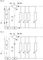
- THE figures 6 and 7 schematically represent the integration of such a lubrication module in a turbomachine lubrication system.
- FIG. 6 illustrates at least one lubrication station 84, in this case a plurality of such stations, typically in parallel with each other.
- These lubrication stations 84 are supplied with lubricant by a main lubrication circuit 86 and an auxiliary lubrication circuit 88.
- the lubrication module 50 comprises an intermediate reservoir 90.
- Each lubrication station 84 is connected to an outlet of the positive displacement pump 62, in this case both the outlet orifice 66b and the orifice discharge 68b (which are combined here in the diagram for the sake of clarity). Furthermore, the lubricant recoveries on each of the lubrication stations 84 converge towards the intermediate reservoir 90.
- the part of the circuit which extends from a common section at the outlet of the orifice outlet 66b and the discharge orifice 68b, and up to and including the intermediate reservoir 90, is common to the main lubrication circuit 86 and to the auxiliary lubrication circuit 88.
- the main lubrication circuit 86 also comprises a pump 92, driven by the turbomachine and configured to supply the main chamber 66 of the positive displacement pump 62, via the inlet orifice 66a. If necessary, a reservoir 94 can be provided on the main lubrication circuit 86.
- the auxiliary lubrication circuit 88 comprises a pipe 96 extending from the reservoir 90 to the inlet port 68a.
- the intermediate reservoir 90 is placed on the auxiliary lubrication circuit 88, between the lubrication station 84 and the positive displacement pump 62 in the direction of circulation of the lubricating fluid. Furthermore, the intermediate reservoir 90 is arranged between the lubrication station 84 and the pump 92 of the main lubrication circuit 86 in the direction of circulation of the lubricating fluid.
- FIG. 6 illustrates the inactive configuration of the piston 70: the turbomachine is at sufficient speed to power the pump 92, which therefore provides a flow rate and a pressure sufficient for filling the main chamber 66 beyond the predetermined threshold.
- the lubrication stations 84 are therefore supplied, via the main chamber 66, with lubricating fluid coming from the pump 92.
- the piston 70 prevents the circulation of fluid through the auxiliary chamber 68. Consequently, no fluid flows through the pipe 96.
- FIG. 7 illustrates, conversely, the active configuration of the piston 70: the speed of the turbomachine is not sufficient to power the pump 92.
- the active configuration corresponds to an autorotation phase of a fan of the turbomachine or to an idling rotation phase of the turbomachine.
- the pump 92 is substantially inactive, or at least its action does not make it possible to supply the lubrication stations 84 with lubricant. Its action therefore does not allow the main chamber 66 to be filled beyond the predetermined threshold.
- FIG 8 illustrates several possible installations of a positive displacement pump 62 in a turbomachine whose reduction gear 30 comprises an epicyclic gear train.
- the crown 30a is fixed and the planet carrier 30b forms the output of the reduction gear 30.
- the planet carrier 30b is integral in rotation with the propeller shaft 36, while the solar 30c is integral in rotation with the BP 34 turbine shaft.
- a volumetric pump 62a can be arranged so as to cooperate with the propeller shaft 36 (or more precisely a cam provided on this shaft), a volumetric pump 62b can be arranged so as to cooperate with the satellite carrier 30b, and/or a positive displacement pump 62c can be arranged so as to cooperate with the shaft connecting the solar 30c to the turbine shaft 34.
- the shaft with which the positive displacement pump cooperates with can be a shaft of the reduction gear 30 of the turbomachine 10.
- the positive displacement pumps 62a, 62b and 62c can be provided as alternatives to each other or in addition to each other.
- said pumps can optionally be arranged in phase shift around the shaft or shafts. Even if the shafts do not all have the same rotation speed (for example the propeller shaft 36 normally rotates less quickly than the LP turbine shaft 34), their rotation speeds are in phase due to the structure itself. of the reducer 30.
- the angular offset between two positive displacement pumps (or the corresponding cams, or the combination of the two), can be offset with respect to a period of the fastest rotating shaft.
- FIG. 9 illustrates several possible implementations of a volumetric pump 62, in a manner analogous to the figure 8 but in the case where the reduction gear 30 comprises a planetary train.
- the planet carrier 30b is fixed and the crown 30a forms the output of the reduction gear 30.
- the crown 30a is integral in rotation with the propeller shaft 36, while the solar 30c is integral in rotation of the BP 34 turbine shaft.
- a positive displacement pump 62a can be arranged so as to cooperate with the propeller shaft 36 (or more precisely a cam provided on this shaft), a positive displacement pump 62b can be arranged so as to cooperate with the crown 30a, and/or a positive displacement pump 62c can be arranged so as to cooperate with the turbine shaft 34. More generally, the shaft with which the positive displacement pump cooperates can be a shaft of the reduction gear 30 of the turbomachine 10.
- the present presentation has been described with reference to a specific exemplary embodiment, it is obvious that various modifications and changes can be made to these examples without departing from the scope.
- general of the invention for example, although an embodiment has been described in which the longitudinal direction AA corresponds to a radial direction of the turbomachine 10, other arrangements are possible: according to another example, the lubrication module 60 can be mounted from so that the longitudinal direction AA is parallel to an axial direction of the turbomachine 10. The lobes of the cam 52 can then project axially, or more generally in the longitudinal direction. Other directions are still possible.
- individual features of the different embodiments discussed may be combined in additional embodiments. Therefore, the description and drawings should be considered in an illustrative rather than a restrictive sense.
Landscapes
- Engineering & Computer Science (AREA)
- General Engineering & Computer Science (AREA)
- Mechanical Engineering (AREA)
- Chemical & Material Sciences (AREA)
- Combustion & Propulsion (AREA)
- Details Of Reciprocating Pumps (AREA)
Applications Claiming Priority (1)
| Application Number | Priority Date | Filing Date | Title |
|---|---|---|---|
| FR2205930A FR3136807B1 (fr) | 2022-06-17 | 2022-06-17 | Module de lubrification d’un poste de lubrification d’une turbomachine |
Publications (2)
| Publication Number | Publication Date |
|---|---|
| EP4293203A1 true EP4293203A1 (de) | 2023-12-20 |
| EP4293203B1 EP4293203B1 (de) | 2024-10-09 |
Family
ID=83188991
Family Applications (1)
| Application Number | Title | Priority Date | Filing Date |
|---|---|---|---|
| EP23178766.4A Active EP4293203B1 (de) | 2022-06-17 | 2023-06-12 | Schmiermodul einer schmierstation einer strömungsmaschine |
Country Status (3)
| Country | Link |
|---|---|
| US (1) | US12044137B2 (de) |
| EP (1) | EP4293203B1 (de) |
| FR (1) | FR3136807B1 (de) |
Citations (3)
| Publication number | Priority date | Publication date | Assignee | Title |
|---|---|---|---|---|
| FR2817912A1 (fr) | 2000-12-07 | 2002-06-14 | Hispano Suiza Sa | Reducteur reprenant les efforts axiaux generes par la soufflante d'un turboreacteur |
| FR3020410A1 (fr) | 2014-04-29 | 2015-10-30 | Snecma | Turbomachine d'aeronef a prelevement de puissance mecanique ameliore |
| FR3104208A1 (fr) * | 2019-12-06 | 2021-06-11 | Safran Aircraft Engines | Module de lubrification d’un réducteur de soufflante de turbomachine en phase d’autorotation de la soufflante |
Family Cites Families (34)
| Publication number | Priority date | Publication date | Assignee | Title |
|---|---|---|---|---|
| US2071913A (en) * | 1935-12-07 | 1937-02-23 | B F Sturtevant Company Inc | Lubrication system |
| US2642155A (en) * | 1948-05-14 | 1953-06-16 | Westinghouse Electric Corp | Lubrication apparatus |
| US2672010A (en) * | 1951-07-14 | 1954-03-16 | United Aircraft Corp | Pressurized lubrication system for gas turbines |
| US3130817A (en) * | 1959-09-09 | 1964-04-28 | Gunnar A Wahlmark | Lubrication mechanism for fluid device |
| US3443376A (en) * | 1967-08-04 | 1969-05-13 | Arco Corp | Engine control system and torque meter therefor |
| US3976165A (en) * | 1974-05-03 | 1976-08-24 | Norwalk-Turbo, Inc. | Lubricating and oil seal system for a high speed compressor |
| US4284174A (en) * | 1979-04-18 | 1981-08-18 | Avco Corporation | Emergency oil/mist system |
| JPH086875B2 (ja) * | 1988-02-03 | 1996-01-29 | 大同メタル工業株式会社 | 潤滑装置 |
| US4891934A (en) * | 1988-10-31 | 1990-01-09 | General Motors Corporation | Oil system for gas turbine engine |
| US5196746A (en) * | 1991-10-18 | 1993-03-23 | Sundstrand Corporation | Generator auxiliary forced cooling and lubrication system and method |
| US7118336B2 (en) * | 2003-12-19 | 2006-10-10 | Pratt & Whitney Canada Corp. | Pressurized oil supply for propeller engine system |
| EP2389532B1 (de) * | 2009-01-21 | 2019-02-27 | TF Hudgins Inc. | Hochdruckschmiersystem |
| US8944780B2 (en) * | 2011-03-25 | 2015-02-03 | Bayer Medical Care Inc. | Pumping devices, systems including multiple pistons and methods for use with medical fluids |
| US9151444B2 (en) * | 2012-10-01 | 2015-10-06 | FD Johnson Company | Dual-series feeder lubrication system |
| FR3019583B1 (fr) * | 2014-04-08 | 2019-09-13 | Safran Aircraft Engines | Isolation d'un reservoir de fluide combustible relativement a une partie aval de systeme d'alimentation pour turbomachine en cas d'incendie |
| FR3022300B1 (fr) * | 2014-06-11 | 2016-06-10 | Snecma | Dispositif de lubrification pour une turbomachine |
| JP6419223B2 (ja) * | 2015-02-06 | 2018-11-07 | 日立オートモティブシステムズ株式会社 | 可変容量形ポンプ |
| CN107709780B (zh) * | 2015-06-19 | 2019-08-16 | 日立汽车系统株式会社 | 可变容量型油泵 |
| WO2017026224A1 (ja) * | 2015-08-10 | 2017-02-16 | 日立オートモティブシステムズ株式会社 | 可変容量形オイルポンプ |
| US10161408B2 (en) * | 2015-10-29 | 2018-12-25 | United Technologies Corporation | Manhattan dual FDGS aux pump design |
| US11261946B2 (en) * | 2016-04-08 | 2022-03-01 | James L. O'Neill | Asymmetric cam transmission with coaxial counter rotating shafts |
| US10550997B2 (en) * | 2016-09-23 | 2020-02-04 | FD Johnson Company | Lubrication pump |
| WO2018123682A1 (ja) * | 2016-12-28 | 2018-07-05 | 日立オートモティブシステムズ株式会社 | オイルポンプ及びオイルポンプ一体型のバランサ装置 |
| JP2020073807A (ja) * | 2017-03-08 | 2020-05-14 | 日立オートモティブシステムズ株式会社 | バランサ装置とオイルポンプ及びバランサシャフト軸受部の潤滑システム |
| JP6885812B2 (ja) * | 2017-07-12 | 2021-06-16 | 株式会社山田製作所 | 油圧制御装置及び油圧制御方法 |
| JP7011972B2 (ja) * | 2018-04-27 | 2022-01-27 | 日立Astemo株式会社 | ギア、バランサ裝置、オイルポンプ付きバランサ裝置 |
| JP7116797B2 (ja) * | 2018-10-04 | 2022-08-10 | 日立Astemo株式会社 | オイルポンプ及び制御弁 |
| US11428163B2 (en) * | 2018-12-18 | 2022-08-30 | Raytheon Technologies Corporation | Two tier lubrication system |
| US11236637B2 (en) * | 2018-12-21 | 2022-02-01 | Raytheon Technologies Corporation | Auxiliary lubrication system with flow management valve |
| JP7273367B2 (ja) * | 2019-07-25 | 2023-05-15 | マツダ株式会社 | エンジンの潤滑装置 |
| US20210156280A1 (en) * | 2019-11-25 | 2021-05-27 | Rolls-Royce Corporation | Oil system with multi-tanks for split circuits |
| GB2592008A (en) * | 2020-02-11 | 2021-08-18 | Rolls Royce Plc | System for supplying lubricant to a component |
| GB202005916D0 (en) * | 2020-04-23 | 2020-06-10 | Rolls Royce Plc | Gas turbine engine lubrication system |
| US11732646B2 (en) * | 2021-07-06 | 2023-08-22 | Pratt & Whitney Canada Corp. | Lubrication system for a turbine engine |
-
2022
- 2022-06-17 FR FR2205930A patent/FR3136807B1/fr active Active
-
2023
- 2023-06-12 EP EP23178766.4A patent/EP4293203B1/de active Active
- 2023-06-16 US US18/336,674 patent/US12044137B2/en active Active
Patent Citations (3)
| Publication number | Priority date | Publication date | Assignee | Title |
|---|---|---|---|---|
| FR2817912A1 (fr) | 2000-12-07 | 2002-06-14 | Hispano Suiza Sa | Reducteur reprenant les efforts axiaux generes par la soufflante d'un turboreacteur |
| FR3020410A1 (fr) | 2014-04-29 | 2015-10-30 | Snecma | Turbomachine d'aeronef a prelevement de puissance mecanique ameliore |
| FR3104208A1 (fr) * | 2019-12-06 | 2021-06-11 | Safran Aircraft Engines | Module de lubrification d’un réducteur de soufflante de turbomachine en phase d’autorotation de la soufflante |
Also Published As
| Publication number | Publication date |
|---|---|
| US20230407765A1 (en) | 2023-12-21 |
| FR3136807A1 (fr) | 2023-12-22 |
| US12044137B2 (en) | 2024-07-23 |
| EP4293203B1 (de) | 2024-10-09 |
| FR3136807B1 (fr) | 2024-06-21 |
Similar Documents
| Publication | Publication Date | Title |
|---|---|---|
| EP3102795B1 (de) | Turbinenmotor mit einer schmiereinheit | |
| EP3956555B1 (de) | Reduktionsgetriebe einer turbomaschine | |
| EP3247924B1 (de) | Integration einer pumpe auf einem ritzelschaft | |
| WO2015166179A1 (fr) | Turbomachine d'aeronef a prelevement de puissance mecanique ameliore | |
| CA2947249A1 (fr) | Assemblage pour turbomachine d'aeronef et son procede de montage | |
| FR2977636A1 (fr) | Dispositif de lubrification d'un palier a roulement inter-arbres de turbopropulseur a double helice | |
| EP4073366B1 (de) | Aeronautisches antriebssystem mit niedriger leckrate und verbesserter antriebseffizienz | |
| WO2023247906A1 (fr) | Mecanisme de changement de pas avec verin entourant un palier de transfert de fluide | |
| EP4515094B1 (de) | Hilfsgetriebe und flugzeugturbinentriebwerk mit einem solchen getriebe | |
| EP4073371A1 (de) | Aeronautisches antriebssystem mit geringer leckflussrate und verbesserter antriebssystemseffizienz | |
| EP4293203B1 (de) | Schmiermodul einer schmierstation einer strömungsmaschine | |
| EP4127417B1 (de) | Fluggasturbinenaufbau welcher ein verbessertes schmiersystem eines ein gebläse antreibendes untersetzungsgetriebes umfasst | |
| FR3109963A1 (fr) | Module de lubrification d’un reducteur de soufflante de turbomachine en phase d’autorotation de la soufflante | |
| FR3156836A1 (fr) | Reducteur mecanique pour une turbomachine d’aeronef | |
| FR3141441A1 (fr) | Mécanisme de changement de pas à cinématique inversée | |
| WO2025176957A1 (fr) | Dispositif d'alimentation en huile pour un reducteur mecanique d'une turbomachine d'aeronef | |
| FR3137060A1 (fr) | Mécanisme de changement de pas avec vérin entourant un palier de transfert de fluide | |
| FR3141443A1 (fr) | Mécanisme de changement de pas avec vérin de commande et dispositif de verrouillage de pas hors des chambres du vérin | |
| FR3141442A1 (fr) | Mécanisme de changement de pas avec dispositif de verrouillage de pas en porte-à-faux | |
| FR3145588A1 (fr) | Turbomachine comprenant un reducteur de vitesse ayant des brides de fixation accouplees par un accouplement a dentures. | |
| EP4448382A1 (de) | Hydraulikbaugruppe für ein flugzeugtriebwerk |
Legal Events
| Date | Code | Title | Description |
|---|---|---|---|
| PUAI | Public reference made under article 153(3) epc to a published international application that has entered the european phase |
Free format text: ORIGINAL CODE: 0009012 |
|
| STAA | Information on the status of an ep patent application or granted ep patent |
Free format text: STATUS: REQUEST FOR EXAMINATION WAS MADE |
|
| 17P | Request for examination filed |
Effective date: 20230612 |
|
| AK | Designated contracting states |
Kind code of ref document: A1 Designated state(s): AL AT BE BG CH CY CZ DE DK EE ES FI FR GB GR HR HU IE IS IT LI LT LU LV MC ME MK MT NL NO PL PT RO RS SE SI SK SM TR |
|
| GRAP | Despatch of communication of intention to grant a patent |
Free format text: ORIGINAL CODE: EPIDOSNIGR1 |
|
| STAA | Information on the status of an ep patent application or granted ep patent |
Free format text: STATUS: GRANT OF PATENT IS INTENDED |
|
| INTG | Intention to grant announced |
Effective date: 20240502 |
|
| GRAS | Grant fee paid |
Free format text: ORIGINAL CODE: EPIDOSNIGR3 |
|
| GRAA | (expected) grant |
Free format text: ORIGINAL CODE: 0009210 |
|
| STAA | Information on the status of an ep patent application or granted ep patent |
Free format text: STATUS: THE PATENT HAS BEEN GRANTED |
|
| AK | Designated contracting states |
Kind code of ref document: B1 Designated state(s): AL AT BE BG CH CY CZ DE DK EE ES FI FR GB GR HR HU IE IS IT LI LT LU LV MC ME MK MT NL NO PL PT RO RS SE SI SK SM TR |
|
| REG | Reference to a national code |
Ref country code: CH Ref legal event code: EP |
|
| REG | Reference to a national code |
Ref country code: DE Ref legal event code: R096 Ref document number: 602023000695 Country of ref document: DE |
|
| REG | Reference to a national code |
Ref country code: IE Ref legal event code: FG4D Free format text: LANGUAGE OF EP DOCUMENT: FRENCH |
|
| REG | Reference to a national code |
Ref country code: LT Ref legal event code: MG9D |
|
| REG | Reference to a national code |
Ref country code: NL Ref legal event code: MP Effective date: 20241009 |
|
| REG | Reference to a national code |
Ref country code: AT Ref legal event code: MK05 Ref document number: 1730801 Country of ref document: AT Kind code of ref document: T Effective date: 20241009 |
|
| PG25 | Lapsed in a contracting state [announced via postgrant information from national office to epo] |
Ref country code: NL Free format text: LAPSE BECAUSE OF FAILURE TO SUBMIT A TRANSLATION OF THE DESCRIPTION OR TO PAY THE FEE WITHIN THE PRESCRIBED TIME-LIMIT Effective date: 20241009 |
|
| PG25 | Lapsed in a contracting state [announced via postgrant information from national office to epo] |
Ref country code: NL Free format text: LAPSE BECAUSE OF FAILURE TO SUBMIT A TRANSLATION OF THE DESCRIPTION OR TO PAY THE FEE WITHIN THE PRESCRIBED TIME-LIMIT Effective date: 20241009 |
|
| PG25 | Lapsed in a contracting state [announced via postgrant information from national office to epo] |
Ref country code: HR Free format text: LAPSE BECAUSE OF FAILURE TO SUBMIT A TRANSLATION OF THE DESCRIPTION OR TO PAY THE FEE WITHIN THE PRESCRIBED TIME-LIMIT Effective date: 20241009 Ref country code: IS Free format text: LAPSE BECAUSE OF FAILURE TO SUBMIT A TRANSLATION OF THE DESCRIPTION OR TO PAY THE FEE WITHIN THE PRESCRIBED TIME-LIMIT Effective date: 20250209 Ref country code: PT Free format text: LAPSE BECAUSE OF FAILURE TO SUBMIT A TRANSLATION OF THE DESCRIPTION OR TO PAY THE FEE WITHIN THE PRESCRIBED TIME-LIMIT Effective date: 20250210 |
|
| PG25 | Lapsed in a contracting state [announced via postgrant information from national office to epo] |
Ref country code: FI Free format text: LAPSE BECAUSE OF FAILURE TO SUBMIT A TRANSLATION OF THE DESCRIPTION OR TO PAY THE FEE WITHIN THE PRESCRIBED TIME-LIMIT Effective date: 20241009 |
|
| PG25 | Lapsed in a contracting state [announced via postgrant information from national office to epo] |
Ref country code: BG Free format text: LAPSE BECAUSE OF FAILURE TO SUBMIT A TRANSLATION OF THE DESCRIPTION OR TO PAY THE FEE WITHIN THE PRESCRIBED TIME-LIMIT Effective date: 20241009 |
|
| PG25 | Lapsed in a contracting state [announced via postgrant information from national office to epo] |
Ref country code: ES Free format text: LAPSE BECAUSE OF FAILURE TO SUBMIT A TRANSLATION OF THE DESCRIPTION OR TO PAY THE FEE WITHIN THE PRESCRIBED TIME-LIMIT Effective date: 20241009 |
|
| PG25 | Lapsed in a contracting state [announced via postgrant information from national office to epo] |
Ref country code: NO Free format text: LAPSE BECAUSE OF FAILURE TO SUBMIT A TRANSLATION OF THE DESCRIPTION OR TO PAY THE FEE WITHIN THE PRESCRIBED TIME-LIMIT Effective date: 20250109 |
|
| PG25 | Lapsed in a contracting state [announced via postgrant information from national office to epo] |
Ref country code: LV Free format text: LAPSE BECAUSE OF FAILURE TO SUBMIT A TRANSLATION OF THE DESCRIPTION OR TO PAY THE FEE WITHIN THE PRESCRIBED TIME-LIMIT Effective date: 20241009 Ref country code: GR Free format text: LAPSE BECAUSE OF FAILURE TO SUBMIT A TRANSLATION OF THE DESCRIPTION OR TO PAY THE FEE WITHIN THE PRESCRIBED TIME-LIMIT Effective date: 20250110 Ref country code: AT Free format text: LAPSE BECAUSE OF FAILURE TO SUBMIT A TRANSLATION OF THE DESCRIPTION OR TO PAY THE FEE WITHIN THE PRESCRIBED TIME-LIMIT Effective date: 20241009 |
|
| PG25 | Lapsed in a contracting state [announced via postgrant information from national office to epo] |
Ref country code: PL Free format text: LAPSE BECAUSE OF FAILURE TO SUBMIT A TRANSLATION OF THE DESCRIPTION OR TO PAY THE FEE WITHIN THE PRESCRIBED TIME-LIMIT Effective date: 20241009 |
|
| PG25 | Lapsed in a contracting state [announced via postgrant information from national office to epo] |
Ref country code: RS Free format text: LAPSE BECAUSE OF FAILURE TO SUBMIT A TRANSLATION OF THE DESCRIPTION OR TO PAY THE FEE WITHIN THE PRESCRIBED TIME-LIMIT Effective date: 20250109 |
|
| PG25 | Lapsed in a contracting state [announced via postgrant information from national office to epo] |
Ref country code: SM Free format text: LAPSE BECAUSE OF FAILURE TO SUBMIT A TRANSLATION OF THE DESCRIPTION OR TO PAY THE FEE WITHIN THE PRESCRIBED TIME-LIMIT Effective date: 20241009 |
|
| PGFP | Annual fee paid to national office [announced via postgrant information from national office to epo] |
Ref country code: DE Payment date: 20250618 Year of fee payment: 3 |
|
| PG25 | Lapsed in a contracting state [announced via postgrant information from national office to epo] |
Ref country code: DK Free format text: LAPSE BECAUSE OF FAILURE TO SUBMIT A TRANSLATION OF THE DESCRIPTION OR TO PAY THE FEE WITHIN THE PRESCRIBED TIME-LIMIT Effective date: 20241009 |
|
| REG | Reference to a national code |
Ref country code: DE Ref legal event code: R097 Ref document number: 602023000695 Country of ref document: DE |
|
| PG25 | Lapsed in a contracting state [announced via postgrant information from national office to epo] |
Ref country code: EE Free format text: LAPSE BECAUSE OF FAILURE TO SUBMIT A TRANSLATION OF THE DESCRIPTION OR TO PAY THE FEE WITHIN THE PRESCRIBED TIME-LIMIT Effective date: 20241009 |
|
| PGFP | Annual fee paid to national office [announced via postgrant information from national office to epo] |
Ref country code: FR Payment date: 20250623 Year of fee payment: 3 |
|
| PG25 | Lapsed in a contracting state [announced via postgrant information from national office to epo] |
Ref country code: RO Free format text: LAPSE BECAUSE OF FAILURE TO SUBMIT A TRANSLATION OF THE DESCRIPTION OR TO PAY THE FEE WITHIN THE PRESCRIBED TIME-LIMIT Effective date: 20241009 |
|
| PG25 | Lapsed in a contracting state [announced via postgrant information from national office to epo] |
Ref country code: SK Free format text: LAPSE BECAUSE OF FAILURE TO SUBMIT A TRANSLATION OF THE DESCRIPTION OR TO PAY THE FEE WITHIN THE PRESCRIBED TIME-LIMIT Effective date: 20241009 |
|
| PG25 | Lapsed in a contracting state [announced via postgrant information from national office to epo] |
Ref country code: CZ Free format text: LAPSE BECAUSE OF FAILURE TO SUBMIT A TRANSLATION OF THE DESCRIPTION OR TO PAY THE FEE WITHIN THE PRESCRIBED TIME-LIMIT Effective date: 20241009 |
|
| PG25 | Lapsed in a contracting state [announced via postgrant information from national office to epo] |
Ref country code: IT Free format text: LAPSE BECAUSE OF FAILURE TO SUBMIT A TRANSLATION OF THE DESCRIPTION OR TO PAY THE FEE WITHIN THE PRESCRIBED TIME-LIMIT Effective date: 20241009 |
|
| PLBE | No opposition filed within time limit |
Free format text: ORIGINAL CODE: 0009261 |
|
| STAA | Information on the status of an ep patent application or granted ep patent |
Free format text: STATUS: NO OPPOSITION FILED WITHIN TIME LIMIT |
|
| PG25 | Lapsed in a contracting state [announced via postgrant information from national office to epo] |
Ref country code: SE Free format text: LAPSE BECAUSE OF FAILURE TO SUBMIT A TRANSLATION OF THE DESCRIPTION OR TO PAY THE FEE WITHIN THE PRESCRIBED TIME-LIMIT Effective date: 20241009 |
|
| 26N | No opposition filed |
Effective date: 20250710 |
|
| PG25 | Lapsed in a contracting state [announced via postgrant information from national office to epo] |
Ref country code: MC Free format text: LAPSE BECAUSE OF FAILURE TO SUBMIT A TRANSLATION OF THE DESCRIPTION OR TO PAY THE FEE WITHIN THE PRESCRIBED TIME-LIMIT Effective date: 20241009 |
|
| PG25 | Lapsed in a contracting state [announced via postgrant information from national office to epo] |
Ref country code: LU Free format text: LAPSE BECAUSE OF NON-PAYMENT OF DUE FEES Effective date: 20250612 |
|
| REG | Reference to a national code |
Ref country code: BE Ref legal event code: MM Effective date: 20250630 |
|
| PG25 | Lapsed in a contracting state [announced via postgrant information from national office to epo] |
Ref country code: IE Free format text: LAPSE BECAUSE OF NON-PAYMENT OF DUE FEES Effective date: 20250612 |
|
| PG25 | Lapsed in a contracting state [announced via postgrant information from national office to epo] |
Ref country code: BE Free format text: LAPSE BECAUSE OF NON-PAYMENT OF DUE FEES Effective date: 20250630 |