EP4293219A1 - Système de fixation destiné à l'agencement des boulons dans un ensemble tour - Google Patents
Système de fixation destiné à l'agencement des boulons dans un ensemble tour Download PDFInfo
- Publication number
- EP4293219A1 EP4293219A1 EP22382573.8A EP22382573A EP4293219A1 EP 4293219 A1 EP4293219 A1 EP 4293219A1 EP 22382573 A EP22382573 A EP 22382573A EP 4293219 A1 EP4293219 A1 EP 4293219A1
- Authority
- EP
- European Patent Office
- Prior art keywords
- fastening system
- belt
- tower
- bolt
- support unit
- Prior art date
- Legal status (The legal status is an assumption and is not a legal conclusion. Google has not performed a legal analysis and makes no representation as to the accuracy of the status listed.)
- Withdrawn
Links
- 238000009434 installation Methods 0.000 claims abstract description 15
- 238000000034 method Methods 0.000 claims abstract description 14
- 230000007246 mechanism Effects 0.000 claims description 10
- 238000003780 insertion Methods 0.000 claims description 5
- 230000037431 insertion Effects 0.000 claims description 5
- 239000007779 soft material Substances 0.000 claims description 5
- 230000003028 elevating effect Effects 0.000 description 7
- 230000014759 maintenance of location Effects 0.000 description 3
- 239000000463 material Substances 0.000 description 3
- 238000012986 modification Methods 0.000 description 3
- 230000004048 modification Effects 0.000 description 3
- 239000004033 plastic Substances 0.000 description 3
- 230000008569 process Effects 0.000 description 3
- 239000004677 Nylon Substances 0.000 description 1
- 238000004026 adhesive bonding Methods 0.000 description 1
- 230000000903 blocking effect Effects 0.000 description 1
- 230000008859 change Effects 0.000 description 1
- 239000011248 coating agent Substances 0.000 description 1
- 238000000576 coating method Methods 0.000 description 1
- 230000008878 coupling Effects 0.000 description 1
- 238000010168 coupling process Methods 0.000 description 1
- 238000005859 coupling reaction Methods 0.000 description 1
- 230000001419 dependent effect Effects 0.000 description 1
- 238000011161 development Methods 0.000 description 1
- 230000018109 developmental process Effects 0.000 description 1
- 239000004744 fabric Substances 0.000 description 1
- 238000011900 installation process Methods 0.000 description 1
- 229920001778 nylon Polymers 0.000 description 1
- 239000003973 paint Substances 0.000 description 1
- 229920000728 polyester Polymers 0.000 description 1
- 238000009877 rendering Methods 0.000 description 1
- 230000000717 retained effect Effects 0.000 description 1
Images



Classifications
-
- F—MECHANICAL ENGINEERING; LIGHTING; HEATING; WEAPONS; BLASTING
- F03—MACHINES OR ENGINES FOR LIQUIDS; WIND, SPRING, OR WEIGHT MOTORS; PRODUCING MECHANICAL POWER OR A REACTIVE PROPULSIVE THRUST, NOT OTHERWISE PROVIDED FOR
- F03D—WIND MOTORS
- F03D13/00—Assembly, mounting or commissioning of wind motors; Arrangements specially adapted for transporting wind motor components
- F03D13/10—Assembly of wind motors; Arrangements for erecting wind motors
- F03D13/112—Assembly of wind motors; Arrangements for erecting wind motors of towers; of masts
-
- F—MECHANICAL ENGINEERING; LIGHTING; HEATING; WEAPONS; BLASTING
- F03—MACHINES OR ENGINES FOR LIQUIDS; WIND, SPRING, OR WEIGHT MOTORS; PRODUCING MECHANICAL POWER OR A REACTIVE PROPULSIVE THRUST, NOT OTHERWISE PROVIDED FOR
- F03D—WIND MOTORS
- F03D13/00—Assembly, mounting or commissioning of wind motors; Arrangements specially adapted for transporting wind motor components
- F03D13/20—Arrangements for mounting or supporting wind motors; Masts or towers for wind motors
- F03D13/201—Towers
- F03D13/205—Connection means, e.g. joints between segments
-
- F—MECHANICAL ENGINEERING; LIGHTING; HEATING; WEAPONS; BLASTING
- F03—MACHINES OR ENGINES FOR LIQUIDS; WIND, SPRING, OR WEIGHT MOTORS; PRODUCING MECHANICAL POWER OR A REACTIVE PROPULSIVE THRUST, NOT OTHERWISE PROVIDED FOR
- F03D—WIND MOTORS
- F03D80/00—Details, components or accessories not provided for in groups F03D1/00 - F03D17/00
- F03D80/80—Arrangement of components within nacelles or towers
- F03D80/88—Arrangement of components within nacelles or towers of mechanical components
-
- F—MECHANICAL ENGINEERING; LIGHTING; HEATING; WEAPONS; BLASTING
- F16—ENGINEERING ELEMENTS AND UNITS; GENERAL MEASURES FOR PRODUCING AND MAINTAINING EFFECTIVE FUNCTIONING OF MACHINES OR INSTALLATIONS; THERMAL INSULATION IN GENERAL
- F16B—DEVICES FOR FASTENING OR SECURING CONSTRUCTIONAL ELEMENTS OR MACHINE PARTS TOGETHER, e.g. NAILS, BOLTS, CIRCLIPS, CLAMPS, CLIPS OR WEDGES; JOINTS OR JOINTING
- F16B2/00—Friction-grip releasable fastenings
- F16B2/02—Clamps, i.e. with gripping action effected by positive means other than the inherent resistance to deformation of the material of the fastening
- F16B2/06—Clamps, i.e. with gripping action effected by positive means other than the inherent resistance to deformation of the material of the fastening external, i.e. with contracting action
- F16B2/08—Clamps, i.e. with gripping action effected by positive means other than the inherent resistance to deformation of the material of the fastening external, i.e. with contracting action using bands
-
- F—MECHANICAL ENGINEERING; LIGHTING; HEATING; WEAPONS; BLASTING
- F16—ENGINEERING ELEMENTS AND UNITS; GENERAL MEASURES FOR PRODUCING AND MAINTAINING EFFECTIVE FUNCTIONING OF MACHINES OR INSTALLATIONS; THERMAL INSULATION IN GENERAL
- F16B—DEVICES FOR FASTENING OR SECURING CONSTRUCTIONAL ELEMENTS OR MACHINE PARTS TOGETHER, e.g. NAILS, BOLTS, CIRCLIPS, CLAMPS, CLIPS OR WEDGES; JOINTS OR JOINTING
- F16B2/00—Friction-grip releasable fastenings
- F16B2/02—Clamps, i.e. with gripping action effected by positive means other than the inherent resistance to deformation of the material of the fastening
- F16B2/06—Clamps, i.e. with gripping action effected by positive means other than the inherent resistance to deformation of the material of the fastening external, i.e. with contracting action
- F16B2/10—Clamps, i.e. with gripping action effected by positive means other than the inherent resistance to deformation of the material of the fastening external, i.e. with contracting action using pivoting jaws
-
- F—MECHANICAL ENGINEERING; LIGHTING; HEATING; WEAPONS; BLASTING
- F16—ENGINEERING ELEMENTS AND UNITS; GENERAL MEASURES FOR PRODUCING AND MAINTAINING EFFECTIVE FUNCTIONING OF MACHINES OR INSTALLATIONS; THERMAL INSULATION IN GENERAL
- F16B—DEVICES FOR FASTENING OR SECURING CONSTRUCTIONAL ELEMENTS OR MACHINE PARTS TOGETHER, e.g. NAILS, BOLTS, CIRCLIPS, CLAMPS, CLIPS OR WEDGES; JOINTS OR JOINTING
- F16B27/00—Bolts, screws, or nuts formed in integral series but easily separable, particularly for use in automatic machines
-
- F—MECHANICAL ENGINEERING; LIGHTING; HEATING; WEAPONS; BLASTING
- F16—ENGINEERING ELEMENTS AND UNITS; GENERAL MEASURES FOR PRODUCING AND MAINTAINING EFFECTIVE FUNCTIONING OF MACHINES OR INSTALLATIONS; THERMAL INSULATION IN GENERAL
- F16B—DEVICES FOR FASTENING OR SECURING CONSTRUCTIONAL ELEMENTS OR MACHINE PARTS TOGETHER, e.g. NAILS, BOLTS, CIRCLIPS, CLAMPS, CLIPS OR WEDGES; JOINTS OR JOINTING
- F16B7/00—Connections of rods or tubes, e.g. of non-circular section, mutually, including resilient connections
- F16B7/18—Connections of rods or tubes, e.g. of non-circular section, mutually, including resilient connections using screw-thread elements
- F16B7/182—Connections of rods or tubes, e.g. of non-circular section, mutually, including resilient connections using screw-thread elements for coaxial connections of two rods or tubes
-
- F—MECHANICAL ENGINEERING; LIGHTING; HEATING; WEAPONS; BLASTING
- F05—INDEXING SCHEMES RELATING TO ENGINES OR PUMPS IN VARIOUS SUBCLASSES OF CLASSES F01-F04
- F05B—INDEXING SCHEME RELATING TO WIND, SPRING, WEIGHT, INERTIA OR LIKE MOTORS, TO MACHINES OR ENGINES FOR LIQUIDS COVERED BY SUBCLASSES F03B, F03D AND F03G
- F05B2230/00—Manufacture
- F05B2230/60—Assembly methods
-
- F—MECHANICAL ENGINEERING; LIGHTING; HEATING; WEAPONS; BLASTING
- F05—INDEXING SCHEMES RELATING TO ENGINES OR PUMPS IN VARIOUS SUBCLASSES OF CLASSES F01-F04
- F05B—INDEXING SCHEME RELATING TO WIND, SPRING, WEIGHT, INERTIA OR LIKE MOTORS, TO MACHINES OR ENGINES FOR LIQUIDS COVERED BY SUBCLASSES F03B, F03D AND F03G
- F05B2260/00—Function
- F05B2260/30—Retaining components in desired mutual position
- F05B2260/301—Retaining bolts or nuts
-
- F—MECHANICAL ENGINEERING; LIGHTING; HEATING; WEAPONS; BLASTING
- F16—ENGINEERING ELEMENTS AND UNITS; GENERAL MEASURES FOR PRODUCING AND MAINTAINING EFFECTIVE FUNCTIONING OF MACHINES OR INSTALLATIONS; THERMAL INSULATION IN GENERAL
- F16B—DEVICES FOR FASTENING OR SECURING CONSTRUCTIONAL ELEMENTS OR MACHINE PARTS TOGETHER, e.g. NAILS, BOLTS, CIRCLIPS, CLAMPS, CLIPS OR WEDGES; JOINTS OR JOINTING
- F16B41/00—Measures against loss of bolts, nuts, or pins; Measures against unauthorised operation of bolts, nuts or pins
- F16B41/002—Measures against loss of bolts, nuts or pins
-
- Y—GENERAL TAGGING OF NEW TECHNOLOGICAL DEVELOPMENTS; GENERAL TAGGING OF CROSS-SECTIONAL TECHNOLOGIES SPANNING OVER SEVERAL SECTIONS OF THE IPC; TECHNICAL SUBJECTS COVERED BY FORMER USPC CROSS-REFERENCE ART COLLECTIONS [XRACs] AND DIGESTS
- Y02—TECHNOLOGIES OR APPLICATIONS FOR MITIGATION OR ADAPTATION AGAINST CLIMATE CHANGE
- Y02E—REDUCTION OF GREENHOUSE GAS [GHG] EMISSIONS, RELATED TO ENERGY GENERATION, TRANSMISSION OR DISTRIBUTION
- Y02E10/00—Energy generation through renewable energy sources
- Y02E10/70—Wind energy
- Y02E10/72—Wind turbines with rotation axis in wind direction
Definitions
- the present invention relates to a fastening system for arranging bolts in a tower assembly.
- the invention also relates to a method for installing bolts in a tower assembly.
- outer flanges In the field of wind turbines, some wind turbines have segmented towers and in order to join two tower sections, outer flanges are used. Such outer flanges have a plurality of holes. The outer flange of one tower section is connected to the outer flange of another tower section by means of bolts thereby joining both tower sections.
- a mobile elevating work platform In order to carry the bolts from ground to its final position, a mobile elevating work platform is used wherein a technician stays to inserts the bolts one by one by hand into a corresponding assembling hole.
- the outer flange has typically about 170 - 200 holes.
- two technicians are required.
- the mobile elevating work platform has a low weight capacity.
- the basket of the mobile elevating working platform can only carry 7 - 10 bolts, requiring several travels to finalize the task.
- this technique requires a huge amount of time due the low weight capacity of the mobile elevating work platform.
- Another known solution comprises placing a plastic protection inside each assembling hole of the flange before performing the erection of the tower section, in order to protect and hold the bolts in place.
- a typical disadvantage of such known solutions is that a considerable amount of time is required to arrange and secure the bolts within the corresponding assembling holes.
- a bolt may fall during the erection of the tower which may cause a severe accident, e.g. if a bolt falls and hit a technician.
- the support unit is configured to be attached to the belt.
- the at least one clamping element is configured to retain a bolt therein.
- the fixing plate is arranged in the support unit and is configured to be moved from a closed position in which the bolt is to be secured and an open position to allow the insertion/removal of the bolt in/from the at least one clamping element.
- the at least one retaining mean is movable from a first position to a second position in which the retaining mean connects the fixing plate and the support unit thereby further securing the bolt within the at least one clamping element.
- At least one bolt is arranged into the fastening system and is moved together with the tower section when is lifted until assembly stage.
- the safety is increased as the at least one bolt is securely fixed on position within the fastening system without any risk of fall during the performance of the task, thus preventing the bolt from fall during work at height and cause a severe accident to technicians.
- the at least one clamping element may be a single piece.
- the clamping element may comprise two separate pieces.
- the clamping element may be made of a soft material to allow different size bolts to be arranged therein tightly without causing any damage.
- the fixing plate may further comprise a pivoting pin connecting the fixing plate to the support unit and thereby enabling the fixing plate to rotate with respect to the support unit.
- a pivoting pin facilitates releasing or introducing a bolt within the at least one clamping element which facilitates the installation process and further reduces the installation time.
- the fixing plate may further comprise a locking pin for releasably locking the fastening device to the belt.
- the locking pin allows blocking the position of the fastening device on a determined position on the belt and therefore a more versatile system may be obtained.
- the retaining mean may be a bar, a lever or a crowbar.
- the support unit may further comprise a hole configured to allow the belt to be inserted therein, thereby allowing the support unit to be movable along the belt.
- the support unit may be fixedly attached to the belt.
- the fastening system may further comprise a plurality of fastening devices.
- the number of travels the mobile elevating work platform must realize up and down is reduced rendering the fastening system safer as the technicians have to work in height less time. Additionally, the safety is increased as all the bolts are securely fixed on position within the fastening system thus preventing the bolt from fall during work at height and cause a severe accident to technicians.
- having a plurality of fastening devices enables adapting the fastening system to the number of bolts required for a specific tower flange, that is, a more versatile system may be obtained.
- each fastening device may carry one bolt, the capacity of bolts at the fastening system will match to the number of fastening devices. Therefore, the number of fastening devices may be adapted to the number of assembling holes of the tower flange.
- the tower flange may be a projecting rim or collar that protrudes from the tower section.
- the flanges may be part of the tower section or may be a separated piece and may serve to hold it in place and to give additional strength and/or stiffness. Additionally, it may be a supporting area which may provide a place for the attachment of other objects, e.g. another tower section.
- the tower flange may have assembling holes. The assembling holes of a tower flange may match with the assembling holes of the next tower section, wherein the tower sections may then be fixed to each other by introducing bolts in the assembling holes to adjoin the two tower sections.
- a method of installing bolts in a wind turbine tower with a segmented tower, having the segmented tower at least two tower sections, each tower section with a corresponding flange having a plurality of assembling holes, is provided.
- a fastening system according to any of the examples described herein may be provided.
- the fastening system comprises a belt and at least one fastening device.
- the belt comprises securing means configured to tie the belt around the outer part of a wind turbine tower.
- the fastening device comprises a support unit, at least one clamping element, a fixing plate, and at least one retaining mean as described above.
- a bolt is provided.
- the bolt is inserted into the at least one clamping element of the at least one fastening device.
- the bolt is then secured within the at least one clamping element by rotating it in the opposite direction to hold the bolt tight and the at least one retaining mean is rotated in the opposite direction to a closed position to further secure the bolt therein.
- the belt is then arranged around the outer part of the tower section and tying thereto via the securing means.
- the tower section is then lifted and placed it in a predetermined assembling position.
- the assembling holes of the flanges of two tower section e.g. a pre-installed tower section and subsequent tower section, are aligned.
- the tower sections may be placed above a previous installed tower section previously. Once both sections are aligned, the bolts may be placed in corresponding assembling holes.
- the bolt is removed from the fastening device by rotating the retaining mean into the open position and the at least one clamping device is rotated to release the bolt.
- the bolt then is inserted in the corresponding assembling hole of the tower flange of the tower section.
- the belt is removed from the tower section.
- this method By using this method, the technicians do not have to carry the bolts in the mobile elevating work platform, which due to the low weight capacity cannot carry all the bolts in one operation. Therefore, the amount of operations that the technicians have to do is reduced to a one-time operation. Thus, this method is more efficient as reduces the time of performing the task and increase the safety as the time that the technicians have to work on heights is also reduced.
- Fig. 1 depicts a wind turbine 10 with a segmented tower 2 comprising a plurality, e.g. four, tower sections 20, 30, 40, 50.
- Each tower section may comprise at least an outwardly protruding flange 22, 31, 32, 41, 42, 51.
- each tower section may comprise a flange at each end, for example, tower section 40 may comprise flanges 41, 42.
- the flanges 22, 31, 32, 41, 42, 51 may have a plurality of assembling holes (not shown)configured to receive bolts.
- the flanges 22, 31, 32, 41, 42, 51 may be used to join two tower sections together.
- the tower section 30 may be joined to a previously erected tower section 20 via flanges 31 and 22 respectively. That is, during installation, the tower section 30 may be positioned on top of previously erected tower section 20, and then, the towers sections 20, 30 may be aligned i.e. the assembling holes of the respective flanges 22, 31 may be aligned.
- the tower sections 20- 30 may then be fixed to each other by introducing bolts 400 in the assembling holes.
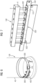
- Fig. 2 depicts a fastening system 100 e.g. to carry at least a bolt 400 during the installation of a segmented tower 20.
- the fastening system 100 may comprise a belt 200 and a fastening device 300 (see figure 3 ).
- the belt 200 may be made of a strong, durable and/or resistant material capable to carry the weight of the bolts properly secured and at the same time keep the belt 200 tied to/around the tower section during transportation and lifting.
- the belt 200 may be flexible and long enough to may be tied around the tower section 30.
- the belt may be made of nylon or polyester fabric.
- the belt may comprise securing means, e.g. a ratchet mechanism (not shown), to be secured to the tower.
- the fastening device 300 may comprise a support unit 310, at least one clamping element 320, at least one fixing plate 330 330, at least one retaining mean 340, a pivoting pin 350, a locking pin 360 as shown in Fig 2 .
- the support unit 310 may serve to support the at least one clamping element 320.
- the support unit 310 may have a first and a second installation holes so the fixing plate 330 may be pivotally mounted.
- the support unit 310 may be configured to be attached to the belt 200.
- the support unit 310 may have an inserting hole being configured to allow the belt 200 to be inserted therein, thereby allowing the support unit 310 to be movable along the belt.
- the support unit 310 may be fixed to the belt 200 e.g. by gluing it or with mechanical means such as screws. In those examples case, the support unit 310 may have a fixed position and may be not able to be moved along the belt 200.
- the at least one clamping element 320 that may be configured to retain a bolt 400 therein.
- the at least one clamping element 320 may be a single piece with a U-shape or may comprise two separate pieces joined together forming a U-shape.
- the U-shape may improve the retention of the bolt 400 tighter, as may hold most part of the bolt 400 and may leave a gap to remove the bolt 400 easily.
- the at least one clamping element 320 may be made of a soft material e.g. rubber.
- the at least one clamping element 320 may be positioned in the support unit 310.
- the at least one clamping element 320 may have a fixing hole which may serve to connect it to the fixing plate 330 and may have a retaining hole wherein the at least one retaining mean 340 may be pivotally mounted to facilitate the insertion or removal of the bolt 400.
- the fixing plate 330 may allow the at least one clamping element 320 to rotate around the support unit 310 to facilitate the insertion or removal of the bolt 400.
- the fixing plate 330 may be pivotally mounted in the support unit 310 and may be also be coupled to the at least one clamping element 320, thereby enabling the at least one clamping element 320 to rotate around the support unit 310.
- the fixing plate 330 may further have a pivoting slot and a locking slot matching with the first and second installation holes of the support unit 310, respectively.
- the fixing plate 330 may further comprise a clamping slot and a retaining slot, which may match and may be aligned with the fixing hole and the retaining hole of the at least one clamping element 320.
- Two pins may be introduced and may join the fixing plate 330 to the at least one clamping element 320.
- One of the pins may further join the retaining mean 340 with the at least one clamping element, enabling the retaining mean 340 to rotate in respect of the at least one clamping element 320.
- the fastening device 300 may further comprise a pivoting pin 350 for pivotally coupling the at least one clamping element 320 to the support unit 310 with the fixing plate 330.
- the fixing plate 330 may have a pivoting slot matching with the first installation hole of the support unit 310, wherein the pivoting slot and the first installation hole may be aligned and the pivoting pin 350 may be introduced to connect the fixing plate 330 with the support unit 310. Therefore, the pivoting pin 350 may enable the fixing plate 330 to rotate with respect to the support unit 310.
- the fixing plate 330 may have at least two positions: an open position and a closed position. The fixing plate 330 may be configured to be moved from the closed position to the open position.
- Fig. 6 depicts a fastening system 100 arranged in a tower section 40.
- the fastening system 100 may be secured to the tower section 40 with securing means 210 e.g. a ratchet mechanism.
- the bolts 400 may be arranged into the fastening devices 300 before arranging the fastening system 100 to the tower section 40.
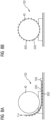
- Fig. 8B depicts the belt 200 arranged in the tower section 40.
- the belt 200 may be secured via securing means 210 e.g. a ratchet mechanism.
- Fig. 9 shows a flow chart of a method 900 for the installation of bolts 400-405 in a wind turbine 10 with a segmented tower 20.
- a fastening system 100 may, in box 901, be provided.
- a bolt may, in box 902, be provided.
- the bolt may, in box 903, be inserted into the at least one clamping element of the at least one fastening device.
- the bolt may, in box 904, be secured within the at least one clamping element by moving the retaining mean of the at least one fastening device to a closed position.
- the belt may, in box 905, be arranged around the outer part of the tower section and tied thereto via the securing means e.g. by closing the ratchet mechanism.
- the tower section may, in box 906, be lifted and be placed in a predetermined assembling position.
- the tower sections may be placed above a previous installed tower section previously, wherein the two tower sections may be aligned.
- the assembling holes of the flanges of two tower section e.g. a pre-installed tower section and subsequent tower section, are aligned. Once both sections are aligned, the bolts may be placed in corresponding assembling holes.
- the bolt may, in box 907, be inserted in the corresponding assembling hole of the tower flange of the tower section.
- the bolt may be secured with a securing means e.g. a washer and a nut. In case of having a plurality of bolts, this step may be repeated for each bolt.
- the belt may be removed from the tower section by tampering the securing means e.g. by opening the ratchet mechanism.
Landscapes
- Engineering & Computer Science (AREA)
- General Engineering & Computer Science (AREA)
- Mechanical Engineering (AREA)
- Life Sciences & Earth Sciences (AREA)
- Sustainable Development (AREA)
- Sustainable Energy (AREA)
- Chemical & Material Sciences (AREA)
- Combustion & Propulsion (AREA)
- Wind Motors (AREA)
- Clamps And Clips (AREA)
Priority Applications (5)
| Application Number | Priority Date | Filing Date | Title |
|---|---|---|---|
| EP22382573.8A EP4293219A1 (fr) | 2022-06-15 | 2022-06-15 | Système de fixation destiné à l'agencement des boulons dans un ensemble tour |
| PCT/EP2023/064474 WO2023241908A1 (fr) | 2022-06-15 | 2023-05-31 | Système de fixation servant à agencer des boulons dans un ensemble tour |
| EP23730401.9A EP4508325B1 (fr) | 2022-06-15 | 2023-05-31 | Système de fixation destiné à l'agencement des boulons dans un ensemble de tour |
| ES23730401T ES3054585T3 (en) | 2022-06-15 | 2023-05-31 | Fastening system for arranging bolts in a tower assembly |
| CN202380046752.9A CN119384556A (zh) | 2022-06-15 | 2023-05-31 | 用于在塔架组件中布置螺栓的紧固系统 |
Applications Claiming Priority (1)
| Application Number | Priority Date | Filing Date | Title |
|---|---|---|---|
| EP22382573.8A EP4293219A1 (fr) | 2022-06-15 | 2022-06-15 | Système de fixation destiné à l'agencement des boulons dans un ensemble tour |
Publications (1)
| Publication Number | Publication Date |
|---|---|
| EP4293219A1 true EP4293219A1 (fr) | 2023-12-20 |
Family
ID=82117683
Family Applications (2)
| Application Number | Title | Priority Date | Filing Date |
|---|---|---|---|
| EP22382573.8A Withdrawn EP4293219A1 (fr) | 2022-06-15 | 2022-06-15 | Système de fixation destiné à l'agencement des boulons dans un ensemble tour |
| EP23730401.9A Active EP4508325B1 (fr) | 2022-06-15 | 2023-05-31 | Système de fixation destiné à l'agencement des boulons dans un ensemble de tour |
Family Applications After (1)
| Application Number | Title | Priority Date | Filing Date |
|---|---|---|---|
| EP23730401.9A Active EP4508325B1 (fr) | 2022-06-15 | 2023-05-31 | Système de fixation destiné à l'agencement des boulons dans un ensemble de tour |
Country Status (4)
| Country | Link |
|---|---|
| EP (2) | EP4293219A1 (fr) |
| CN (1) | CN119384556A (fr) |
| ES (1) | ES3054585T3 (fr) |
| WO (1) | WO2023241908A1 (fr) |
Cited By (1)
| Publication number | Priority date | Publication date | Assignee | Title |
|---|---|---|---|---|
| CN120576037A (zh) * | 2025-07-18 | 2025-09-02 | 华能安徽蒙城风力发电有限责任公司 | 一种风电混塔预制塔筒节连接结构 |
Citations (6)
| Publication number | Priority date | Publication date | Assignee | Title |
|---|---|---|---|---|
| EP2927485A1 (fr) * | 2014-03-31 | 2015-10-07 | Alstom Renovables España, S.L. | Alignement des composants de turbine éolienne |
| WO2018153522A1 (fr) * | 2017-02-23 | 2018-08-30 | Siemens Wind Power A/S | Dispositif d'aide à l'assemblage pour aider à l'assemblage de deux composants d'éolienne d'une éolienne et procédé d'assemblage des deux composants d'éolienne |
| EP3394432B1 (fr) * | 2015-12-22 | 2020-02-12 | Vestas Wind Systems A/S | Moyeu de rotor pour une éolienne ayant des éléments de fixation pré-positionnés et procédé associé |
| TWI689667B (zh) * | 2019-06-24 | 2020-04-01 | 光柘企業有限公司 | 螺絲釘載帶 |
| CN111810367A (zh) * | 2020-07-23 | 2020-10-23 | 明阳智慧能源集团股份公司 | 一种用于风电机组扰流条安装和拆卸的栓紧带组件及方法 |
| WO2020233762A1 (fr) * | 2019-05-21 | 2020-11-26 | Vestas Wind Systems A/S | Procédé permettant d'ériger une tour d'éolienne à l'aide de boulons filetés |
-
2022
- 2022-06-15 EP EP22382573.8A patent/EP4293219A1/fr not_active Withdrawn
-
2023
- 2023-05-31 ES ES23730401T patent/ES3054585T3/es active Active
- 2023-05-31 WO PCT/EP2023/064474 patent/WO2023241908A1/fr not_active Ceased
- 2023-05-31 EP EP23730401.9A patent/EP4508325B1/fr active Active
- 2023-05-31 CN CN202380046752.9A patent/CN119384556A/zh active Pending
Patent Citations (6)
| Publication number | Priority date | Publication date | Assignee | Title |
|---|---|---|---|---|
| EP2927485A1 (fr) * | 2014-03-31 | 2015-10-07 | Alstom Renovables España, S.L. | Alignement des composants de turbine éolienne |
| EP3394432B1 (fr) * | 2015-12-22 | 2020-02-12 | Vestas Wind Systems A/S | Moyeu de rotor pour une éolienne ayant des éléments de fixation pré-positionnés et procédé associé |
| WO2018153522A1 (fr) * | 2017-02-23 | 2018-08-30 | Siemens Wind Power A/S | Dispositif d'aide à l'assemblage pour aider à l'assemblage de deux composants d'éolienne d'une éolienne et procédé d'assemblage des deux composants d'éolienne |
| WO2020233762A1 (fr) * | 2019-05-21 | 2020-11-26 | Vestas Wind Systems A/S | Procédé permettant d'ériger une tour d'éolienne à l'aide de boulons filetés |
| TWI689667B (zh) * | 2019-06-24 | 2020-04-01 | 光柘企業有限公司 | 螺絲釘載帶 |
| CN111810367A (zh) * | 2020-07-23 | 2020-10-23 | 明阳智慧能源集团股份公司 | 一种用于风电机组扰流条安装和拆卸的栓紧带组件及方法 |
Cited By (1)
| Publication number | Priority date | Publication date | Assignee | Title |
|---|---|---|---|---|
| CN120576037A (zh) * | 2025-07-18 | 2025-09-02 | 华能安徽蒙城风力发电有限责任公司 | 一种风电混塔预制塔筒节连接结构 |
Also Published As
| Publication number | Publication date |
|---|---|
| EP4508325B1 (fr) | 2025-10-22 |
| CN119384556A (zh) | 2025-01-28 |
| EP4508325C0 (fr) | 2025-10-22 |
| ES3054585T3 (en) | 2026-02-04 |
| EP4508325A1 (fr) | 2025-02-19 |
| WO2023241908A1 (fr) | 2023-12-21 |
Similar Documents
| Publication | Publication Date | Title |
|---|---|---|
| CA2725006C (fr) | Support d'extremite de bout | |
| CN105692421B (zh) | 提升配件 | |
| CN103026060B (zh) | 用于操纵风力涡轮机塔架段的系统及方法 | |
| CN102951548B (zh) | 一种用于装卸风力发电机转子叶片的装置以及方法 | |
| EP3349977B1 (fr) | Procédé de fabrication de pale d'éolienne | |
| CN100439152C (zh) | 风轮机部件的运输系统、运输系统的车辆、移动系统、运输或移动系统的建立方法及其应用 | |
| EP4508325B1 (fr) | Système de fixation destiné à l'agencement des boulons dans un ensemble de tour | |
| AU2008202513A1 (en) | Device for handling rotor blades | |
| EP2955096B1 (fr) | Assemblage pour amarrer une ancre avec une amarre et une méthode mis en oeuvre avec l'assemblage mentionné. | |
| MX2008015684A (es) | Rueda de viento provista de un mastil articulado. | |
| CN104279131A (zh) | 抬升塔架节段 | |
| US6301841B1 (en) | Method for erecting a structure for an emergency power line, apparatus and kit of parts therefor | |
| US12065333B2 (en) | Clamp for wind turbine rotor blade | |
| KR19980063747A (ko) | 타워 지브 크레인의 타이 로드 설치 방법 및 장치 | |
| CN108474351A (zh) | 用于提升风能设备的部件的起重设备和用于安装风能设备的部件的方法 | |
| US8555563B1 (en) | Pole installation system | |
| JP6651022B2 (ja) | 風力タービンブレードのためのリフトフレーム | |
| WO2018086836A1 (fr) | Ensemble pale de rotor | |
| US12160091B2 (en) | Stringing block system | |
| US3239927A (en) | Method of making cylindrical bins or the like | |
| US12066050B2 (en) | Fall protection device to retain and prevent the fall of a connecting pin | |
| JP6025240B2 (ja) | トルクコンバータ及び始動モータをガスタービンの補助コンパートメントから取り外す方法 | |
| CN103159128B (zh) | 用于处理风力涡轮机部件的组合提升梁设备和方法 | |
| EP4702630A2 (fr) | Trous de gestion de services publics | |
| JP7691715B2 (ja) | 鉄塔解体方法、クランプ治具、端部閉鎖治具、及び仮固定治具 |
Legal Events
| Date | Code | Title | Description |
|---|---|---|---|
| PUAI | Public reference made under article 153(3) epc to a published international application that has entered the european phase |
Free format text: ORIGINAL CODE: 0009012 |
|
| STAA | Information on the status of an ep patent application or granted ep patent |
Free format text: STATUS: THE APPLICATION HAS BEEN PUBLISHED |
|
| AK | Designated contracting states |
Kind code of ref document: A1 Designated state(s): AL AT BE BG CH CY CZ DE DK EE ES FI FR GB GR HR HU IE IS IT LI LT LU LV MC MK MT NL NO PL PT RO RS SE SI SK SM TR |
|
| STAA | Information on the status of an ep patent application or granted ep patent |
Free format text: STATUS: THE APPLICATION IS DEEMED TO BE WITHDRAWN |
|
| 18D | Application deemed to be withdrawn |
Effective date: 20240621 |