EP4293228A1 - Procédé de prévision de la durée de vie résiduelle d'un ensemble joint d'étanchéité d'un compresseur à piston - Google Patents
Procédé de prévision de la durée de vie résiduelle d'un ensemble joint d'étanchéité d'un compresseur à piston Download PDFInfo
- Publication number
- EP4293228A1 EP4293228A1 EP22179017.3A EP22179017A EP4293228A1 EP 4293228 A1 EP4293228 A1 EP 4293228A1 EP 22179017 A EP22179017 A EP 22179017A EP 4293228 A1 EP4293228 A1 EP 4293228A1
- Authority
- EP
- European Patent Office
- Prior art keywords
- simulation
- piston compressor
- matrix
- features
- time
- Prior art date
- Legal status (The legal status is an assumption and is not a legal conclusion. Google has not performed a legal analysis and makes no representation as to the accuracy of the status listed.)
- Withdrawn
Links
Images


Classifications
-
- F—MECHANICAL ENGINEERING; LIGHTING; HEATING; WEAPONS; BLASTING
- F04—POSITIVE - DISPLACEMENT MACHINES FOR LIQUIDS; PUMPS FOR LIQUIDS OR ELASTIC FLUIDS
- F04B—POSITIVE-DISPLACEMENT MACHINES FOR LIQUIDS; PUMPS
- F04B51/00—Testing machines, pumps, or pumping installations
-
- F—MECHANICAL ENGINEERING; LIGHTING; HEATING; WEAPONS; BLASTING
- F04—POSITIVE - DISPLACEMENT MACHINES FOR LIQUIDS; PUMPS FOR LIQUIDS OR ELASTIC FLUIDS
- F04B—POSITIVE-DISPLACEMENT MACHINES FOR LIQUIDS; PUMPS
- F04B39/00—Component parts, details, or accessories, of pumps or pumping systems specially adapted for elastic fluids, not otherwise provided for in, or of interest apart from, groups F04B25/00 - F04B37/00
- F04B39/04—Measures to avoid lubricant contaminating the pumped fluid
-
- F—MECHANICAL ENGINEERING; LIGHTING; HEATING; WEAPONS; BLASTING
- F04—POSITIVE - DISPLACEMENT MACHINES FOR LIQUIDS; PUMPS FOR LIQUIDS OR ELASTIC FLUIDS
- F04B—POSITIVE-DISPLACEMENT MACHINES FOR LIQUIDS; PUMPS
- F04B49/00—Control, e.g. of pump delivery, or pump pressure of, or safety measures for, machines, pumps, or pumping installations, not otherwise provided for, or of interest apart from, groups F04B1/00 - F04B47/00
- F04B49/06—Control using electricity
- F04B49/065—Control using electricity and making use of computers
-
- F—MECHANICAL ENGINEERING; LIGHTING; HEATING; WEAPONS; BLASTING
- F04—POSITIVE - DISPLACEMENT MACHINES FOR LIQUIDS; PUMPS FOR LIQUIDS OR ELASTIC FLUIDS
- F04B—POSITIVE-DISPLACEMENT MACHINES FOR LIQUIDS; PUMPS
- F04B49/00—Control, e.g. of pump delivery, or pump pressure of, or safety measures for, machines, pumps, or pumping installations, not otherwise provided for, or of interest apart from, groups F04B1/00 - F04B47/00
- F04B49/10—Other safety measures
-
- F—MECHANICAL ENGINEERING; LIGHTING; HEATING; WEAPONS; BLASTING
- F16—ENGINEERING ELEMENTS AND UNITS; GENERAL MEASURES FOR PRODUCING AND MAINTAINING EFFECTIVE FUNCTIONING OF MACHINES OR INSTALLATIONS; THERMAL INSULATION IN GENERAL
- F16J—PISTONS; CYLINDERS; SEALINGS
- F16J15/00—Sealings
- F16J15/16—Sealings between relatively-moving surfaces
- F16J15/32—Sealings between relatively-moving surfaces with elastic sealings, e.g. O-rings
- F16J15/3296—Arrangements for monitoring the condition or operation of elastic sealings; Arrangements for control of elastic sealings, e.g. of their geometry or stiffness
-
- F—MECHANICAL ENGINEERING; LIGHTING; HEATING; WEAPONS; BLASTING
- F04—POSITIVE - DISPLACEMENT MACHINES FOR LIQUIDS; PUMPS FOR LIQUIDS OR ELASTIC FLUIDS
- F04B—POSITIVE-DISPLACEMENT MACHINES FOR LIQUIDS; PUMPS
- F04B2201/00—Pump parameters
- F04B2201/06—Valve parameters
- F04B2201/0605—Leakage over a valve
-
- F—MECHANICAL ENGINEERING; LIGHTING; HEATING; WEAPONS; BLASTING
- F04—POSITIVE - DISPLACEMENT MACHINES FOR LIQUIDS; PUMPS FOR LIQUIDS OR ELASTIC FLUIDS
- F04B—POSITIVE-DISPLACEMENT MACHINES FOR LIQUIDS; PUMPS
- F04B2201/00—Pump parameters
- F04B2201/08—Cylinder or housing parameters
- F04B2201/0802—Vibration
Definitions
- the present invention relates to a method for determining the degree of wear and for predicting the remaining useful life of a sealing arrangement of a piston compressor, a preventive maintenance system for a piston compressor, a piston compressor comprising a preventive maintenance system, a computer-readable storage medium, and the use of the method for monitoring the degradation of a sealing arrangement of a Piston compressor and / or to predict the remaining useful life of a sealing arrangement of a piston compressor and / or to adjust the leakage occurring on a sealing arrangement of a piston compressor.
- Condition monitoring is the process of monitoring a condition parameter (vibration, temperature, etc.) in machines to identify a significant change that indicates a developing fault. It is a main component of predictive maintenance, which is also known as “preventative maintenance”, “preventive maintenance” and “predictive maintenance”. Through preventive maintenance, maintenance work can be planned or other measures taken to avoid unexpected machine downtime or consequential damage and their consequences. This can improve the availability of production systems and at the same time reduce system downtimes and maintenance costs.
- Compressors are usually used to compress fluids such as gases or aerosols.
- a reciprocating piston compressor the rotational movement of a crankshaft generated by a drive unit is converted back and forth with the help of connecting rods resulting movement of one or more pistons, which is used to compress sucked gas or aerosol in a compressor unit.
- the piston Due to its design, the piston is exposed to the forces that occur, which accelerate the piston from a speed of zero at the end of each stroke to a high speed in the middle of the stroke and back to zero again.
- the compression chamber is sealed by closed cylinder valves before the compressed gas or aerosol is released to an output device by opening at least one cylinder valve. These valves are subject to a certain amount of wear due to their movements.
- piston rod sealing systems so-called packings, are used on the moving piston rod. Because the sealing elements are in contact with the oscillating piston rod, they are subject to constant wear.
- leakage The undesired exit of the gas or aerosol to be compressed from the compressor unit, in particular due to the wear-related leakage of the sealing elements and/or cylinder valves described above, is commonly referred to as leakage.
- appropriate sensors can be used, which are ideally arranged on each individual compressor unit or stage of the compressor. However, for cost reasons, such sensors are often not provided on the compressor and/or do not always automatically record and transmit the leakage values they measure.
- From the EP 2 458 214 A1 is a method for monitoring the operation of a reciprocating compressor with a pressure sensor and known as a vibration sensor. Based on the sensed pressure within the device and the sensed vibrations of the reciprocating device of the compressor, the protection system described therein calculates a stiffness value of the cylinder assembly, thereby enabling the structural integrity of the same to be assessed during operation. The protection system also allows the compressor to be switched off after it is determined that the condition of the compressor deviates from a predefined standard condition.
- the EP 3 436 877 A1 relates to a method and a device for carrying out a method for vibration diagnostic monitoring and assessment of individual machine parts. At least one time signal of the vibration of the machine is recorded and evaluated using a frequency analysis by a frequency analyzer. Frequency maxima extracted from the frequency spectrum are then assigned to specific machine parts, which are compared with setpoint data, model data and/or reference data of the respective machine parts. If the extracted frequency maxima, which are determined from the currently measured vibration data, deviate from the setpoint data, the model data and/or the reference data of the machine parts, an assessment information or warning message is issued.
- the present invention is based on the object of eliminating such and other disadvantages of the prior art and, in particular, of providing a method with which the degree of wear of a sealing arrangement of a piston compressor can be determined and its remaining useful life can be predicted cost-effectively and reliably.
- the object is achieved by a method, a preventive maintenance system for a piston compressor, a piston compressor, a computer-readable storage medium, and the use of the method for monitoring the degradation of a sealing arrangement of a piston compressor and/or for predicting the remaining service life of a sealing arrangement of a piston compressor and/or for adjustment the leakage occurring on a sealing arrangement of a piston compressor is solved according to the independent patent claims.
- Advantageous refinements and further developments are the subject of the dependent claims.
- sampling time is understood to mean the time at which a value, in particular a vibration data value or the value of a feature that can be calculated from it, is measured or calculated.
- sealing arrangement means in particular a piston rod packing that seals a piston rod and/or a cylinder valve that seals a compression chamber.
- the size of the predefined threshold depends on the input data, i.e. on the vibration data or the features that can be calculated from it, and is close to zero, since the approach of the second smallest eigenvalues to zero suggests a high level of system instability.
- the present invention is based on the knowledge that leaks affect the vibrations measured on the compressor.
- broken packing or guide rings lead, in addition to increased leakage, to a displacement or deviation of the piston rod and piston from their ideal movement, increased friction and vibrations in the relevant segments of the piston movement. Since the acceleration forces of the piston are greatest in the middle of the piston movement, the displacement is also larger in this area and is noticeable through increased vibrations. When increased leakage occurs, this displacement continues to increase and is accompanied by increased vibrations that propagate across several adjacent segments of piston movement toward the end of the stroke.
- the vibrations occurring in the respective segments of the piston movement and their propagation to neighboring segments are viewed as interacting particles.
- the time-dependent Ginzburg-Landau model (TDGL), for example, can be used to describe the dynamics between the particles, which is a modification of the kinetic Ising model, in which discrete variables determine the states of the magnetic spins (-1, +1) represents the particles.
- the free energy of such a system is estimated by observing the change in the order parameter ( G. Gaspari, Physical Review B 1986, 33(5), 3295-3305 ).
- the method according to the invention basically represents a hybrid digital sensor which uses vibration data to simulate the function or measurement of a leakage sensor.
- this makes it possible according to the invention Method of reproducing the leakage that is not directly measured using another parameter, namely vibration data or features that can be calculated from it, and predicting packing or valve damage.
- the chosen method does not require additional pressure or temperature sensors or the calculation of dynamic pressures and is therefore cost-effective in terms of the necessary sensors.
- the method according to the invention has proven to be particularly robust with regard to the accuracy of the predicted end of the useful life of the sealing arrangement, for example in relation to changing load of the compressor or other fluctuations that cannot be attributed to wear.
- the second smallest eigenvalue of the output matrix is selected as the parameter.
- the predefined threshold in this case is approximately zero, for example an amount of 0.000025.
- method step d) is carried out and the second smallest eigenvalue of the Laplace matrix is selected as the parameter.
- the predefined threshold in this case is approximately zero, for example an amount of 0.000025.
- the second smallest eigenvalues of the Laplace matrix are called the algebraic connectivity or Fiedler eigenvector ( M. Fiedler, Czechoslovak Mathematical Journal 1973, 23(2), 298-305 ).
- This metric plays a crucial role in the synchronization of coupled oscillators and the robustness of networks, cascading failures, among others ( S. Strogatz, Physica D 2000, 143, 1-20 ). If the algebraic connectivity of a graph reaches zero, then the graph is connected in more than one way Component split, i.e. a dynamic process will never synchronize ( Hernändez et al., Journal of Complex Networks 2014, 2(3), 272-287 ).
- the method according to the invention can be carried out remotely, with the vibration data measured on the compressor being sent to an independent location and evaluated there.
- the vibration data provided or the features that can be calculated from them are obtained as part of the method carried out.
- at least one time signal x(t) of the vibration of a reciprocating part of the piston compressor is detected by at least one vibration sensor.
- the features can be calculated from the captured time signal x(t).
- the detected time signal x(t) of the oscillation or the optionally calculated features is then divided into a plurality of time periods, which always correspond to the same position of the reciprocating device, in particular the piston or the piston rod.
- the mean value of the time signal x(t) recorded in the respective time period or the features optionally calculated therefrom is then calculated in order to obtain averaged vibration values or averaged features.
- the position of the reciprocating part of the piston compressor is detected by at least one position sensor and the detected position data is provided for carrying out the method.
- the movement of the reciprocating part is divided into a plurality of segments M, which are preferably of the same size.
- the averaged vibration values or the averaged features are assigned to the Segments M of the movement, in such a way that the respective averaged vibration values or the respective averaged features always correspond to the same segments M of the movement of the reciprocating part and thus a leak at a specific point is reflected in the vibration data.
- the time period is one minute, ie within one minute a certain number of measuring points are obtained in a certain segment M of the movement of the reciprocating part, which measuring points are averaged and provided as the minute average of the respective segment M for the input matrix.
- the prediction of the time at which the selected parameter falls below the predefined threshold value only occurs after the parameter reaches a predetermined criticality value.
- the criticality value marks the onset of an irreversible deterioration process in the sealing arrangement.
- the model applied to the input matrix is the time-dependent Ginzburg-Landau model (TDGL).
- TDGL time-dependent Ginzburg-Landau model
- TGDL time-dependent Ginzburg-Landau model
- reciprocating compressors often takes place under conditions that represent an external influence on the vibrations of the reciprocating part of the reciprocating compressor.
- the prevailing wave pattern and the associated ship movements themselves can cause vibrations, which can be superimposed on the detected vibrations on the piston compressor.
- the provided vibration data or the provided features can be additionally denoised.
- the provided and optionally denoised vibration data or features are normalized between -1 and +1, which is advantageous depending on the selected model and distribution of the vibration data.
- the method according to the invention further comprises a data transmission step for transmitting the vibration data or features to at least one ground station. Additionally or alternatively, it is also conceivable that the method according to the invention includes a data transmission step for transmitting the predicted remaining useful life of the seal arrangement to a user interface of the piston compressor. In both cases at least the simulation steps and the forecast of the time at which the selected parameter falls below a predefined threshold are carried out entirely or partially on the ground with the ground station.
- the transmission of the vibration data measured on the piston compressor to a ground station makes it possible to monitor the condition of the piston compressor remotely without all the computing power required to carry out the method according to the invention having to be available on or in spatial proximity to the piston compressor. Furthermore, the transmission of the predicted remaining useful life of the sealing arrangement to a user interface of the piston compressor, for example to a control panel or a signal light of the piston compressor, makes it possible for the users of the piston compressor not to be surprised by a supposedly unforeseeable failure of the piston compressor. This can be particularly advantageous when monitoring piston compressors used on marine vessels, as an unforeseen failure of the piston compressor outside of ports can pose a significant safety risk.
- the method according to the invention further comprises transmitting the identified time and/or the predicted end of the useful life of the sealing arrangement to a user.
- This transmission preferably takes place in real time.
- This transmission also preferably takes place in real time.
- the sealing arrangement is a piston rod packing that seals against a piston rod or a cylinder valve that delimits a compression space.
- Piston rod packings and cylinder valves are among the parts of a piston compressor whose damage or even failure can seriously impair the compression process and thus reduce the performance of the piston compressor.
- the implementation of the method is started automatically, at a time that can be selected by a user or at fixed time intervals.
- the task is further solved by a preventive maintenance system for use with a piston compressor.
- the preventive maintenance system includes a calculation device with at least one processor.
- the calculation device is configured to receive position data from a back and forth Part of the piston compressor, to receive vibration data or characteristics of the reciprocating part of the piston compressor that can be calculated therefrom, and to assign these vibration data or characteristics to segments M of the movement of the reciprocating part of the piston compressor.
- the calculation device is further configured to create an input matrix from the received vibration data or features and to perform a plurality of simulations, each comprising a plurality of simulation steps, using a model with which the error propagation in a closed system can be described To carry out input matrix.
- the distance between two simulations corresponds to a defined time unit.
- the interval between two simulations can be between one minute and six hours, preferably between one minute and four hours, particularly preferably between one minute and sixty minutes. The smaller the time interval between two simulations, the smoother the results will be, although the time required to obtain the results increases.
- the calculation device is optionally further configured to form the Laplace matrix of the respective output matrix and to calculate the eigenvalues of the respective Laplace matrix or to calculate the normalized distance of the output matrix of the n+1th simulation step to the output matrix of the nth simulation step.
- the calculation device is also configured to select a parameter from the values of the output matrices or from the calculated eigenvalues of the optionally formed Laplace matrices or from the optionally calculated normalized distances.
- the selected parameter represents a measure for the synchronization of the vibration data that can be traced back to the segments M or features that can be calculated therefrom.
- the calculation device is configured to determine, as a result of the simulation carried out, the number of simulation steps that must be carried out until the selected parameter falls below a predefined threshold value close to zero and to output this number in a unit of time.
- the time unit or simulation time is calculated from the time interval between the (averaged) values entering the input matrix, which are generated from the vibration data.
- the calculation device is also configured to adapt a curve to the simulation results obtained and, using a suitable method (local linear regression, for example), to calculate the point in time in the future at which the curve intersects a predefined lower bound, in particular the x-axis and thus receive the time of failure as a date.
- the calculated intersection point is viewed as an indicator of the occurrence of a malfunction and the predicted end of the useful life of the sealing arrangement.
- the calculation device is also configured to output the remaining service life of the sealing arrangement of the piston compressor based on this.
- the preventive maintenance system further comprises at least one position sensor, which is designed to detect the position of the reciprocating part of the piston compressor and is communicatively coupled to the calculation device.
- the preventive maintenance system includes in this embodiment furthermore at least one vibration sensor, which is designed to detect a time signal x(t) of the vibration of a reciprocating part of the piston compressor and is communicatively coupled to the calculation device.
- the calculation device is configured to divide the detected time signal x(t) of the oscillation into a plurality of time periods and to form the averaged oscillation values of the respective time periods.
- the calculation device is configured to use the determined position to divide the movement of the reciprocating part into a plurality of, preferably equally sized, segments M and to assign the averaged vibration values to these segments M of the movement.
- At least one of the vibration sensors is arranged on the cylinder head or crosshead of the piston compressor, which cylinder head or crosshead is assigned to the reciprocating part of the piston compressor.
- the arrangement of the vibration sensor on the cylinder head enables particularly reliable statements to be made regarding the condition and remaining service life of the cylinder valves, in particular the exhaust valve.
- the condition and remaining useful life of a piston rod packing can be particularly accurately maintained by arranging the vibration sensor on the crosshead.
- the task is further solved by a piston compressor comprising a preventative maintenance system described above.
- the piston compressor is designed as a piston compressor with vertical piston movement.
- the vertical piston movement ensures minimal wear on the sealing and guiding elements.
- Such piston compressors are often used on marine vessels.
- the task is further solved by a computer-readable storage medium.
- the computer-readable storage medium embodies a computer program that includes a computer-readable program code.
- the program code when executed by at least one processor of a computer, is designed to cause the processor to carry out the method described herein.
- storage medium also includes in particular cloud storage, flash storage and embedded storage.
- the task is ultimately achieved by using the method described herein for monitoring the degradation of a sealing arrangement of a piston compressor.
- the task is solved by using the method described herein for predicting the remaining useful life, in particular predicting the remaining operating hours or the replacement date, of a sealing arrangement of a piston compressor.
- the task is accomplished by using the method described herein for re-enacting the Leakage occurring in a sealing arrangement of a piston compressor is solved.
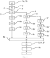
- Figure 1 shows a flow diagram showing the sequence of a possible embodiment of the method according to the invention for determining the degree of wear and for predicting the remaining useful life of a sealing arrangement of a piston compressor.
- an input matrix 3 is created in step b). For example, this includes generating the data structure from the measured vibration data 1a or the features 1b calculated therefrom in such a way that a column in the input matrix 3 represents the vibration data 1a or the features 1b calculated therefrom at a specific position of the piston and the rows of the input matrix 3, the change in the vibration data 1a or the features ( Features) 1b map over time.
- step c a simulation comprising a plurality of simulation steps is started in step c).
- step c.1 the state field-based simulation of the vibration dynamics takes place, in the present example using the time-dependent Ginzburg-Landau model 4.
- step c.1 the discrete version of the Laplace operator ⁇ is used in each simulation step recursively to the output matrix 5 of the previous simulation step.
- the output matrix 5 of the first simulation step c.1) is used as the input matrix 3 'of the second simulation step c.2), which in turn results in the output matrix 5'.
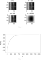
- Figure 2 shows the output matrices 5, 5' after a different number of simulation steps in the form of a heatmap.
- the illustrated embodiment of the method according to the invention is obtained after each of steps c.1) to cn).
- Output matrix 5, 5 ', 5" forms the Laplace matrix 6a, 6a', 6a".
- Figure 3 shows an example of the course of the real parts Re of the second smallest eigenvalues 6d over the n simulation steps of a simulation.
- the simulation step is identified at which the second smallest eigenvalue falls below a predefined threshold value 8a close to zero for the first time.
- This simulation step is returned as simulation result 9 in simulation time, in particular in hours, minutes or seconds, and possibly as a point in time in the future, in particular as a calendar date.
- the simulation time is calculated from the distance between the measured values, i.e. the number of sampling times N of the input matrix 3, which is generated from the vibration data 1a or the features 1b that can be calculated from it.
- falling below the predefined threshold value 8a after 750 simulation steps n can be converted into a time unit of approximately half a day when using minute averages by dividing 750 by 1440 minutes (24h x 60min).
- further simulations are carried out by repeating method steps b), creating the input matrix 3, c), carrying out a simulation step 4 and Generation of the Laplace matrix 6a, d) calculation of the eigenvalues 6b, f) selection and storage of the second smallest eigenvalue 6c, and g) identification of the number of simulation steps until the threshold value falls below zero and this value is returned in simulation time.
- a curve is adapted to the obtained simulation results 9, 9', 9" of the simulations carried out using a suitable method and the time 7 is calculated at which the curve intersects a predefined lower limit 8c.
- All simulations started (x-axis) are plotted against the number of simulation steps until the predefined threshold value 8a (y-axis) is undershot.
- the adaptation of the obtained simulation results 9, 9', 9" by local linear regression using Loess Smoothing over the entirety of the simulation results 9, 9', 9" shown in Figure 4a is given as an example.
- the time of failure or the remaining service life are calculated from the intersection of the regression curve with the predefined lower limit 8c, which in the present example is the x-axis.
- Figure 5 shows the course of the criticality index CI over time. Based on the course, it can be determined at which point in time an irreversible deterioration process begins in the sealing arrangement and the calculation of the remaining service life is triggered. This point in time can be determined based on the statistical distribution of the simulation results, especially if a certain proportion of the simulation results are below a limit value, which is in Figure 5 has the value 1 and is marked by the white line after approx. 92 days (damage onset).
- Figure 6 shows the course of the precision of the prediction error over a period of six weeks before the actual end of the useful life of the sealing arrangement, ie when a malfunction or total failure of the sealing arrangement occurs, in calendar days. How out Figure 6 As can be seen, the difference between the predicted end of the useful life and the actual occurrence of the damage event is only very small, especially in the last day before the actual failure of the sealing arrangement, which is an indicator of a very high accuracy of the predicted end of the useful life.
Landscapes
- Engineering & Computer Science (AREA)
- General Engineering & Computer Science (AREA)
- Mechanical Engineering (AREA)
- Computer Hardware Design (AREA)
- Testing Of Devices, Machine Parts, Or Other Structures Thereof (AREA)
- Control Of Positive-Displacement Pumps (AREA)
Priority Applications (6)
| Application Number | Priority Date | Filing Date | Title |
|---|---|---|---|
| EP22179017.3A EP4293228A1 (fr) | 2022-06-14 | 2022-06-14 | Procédé de prévision de la durée de vie résiduelle d'un ensemble joint d'étanchéité d'un compresseur à piston |
| EP23732036.1A EP4540527B1 (fr) | 2022-06-14 | 2023-06-08 | Procédé de prévision de la durée de vie résiduelle d'un ensemble joint d'étanchéité d'un compresseur à piston |
| KR1020257000210A KR20250022760A (ko) | 2022-06-14 | 2023-06-08 | 피스톤 압축기의 밀봉 배열체의 잔여 사용 수명을 예측하기 위한 방법 |
| JP2024570307A JP2025523361A (ja) | 2022-06-14 | 2023-06-08 | ピストン圧縮機のシール装置の残存耐用寿命を予測する方法 |
| PCT/EP2023/065418 WO2023242055A1 (fr) | 2022-06-14 | 2023-06-08 | Procédé de prédiction de la durée de vie utile restante d'un agencement d'étanchéité d'un compresseur à piston |
| CN202380046778.3A CN119301361A (zh) | 2022-06-14 | 2023-06-08 | 用于预测活塞式压缩机的密封装置的剩余使用寿命的方法 |
Applications Claiming Priority (1)
| Application Number | Priority Date | Filing Date | Title |
|---|---|---|---|
| EP22179017.3A EP4293228A1 (fr) | 2022-06-14 | 2022-06-14 | Procédé de prévision de la durée de vie résiduelle d'un ensemble joint d'étanchéité d'un compresseur à piston |
Publications (1)
| Publication Number | Publication Date |
|---|---|
| EP4293228A1 true EP4293228A1 (fr) | 2023-12-20 |
Family
ID=82492594
Family Applications (2)
| Application Number | Title | Priority Date | Filing Date |
|---|---|---|---|
| EP22179017.3A Withdrawn EP4293228A1 (fr) | 2022-06-14 | 2022-06-14 | Procédé de prévision de la durée de vie résiduelle d'un ensemble joint d'étanchéité d'un compresseur à piston |
| EP23732036.1A Active EP4540527B1 (fr) | 2022-06-14 | 2023-06-08 | Procédé de prévision de la durée de vie résiduelle d'un ensemble joint d'étanchéité d'un compresseur à piston |
Family Applications After (1)
| Application Number | Title | Priority Date | Filing Date |
|---|---|---|---|
| EP23732036.1A Active EP4540527B1 (fr) | 2022-06-14 | 2023-06-08 | Procédé de prévision de la durée de vie résiduelle d'un ensemble joint d'étanchéité d'un compresseur à piston |
Country Status (5)
| Country | Link |
|---|---|
| EP (2) | EP4293228A1 (fr) |
| JP (1) | JP2025523361A (fr) |
| KR (1) | KR20250022760A (fr) |
| CN (1) | CN119301361A (fr) |
| WO (1) | WO2023242055A1 (fr) |
Cited By (1)
| Publication number | Priority date | Publication date | Assignee | Title |
|---|---|---|---|---|
| DE102023124932A1 (de) * | 2023-09-15 | 2025-03-20 | Ebm-Papst Mulfingen Gmbh & Co. Kg | Verfahren und Vorrichtung zur Steuerung einer Strömungserzeugungseinrichtung |
Families Citing this family (1)
| Publication number | Priority date | Publication date | Assignee | Title |
|---|---|---|---|---|
| CN120489547B (zh) * | 2025-05-14 | 2025-11-18 | 温州创润塑业有限公司 | 一种基于热量和振动的接线盒密封圈寿命预测方法 |
Citations (5)
| Publication number | Priority date | Publication date | Assignee | Title |
|---|---|---|---|---|
| EP2458214A2 (fr) | 2010-11-30 | 2012-05-30 | General Electric Company | Compresseur alternatif et procédés de surveillance de son fonctionnement |
| US20160377076A1 (en) * | 2013-11-26 | 2016-12-29 | Tokuyama Corporation | State monitoring system of moving apparatus |
| EP3436877A1 (fr) | 2016-03-31 | 2019-02-06 | Fibro GmbH | Procédé de surveillance diagnostique d'une machine par analyse des oscillations |
| CN108398249B (zh) * | 2018-02-01 | 2020-04-03 | 中联重科股份有限公司 | 预测密封圈剩余寿命的方法和装置、工程机械及服务器 |
| CN112989663A (zh) * | 2021-03-19 | 2021-06-18 | 戴轶 | 一种基于复域特征值解耦非稳态振动的有限元算法及应用流程 |
-
2022
- 2022-06-14 EP EP22179017.3A patent/EP4293228A1/fr not_active Withdrawn
-
2023
- 2023-06-08 WO PCT/EP2023/065418 patent/WO2023242055A1/fr not_active Ceased
- 2023-06-08 KR KR1020257000210A patent/KR20250022760A/ko active Pending
- 2023-06-08 EP EP23732036.1A patent/EP4540527B1/fr active Active
- 2023-06-08 JP JP2024570307A patent/JP2025523361A/ja active Pending
- 2023-06-08 CN CN202380046778.3A patent/CN119301361A/zh active Pending
Patent Citations (5)
| Publication number | Priority date | Publication date | Assignee | Title |
|---|---|---|---|---|
| EP2458214A2 (fr) | 2010-11-30 | 2012-05-30 | General Electric Company | Compresseur alternatif et procédés de surveillance de son fonctionnement |
| US20160377076A1 (en) * | 2013-11-26 | 2016-12-29 | Tokuyama Corporation | State monitoring system of moving apparatus |
| EP3436877A1 (fr) | 2016-03-31 | 2019-02-06 | Fibro GmbH | Procédé de surveillance diagnostique d'une machine par analyse des oscillations |
| CN108398249B (zh) * | 2018-02-01 | 2020-04-03 | 中联重科股份有限公司 | 预测密封圈剩余寿命的方法和装置、工程机械及服务器 |
| CN112989663A (zh) * | 2021-03-19 | 2021-06-18 | 戴轶 | 一种基于复域特征值解耦非稳态振动的有限元算法及应用流程 |
Non-Patent Citations (6)
| Title |
|---|
| GASPARI ET AL., PHYSICAL REVIEW B, vol. 33, no. 5, 1986, pages 3295 - 3305 |
| HERNÄNDEZ ET AL., JOURNAL OF COMPLEX NETWORKS, vol. 2, no. 3, 2014, pages 272 - 287 |
| LOUKOPOULOS PANAGIOTIS ET AL: "Abrupt fault remaining useful life estimation using measurements from a reciprocating compressor valve failure", MECHANICAL SYSTEMS AND SIGNAL PROCESSING, vol. 121, 24 November 2018 (2018-11-24), pages 359 - 372, XP085586246, ISSN: 0888-3270, DOI: 10.1016/J.YMSSP.2018.09.033 * |
| M. FIEDLER, CZECHOSLOVAK MATHEMATICAL JOURNAL, vol. 23, no. 2, 1973, pages 298 - 305 |
| S. STROGATZ, PHYSICA D, vol. 143, 2000, pages 1 - 20 |
| ZHAO NANYANG ET AL: "Variational time-domain decomposition of reciprocating machine multi-impact vibration signals", MECHANICAL SYSTEMS AND SIGNAL PROCESSING, ELSEVIER, AMSTERDAM, NL, vol. 172, 4 March 2022 (2022-03-04), XP087008444, ISSN: 0888-3270, [retrieved on 20220304], DOI: 10.1016/J.YMSSP.2022.108977 * |
Cited By (1)
| Publication number | Priority date | Publication date | Assignee | Title |
|---|---|---|---|---|
| DE102023124932A1 (de) * | 2023-09-15 | 2025-03-20 | Ebm-Papst Mulfingen Gmbh & Co. Kg | Verfahren und Vorrichtung zur Steuerung einer Strömungserzeugungseinrichtung |
Also Published As
| Publication number | Publication date |
|---|---|
| WO2023242055A1 (fr) | 2023-12-21 |
| JP2025523361A (ja) | 2025-07-23 |
| EP4540527B1 (fr) | 2026-04-15 |
| CN119301361A (zh) | 2025-01-10 |
| EP4540527A1 (fr) | 2025-04-23 |
| KR20250022760A (ko) | 2025-02-17 |
Similar Documents
| Publication | Publication Date | Title |
|---|---|---|
| DE102016105877B4 (de) | Verfahren und Vorrichtung zur Überwachung einer Maschine | |
| EP3644038B1 (fr) | Procédé de prédiction de la maintenance des composants d'un moteur à combustion interne au moyen de capteur de bruits solidiens | |
| EP4540527B1 (fr) | Procédé de prévision de la durée de vie résiduelle d'un ensemble joint d'étanchéité d'un compresseur à piston | |
| EP3279756B1 (fr) | Dispositif de diagnostic et procédé de surveillance du fonctionnement d'une installation technique | |
| DE102019117820B4 (de) | Verfahren und Vorrichtung zur Zustandsüberwachung einer Hydraulikpumpe | |
| EP3876060B1 (fr) | Procédé et unité de calcul destinés à l'analyse des causes d'un état anormal d'une machine | |
| EP0626628A1 (fr) | Système de commande pour un entraînement hydraulique | |
| DE19961064B4 (de) | Vorrichtung und Verfahren zum Detektieren von Fehlerzuständen für einen Verbrennungsmotor | |
| DE112014005404T5 (de) | Zustandsüberwachungssystem einer Bewegungsvorrichtung | |
| EP4348825B1 (fr) | Surveiller l'état d'une machine | |
| DE102015225999A1 (de) | Verfahren zum Überprüfen des Zustandes eines Ventils | |
| EP1431927A1 (fr) | Méthode pour estimer la durée de vie résiduelle d'un appareil | |
| DE102023207829B4 (de) | Verfahren und System zum Erkennen von Anomalien in einem Satz von Signalen | |
| DE102018104665B4 (de) | Verfahren zum Betrieb einer Brennkraftmaschine, Steuereinrichtung und Brennkraftmaschine | |
| EP1189126A2 (fr) | Procédé de surveillance d'une installation | |
| EP3783448B1 (fr) | Procédé de tester d'un processus de production destiné à la fabrication de composants | |
| AT528105B1 (de) | Verfahren zur Ausfallprognose von Prüfanlagen | |
| DE102023113134A1 (de) | Verfahren und Vorrichtung zur Erfassung von Messdaten einer Maschine sowie Reifenheizpresse aufweisend eine Vorrichtung zur Erfassung von Messdaten | |
| DE102016007072A1 (de) | Verfahren zur Entwicklung eines Produktes | |
| CN121678201A (zh) | 一种柴油机电液调速器可靠性加速试验方法及系统 | |
| CN116379208A (zh) | 一种用于热轧生产线伺服阀的异常状态分析方法 | |
| EP3608737A1 (fr) | Détermination d'au moins un indicateur de processus de formage d'une servopresse |
Legal Events
| Date | Code | Title | Description |
|---|---|---|---|
| PUAI | Public reference made under article 153(3) epc to a published international application that has entered the european phase |
Free format text: ORIGINAL CODE: 0009012 |
|
| STAA | Information on the status of an ep patent application or granted ep patent |
Free format text: STATUS: THE APPLICATION HAS BEEN PUBLISHED |
|
| AK | Designated contracting states |
Kind code of ref document: A1 Designated state(s): AL AT BE BG CH CY CZ DE DK EE ES FI FR GB GR HR HU IE IS IT LI LT LU LV MC MK MT NL NO PL PT RO RS SE SI SK SM TR |
|
| STAA | Information on the status of an ep patent application or granted ep patent |
Free format text: STATUS: THE APPLICATION IS DEEMED TO BE WITHDRAWN |
|
| 18D | Application deemed to be withdrawn |
Effective date: 20240621 |