EP4293246B1 - Pince de rotor pour un ensemble frein - Google Patents
Pince de rotor pour un ensemble frein Download PDFInfo
- Publication number
- EP4293246B1 EP4293246B1 EP22461572.4A EP22461572A EP4293246B1 EP 4293246 B1 EP4293246 B1 EP 4293246B1 EP 22461572 A EP22461572 A EP 22461572A EP 4293246 B1 EP4293246 B1 EP 4293246B1
- Authority
- EP
- European Patent Office
- Prior art keywords
- clip
- lug
- rotor
- sides
- rivet
- Prior art date
- Legal status (The legal status is an assumption and is not a legal conclusion. Google has not performed a legal analysis and makes no representation as to the accuracy of the status listed.)
- Active
Links
Images

Classifications
-
- F—MECHANICAL ENGINEERING; LIGHTING; HEATING; WEAPONS; BLASTING
- F16—ENGINEERING ELEMENTS AND UNITS; GENERAL MEASURES FOR PRODUCING AND MAINTAINING EFFECTIVE FUNCTIONING OF MACHINES OR INSTALLATIONS; THERMAL INSULATION IN GENERAL
- F16D—COUPLINGS FOR TRANSMITTING ROTATION; CLUTCHES; BRAKES
- F16D65/00—Parts or details
- F16D65/02—Braking members; Mounting thereof
- F16D65/04—Bands, shoes or pads; Pivots or supporting members therefor
- F16D65/092—Bands, shoes or pads; Pivots or supporting members therefor for axially-engaging brakes, e.g. disc brakes
- F16D65/095—Pivots or supporting members therefor
- F16D65/097—Resilient means interposed between pads and supporting members or other brake parts
- F16D65/0972—Resilient means interposed between pads and supporting members or other brake parts transmitting brake reaction force, e.g. elements interposed between torque support plate and pad
-
- F—MECHANICAL ENGINEERING; LIGHTING; HEATING; WEAPONS; BLASTING
- F16—ENGINEERING ELEMENTS AND UNITS; GENERAL MEASURES FOR PRODUCING AND MAINTAINING EFFECTIVE FUNCTIONING OF MACHINES OR INSTALLATIONS; THERMAL INSULATION IN GENERAL
- F16D—COUPLINGS FOR TRANSMITTING ROTATION; CLUTCHES; BRAKES
- F16D65/00—Parts or details
- F16D65/02—Braking members; Mounting thereof
- F16D65/12—Discs; Drums for disc brakes
- F16D65/123—Discs; Drums for disc brakes comprising an annular disc secured to a hub member; Discs characterised by means for mounting
-
- F—MECHANICAL ENGINEERING; LIGHTING; HEATING; WEAPONS; BLASTING
- F16—ENGINEERING ELEMENTS AND UNITS; GENERAL MEASURES FOR PRODUCING AND MAINTAINING EFFECTIVE FUNCTIONING OF MACHINES OR INSTALLATIONS; THERMAL INSULATION IN GENERAL
- F16D—COUPLINGS FOR TRANSMITTING ROTATION; CLUTCHES; BRAKES
- F16D55/00—Brakes with substantially-radial braking surfaces pressed together in axial direction, e.g. disc brakes
- F16D55/24—Brakes with substantially-radial braking surfaces pressed together in axial direction, e.g. disc brakes with a plurality of axially-movable discs, lamellae, or pads, pressed from one side towards an axially-located member
- F16D55/26—Brakes with substantially-radial braking surfaces pressed together in axial direction, e.g. disc brakes with a plurality of axially-movable discs, lamellae, or pads, pressed from one side towards an axially-located member without self-tightening action
- F16D55/36—Brakes with a plurality of rotating discs all lying side by side
-
- F—MECHANICAL ENGINEERING; LIGHTING; HEATING; WEAPONS; BLASTING
- F16—ENGINEERING ELEMENTS AND UNITS; GENERAL MEASURES FOR PRODUCING AND MAINTAINING EFFECTIVE FUNCTIONING OF MACHINES OR INSTALLATIONS; THERMAL INSULATION IN GENERAL
- F16D—COUPLINGS FOR TRANSMITTING ROTATION; CLUTCHES; BRAKES
- F16D65/00—Parts or details
- F16D65/02—Braking members; Mounting thereof
- F16D65/12—Discs; Drums for disc brakes
- F16D65/125—Discs; Drums for disc brakes characterised by the material used for the disc body
- F16D65/126—Discs; Drums for disc brakes characterised by the material used for the disc body the material being of low mechanical strength, e.g. carbon, beryllium; Torque transmitting members therefor
-
- F—MECHANICAL ENGINEERING; LIGHTING; HEATING; WEAPONS; BLASTING
- F16—ENGINEERING ELEMENTS AND UNITS; GENERAL MEASURES FOR PRODUCING AND MAINTAINING EFFECTIVE FUNCTIONING OF MACHINES OR INSTALLATIONS; THERMAL INSULATION IN GENERAL
- F16D—COUPLINGS FOR TRANSMITTING ROTATION; CLUTCHES; BRAKES
- F16D65/00—Parts or details
- F16D65/02—Braking members; Mounting thereof
- F16D2065/13—Parts or details of discs or drums
- F16D2065/134—Connection
- F16D2065/1356—Connection interlocking
- F16D2065/1368—Connection interlocking with relative movement both radially and axially
-
- F—MECHANICAL ENGINEERING; LIGHTING; HEATING; WEAPONS; BLASTING
- F16—ENGINEERING ELEMENTS AND UNITS; GENERAL MEASURES FOR PRODUCING AND MAINTAINING EFFECTIVE FUNCTIONING OF MACHINES OR INSTALLATIONS; THERMAL INSULATION IN GENERAL
- F16D—COUPLINGS FOR TRANSMITTING ROTATION; CLUTCHES; BRAKES
- F16D65/00—Parts or details
- F16D65/02—Braking members; Mounting thereof
- F16D2065/13—Parts or details of discs or drums
- F16D2065/134—Connection
- F16D2065/1372—Connection outer circumference
-
- F—MECHANICAL ENGINEERING; LIGHTING; HEATING; WEAPONS; BLASTING
- F16—ENGINEERING ELEMENTS AND UNITS; GENERAL MEASURES FOR PRODUCING AND MAINTAINING EFFECTIVE FUNCTIONING OF MACHINES OR INSTALLATIONS; THERMAL INSULATION IN GENERAL
- F16D—COUPLINGS FOR TRANSMITTING ROTATION; CLUTCHES; BRAKES
- F16D65/00—Parts or details
- F16D65/02—Braking members; Mounting thereof
- F16D2065/13—Parts or details of discs or drums
- F16D2065/134—Connection
- F16D2065/1392—Connection elements
Definitions
- the present invention relates to a clip for the rotor of a brake assembly and to a method of fitting such a clip.
- Braking assemblies for applying a braking force to a rotating body e.g. a wheel are well known and typically comprise a brake stack of alternating rotor and stator disks.
- the braking assembly is actuated by applying a force to an actuator e.g. a piston which applies force to a pressure plate which compresses the rotor and stator disks of the brake stack together to cause deceleration and braking by friction.
- the rotor disks are provided with circumferential drive lugs via which the compressive force is applied to the rotor disks.
- Such braking mechanisms are well known and will not be described further in any detail. Brake assemblies operating in this way are common in aircraft and other vehicles.
- the rotor disks have to be made of a strong, heavy duty material such as a strong steel material or, more recently, carbon material. Carbon is preferred in many applications e.g. in aircraft, because it is more lightweight than steel for the same strength. Reduced weight of parts in or on aircraft allow for a reduction in fuel consumption and, in turn, reduced CO 2. emissions. Because of the material used, the rotor disks are expensive parts. In order to prolong the life of these disks, rotor clips are typically provided on the outer circumference of the disk e.g. on the drive lugs to provide some protection against wear of the rotor disk material. The clips transfer the drive force to the rotor drive lug. These clips, when they become worn, can be easily and relatively inexpensively replaced, allowing the more expensive rotor disks to be reused and extending their life.
- a strong, heavy duty material such as a strong steel material or, more recently, carbon material. Carbon is preferred in many applications e.g. in aircraft, because it is more lightweight than steel for the same strength
- rotor clips include a spring clip secured over the rotor drive lug by means of a rivet or similar fastener.
- Half cap clips are also known, which fit over just the end part of the drive lug.
- Floating clips are also known, which are positioned between drive lugs and allow for some movement of the clip during braking. Again, these clips are secured in position by means of rivets or pins or similar fasteners. Usually, two rivets are passed through aligned holes in the clip and the lug and are secured by rivet heads.
- the fasteners securing the clips in place are also subject to high forces acting perpendicular to the force to be transmitted to the clip and these rivets/pins are subject to bending or breakage due to these forces.
- such fasteners will have a head that protrudes beyond the surface of the clip which can also be damaged or can cause damage to other parts.
- the force on the fasteners and the forces exerted by the fasteners in known designs might not be equally distributed and hot spots can be created where the fasteners exert forces on the clip or the rotor, e.g. at the back of the rivet heads, thus causing damage to the clip and/or rotor disk. Rivets that can provide the required strength and security are expensive and difficult to manufacture and use.
- a clip for a rotor disk of a brake assembly the clip arranged to fit over an end of a lug of the rotor disk, in use, the clip having two opposing sides and an end portion across the two opposing sides, and a top portion, the top portion, the sides and the end portion each having an inner surface and an outer surface and the inner surface of the top portion, the sides and the end portion together defining a receptacle to receive the rotor lug, the clip having at least one aperture in each of the sides; and characterized in that the clip further comprising a reinforcement member extending from the inner surface of the end portion internal of the receptacle, between the two sides.
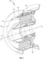
- a wheel brake assembly is shown for purposes of explanation.
- the brake assembly 100 is mounted within a wheel 102 which rotates about an axis A-A' 112.
- the brake assembly comprises a stack of alternate rotor disks 122 and stator disks 126 with the rotor disks rotatable with the wheel, and relative to the stator disks, about axis 112.
- To decelerate or brake rotation of the wheel pressure is applied by means of actuators in the axial direction A-A' to the brake stack to compress the rotor and stator disks together, causing friction between the rotor and stator disks and thus slowing the wheel.
- the rotor disks have rotor lugs 124 defined around their circumference and extending radially outwards with respect to the axis of rotation 112. Slots 125, shown in Fig. 2 , are defined between adjacent lugs 124. Torque bars 108 acts as drive lugs that engage the wheel with the rotor disks via the rotor lugs.
- the rotor lugs 124 may be provided with protective clips 123 via which the torque is transferred from the torque bars 108 to the rotor lugs 124, and hence to the rotor disk.
- the operation of the brake assembly will cause the brake clips 123 to wear before the rotor disk material wears, and the clips 123 can be removed and new clips fitted, without needing to replace the entire rotor disk.
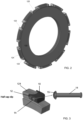
- Fig. 2 shows a rotor disk 122 having lugs 124 provided around its circumference, with clips 123 attached to the ends of the rotor lugs.
- these clips are attached to the rotor disks or rotor lugs by means of rivets that pass through the rotor lug from one side to the other.
- An example of such known clip designs is shown in Fig. 3 .
- Fig. 3 shows a so-called half cap clip 10 which has at least one rivet aperture 12 (in this example, there are two rivet apertures 12).
- the clip 10 is shaped to fit over the end of a rotor lug 124 and is secured to the lug by means of rivets 14 secured to the side of the lug through the clip apertures 12.
- these rivets pass through the width of the rotor lug and can be subjected to bending forces. They can be expensive and difficult to manufacture and install and a hotspot of force can occur around the region of the rivet head 15.
- the clip 300 provides an alternative to the half-cap clip described above for securing the clip to the lug, which allows for improved stress distribution, less risk of damage to the carbon of the brake and less risk of bending of the rivet(s), particularly when used on relatively wide rotor lugs where the rivet needs to be long.
- the clip 300 is shaped as a cap to fit over the end of a rotor lug in a manner similar to the conventional clip described above.
- the clip has a substantially flat planar, top portion 301 that extends in a first plane, a first side 311 and an opposite, second side 312 spaced from the first side by the top surface, and an end portion 303 that extends in a second plane from the top portion.
- the top portion may be square or rectangular or may be provided with a curved edge 330 as shown in the Figs.
- the top portion 301, the first and second sides 311, 312, and the end portion 303 each have an inner surface and an outer surface, and the inner surfaces of the top portion, the sides and the end portion together define a recess 320 to receive an end of a lug onto which the clip is mounted, in use.
- Transitions between the top portion 301, the end portion 303, and/or the sides 311, 312 may include sloped or rounded bends or corners 304, 305. Alternatively, the corners may be sharp.
- the shape of the clip is such that the end portion 303 lies flat against the end of the lug 124 so that a normal force is transferred through the flat surfaces.
- Each of the first and second sides 311, 312 is provided with an aperture 322 that, when mounted on the end of the lug 124, aligns with a passage (not shown) through the lug such that a rivet 400 can be passed through the aperture 322 in the first side 311 of the clip, the passage through the lug and out through the aperture 322 in the second side 312 of the clip to secure the clip 300 to the lug 124 when mounted thereon, in use.
- additional security and better force distribution can be provided by using two rivets as shown in this example, in which case, each side has two apertures and the lug has two passages. More than two rivets could, in theory, also be used if space provides.
- the rivet(s) has/have a rivet head 401 and a rivet body 402 extending from the head along a rivet axis X.
- the size of the aperture 322 is such as to allow passage of the rivet body therethrough but is smaller than the rivet head such that the rivet head stops against the side at the aperture and cannot pass through the aperture.
- the length of the rivet is such that when the rivet is fully inserted, the head abuts against one of the clip sides at the outer surface of the side, the rivet body spans the recess 320 and the other end 403 of the rivet opposite the head 401 protrudes from the aperture in the other side beyond the outer surface of the other side.
- the end 403 protrudes past the outer surface of the other side by about the same distance as the rivet head protrudes from the first side.
- a cap or fastener or other finish may be provided on the protruding end 403 to prevent the rivet being withdrawn back through the passage inadvertently. To replace the clip, however, this can be removed so that the rivet(s) can be withdrawn and the clip can be disassembled. Seals and/or washers may be provided between the rivet head and the side of the clip.
- the clip of the present disclosure also has a reinforcement member 500 that extends from the inner surface of the end portion 303 along the recess 320.
- the reinforcement member 500 extends substantially parallel to and between the first and second sides 311, 312. In the example shown, the reinforcement member 500 extends from around the middle of the end portion 303 (defined with respect of the length between the two sides 311, 312), but the reinforcement member could, if desired, be spaced closer to the first side or closer to the second side.
- the reinforcement member 500 also has one or more apertures 501 that align with the apertures 322 in the sides 311, 312.
- the number of apertures in the reinforcement member should match the number of apertures in the sides (or could, in theory be more if there is a need to provide redundant apertures for e.g. manufacturing reasons) and thus will also match the number of rivets used.
- the width and length of the reinforcement member is selected such that it will fit into a slot 600 in the end of the lug.
- the clip 300 To mount the clip 300 to the lug 124, the clip is positioned over the end of the lug such that the top portion 301 rests against the top of the lug and the end portion 303 abuts against the end face of the lug.
- the reinforcement member 500 will locate in the slot 600 in the lug.
- the sides 311, 312 will rest against or be closely adjacent the sides of the lug.
- the aperture or apertures are aligned with the passage/passages through the lug.
- The, or each, rivet is then inserted through the aperture 322 in the first side, through the passage through the lug and the aperture 501 in the reinforcing member 500 and out through the aperture 322 in the second side 312 until the rivet head abuts against the first side.
- the other end of the rivet is then fastened or secured and the clip is held in position.
- the reinforcement member 500 adds further support to the rivets as they pass through the lug to reduce or prevent bending of the rivets. This is particularly important where the distance the rivet has to extend through the lug is great because longer rivets may be subjected to bending in extreme conditions and this reinforcement member mitigates this problem.
- the clip is therefore small, light, simple and inexpensive to manufacture and assemble and allows for a better resistance to bending of the rivet(s).
Landscapes
- Engineering & Computer Science (AREA)
- General Engineering & Computer Science (AREA)
- Mechanical Engineering (AREA)
- Connection Of Plates (AREA)
Claims (15)
- Pince pour un disque de rotor d'un ensemble frein, la pince (300) étant agencée pour s'adapter sur une extrémité d'une patte du disque de rotor, la pince ayant deux côtés opposés (311, 312) et une partie d'extrémité (303) sur les deux côtés opposés, et une partie supérieure (301), la partie supérieure, les côtés et la partie d'extrémité ayant chacun une surface intérieure et une surface extérieure, et la surface intérieure de la partie supérieure, des côtés et de la partie d'extrémité définissant ensemble un évidement (320) configuré pour recevoir la patte de rotor, pendant l'utilisation, la pince ayant au moins une ouverture (322) dans chacun des côtés ; et caractérisée en ce que la pince comprend également un élément de renforcement (500) s'étendant à partir de la surface intérieure de la partie d'extrémité interne de l'évidement, entre les deux côtés.
- Pince selon la revendication 1 ou 2, la pince ayant deux ouvertures (322) dans chacun des côtés.
- Pince selon la revendication 1, comprenant également un rivet (400) configuré pour passer à travers ladite ou chaque ouverture dans le premier côté, à travers un passage dans la patte, et sortir à travers ladite ou chaque ouverture dans le second côté.
- Pince selon la revendication 3, dans laquelle le rivet a une tête de rivet et un corps de rivet s'étendant à partir de la tête de rivet le long d'un axe de rivet.
- Pince selon la revendication 4, dans laquelle la tête de broche s'étend radialement vers l'extérieur au-delà de l'étendue du corps de broche.
- Pince selon la revendication 3 ou 4, dans laquelle le corps de rivet a une extrémité opposée à la tête de rivet, l'extrémité étant configurée pour recevoir un capuchon.
- Pince selon une quelconque revendication précédente, dans laquelle l'élément de renforcement s'étend à partir du milieu d'une longueur de la partie d'extrémité telle que définie entre les premier et second côtés.
- Pince selon une quelconque revendication précédente, dans laquelle l'élément de renforcement s'étend sensiblement parallèlement aux premier et second côtés, et entre ceux-ci.
- Disque de rotor d'un ensemble frein pourvu d'une pluralité de pattes de rotor autour de sa circonférence, et s'étendant radialement à partir de celle-ci ; et une pince telle que revendiquée dans une quelconque revendication précédente montée sur chaque patte de rotor.
- Ensemble frein comprenant une pluralité de disques de rotor tels que revendiqués dans la revendication 9 et une pluralité de disques de stator, les disques de stator et les disques de rotor étant agencés en alternance pour former un empilement de freins.
- Ensemble roue comprenant une roue ayant un diamètre intérieur à l'intérieur duquel est monté un ensemble frein tel que revendiqué dans la revendication 10.
- Ensemble roue tel que revendiqué dans la revendication 11, la roue ayant un diamètre extérieur sur lequel est monté un pneu.
- Ensemble roue tel que revendiqué dans la revendication 11 ou 12, qui est un ensemble roue pour le train d'atterrissage d'un aéronef.
- Procédé d'adaptation d'un ensemble pince tel que revendiqué dans l'une quelconque des revendications 1 à 8 sur un disque de rotor d'un ensemble frein, le procédé comprenant l'adaptation de la pince sur une extrémité d'une patte de rotor du disque de rotor de telle sorte que la surface intérieure de la partie supérieure repose sur une partie supérieure de la patte de rotor, la surface intérieure de la partie d'extrémité s'adapte contre une extrémité avant de la patte, les côtés sont positionnés adjacents aux côtés respectifs de la patte et caractérisé par l'adaptation de l'élément de renforcement dans une fente définie à travers la patte et dans lequel les ouvertures sont alignées avec un passage à travers la patte.
- Procédé selon la revendication 14 dépendant de la revendication 3, comprenant également la fourniture du rivet à travers la pince et la patte.
Priority Applications (2)
| Application Number | Priority Date | Filing Date | Title |
|---|---|---|---|
| EP22461572.4A EP4293246B1 (fr) | 2022-06-13 | 2022-06-13 | Pince de rotor pour un ensemble frein |
| US18/330,215 US12486878B2 (en) | 2022-06-13 | 2023-06-06 | Rotor clip for brake assembly |
Applications Claiming Priority (1)
| Application Number | Priority Date | Filing Date | Title |
|---|---|---|---|
| EP22461572.4A EP4293246B1 (fr) | 2022-06-13 | 2022-06-13 | Pince de rotor pour un ensemble frein |
Publications (2)
| Publication Number | Publication Date |
|---|---|
| EP4293246A1 EP4293246A1 (fr) | 2023-12-20 |
| EP4293246B1 true EP4293246B1 (fr) | 2025-02-19 |
Family
ID=82058470
Family Applications (1)
| Application Number | Title | Priority Date | Filing Date |
|---|---|---|---|
| EP22461572.4A Active EP4293246B1 (fr) | 2022-06-13 | 2022-06-13 | Pince de rotor pour un ensemble frein |
Country Status (2)
| Country | Link |
|---|---|
| US (1) | US12486878B2 (fr) |
| EP (1) | EP4293246B1 (fr) |
Families Citing this family (2)
| Publication number | Priority date | Publication date | Assignee | Title |
|---|---|---|---|---|
| EP4290093B1 (fr) * | 2022-06-08 | 2025-01-29 | Goodrich Corporation | Pince de rotor pour ensembles freins |
| FR3163417A1 (fr) * | 2024-06-13 | 2025-12-19 | Safran Ceramics | Disque de frein destine a une roue de vehicule |
Family Cites Families (30)
| Publication number | Priority date | Publication date | Assignee | Title |
|---|---|---|---|---|
| US3800392A (en) * | 1970-11-05 | 1974-04-02 | Goodyear Tire & Rubber | Graphite and/or carbon disk with removable wear faces |
| US3907076A (en) * | 1971-05-24 | 1975-09-23 | Goodyear Aerospace Corp | Key slot segments for driving brake discs |
| US3757907A (en) * | 1971-05-24 | 1973-09-11 | Goodyear Tire & Rubber | Key slot segments for driving brake discs |
| US3731769A (en) * | 1971-10-13 | 1973-05-08 | Goodrich Co B F | Friction member assembly |
| US3902578A (en) * | 1973-10-05 | 1975-09-02 | Goodyear Aerospace Corp | Segmented friction disk for brake or clutch |
| US3972395A (en) * | 1974-03-29 | 1976-08-03 | The Bendix Corporation | Oxidation inhibiting caps for carbon friction disc |
| US3927740A (en) * | 1974-07-01 | 1975-12-23 | Goodyear Aerospace Corp | Brake disk with tapered key way |
| US4007814A (en) * | 1976-02-05 | 1977-02-15 | Goodyear Aerospace Corporation | Carbon brake disk with cast keyslot reinforcement members |
| US4469204A (en) * | 1983-01-28 | 1984-09-04 | The B. F. Goodrich Company | Brake apparatus |
| US4465165A (en) * | 1983-01-28 | 1984-08-14 | The B. F. Goodrich Company | Brake apparatus |
| US4511021A (en) * | 1983-04-21 | 1985-04-16 | The B. F. Goodrich Company | Brake apparatus |
| US4557356A (en) * | 1984-04-30 | 1985-12-10 | Goodyear Aerospace Corporation | Brake disk and keyslot reinforcements therefor |
| US4747473A (en) * | 1986-06-19 | 1988-05-31 | The B. F. Goodrich Company | Segmented friction brake or clutch disc assembly |
| US4784246A (en) * | 1987-02-18 | 1988-11-15 | The B. F. Goodrich Company | Brake apparatus |
| US4863001A (en) * | 1987-02-18 | 1989-09-05 | The Bf Goodrich Company | Brake apparatus |
| FR2629888B1 (fr) * | 1988-04-08 | 1991-02-22 | Messier Hispano Sa | Disque de rotor de frein en carbone equipe de cavaliers de renforcement |
| FR2719879B1 (fr) * | 1994-05-11 | 1996-06-07 | Messier Bugatti | Dispositif de renforcement pour disques de frein en carbone, et disque de frein équipé de tels dispositifs. |
| US6419056B1 (en) * | 1998-10-29 | 2002-07-16 | Aircraft Braking Systems Corp. | Apparatus for aircraft brake thermal management |
| US7303055B2 (en) * | 2004-04-15 | 2007-12-04 | Goodrich Corporation | Method and apparatus for protecting a friction brake disc |
| US7442443B2 (en) * | 2005-05-31 | 2008-10-28 | Goodrich Corporation | Chromium-nickel stainless steel alloy article having oxide coating formed from the base metal suitable for brake apparatus |
| US20070193836A1 (en) * | 2006-02-23 | 2007-08-23 | Walker Terence B | Method and brake disc with composite insert member |
| US7802758B2 (en) * | 2007-05-04 | 2010-09-28 | Honeywell International Inc. | Load-distributing rotor insert for aircraft brakes |
| US8418817B2 (en) * | 2011-06-29 | 2013-04-16 | Arvinmeritor Technology, Llc | Brake assembly having a mounting clip |
| US20160279710A1 (en) * | 2015-03-25 | 2016-09-29 | Goodrich Corporation | Aircraft brake rotor clip repair methods |
| US10221905B2 (en) * | 2016-11-09 | 2019-03-05 | Goodrich Corporation | Bridged clip retainer for brake system |
| US10436265B2 (en) * | 2017-08-10 | 2019-10-08 | Goodrich Corporation | Rivet-less rotor clip design |
| US10941823B2 (en) * | 2017-11-27 | 2021-03-09 | Goodrich Corporation | Segmented wear liner |
| EP4155570B1 (fr) * | 2021-09-24 | 2024-04-17 | Goodrich Corporation | Pince de rotor pour ensemble frein |
| US11913510B2 (en) * | 2021-09-27 | 2024-02-27 | Goodrich Corporation | Rotor clip apparatus and systems |
| US12264717B2 (en) * | 2022-05-24 | 2025-04-01 | Goodrich Corporation | Reduced drag stator clip |
-
2022
- 2022-06-13 EP EP22461572.4A patent/EP4293246B1/fr active Active
-
2023
- 2023-06-06 US US18/330,215 patent/US12486878B2/en active Active
Also Published As
| Publication number | Publication date |
|---|---|
| US20230407934A1 (en) | 2023-12-21 |
| EP4293246A1 (fr) | 2023-12-20 |
| US12486878B2 (en) | 2025-12-02 |
Similar Documents
| Publication | Publication Date | Title |
|---|---|---|
| US12486878B2 (en) | Rotor clip for brake assembly | |
| EP3563073B1 (fr) | Frein à disque à rotor flottant avec fixation d'anneau d'extenseur ondulé | |
| US9303705B2 (en) | Brake disc and mounting arrangement for a brake disc | |
| EP0398092A1 (fr) | Support de transmission de couple pour des entraînements à couple de freinage | |
| WO2010027896A1 (fr) | Ensemble de rotor de frein et de moyeu de roue | |
| US6340075B1 (en) | Three run disk brake stack and method of assembly | |
| EP4155569A1 (fr) | Agrafe rotor de demi-capot | |
| EP4283154B1 (fr) | Clip de stator pour ensemble frein | |
| US12498008B2 (en) | Rotor clip for brake assembly | |
| US12571442B2 (en) | Rotor clip for brake assembly | |
| EP4155570B1 (fr) | Pince de rotor pour ensemble frein | |
| EP0096553B1 (fr) | Assemblages de disque pour freins | |
| EP4290093B1 (fr) | Pince de rotor pour ensembles freins | |
| US20040079595A1 (en) | Friction-lining segment, friction lining and process for its manufacture | |
| EP3708861B1 (fr) | Revêtement d'usure à fente segmenté intégré doté d'un noyau structural en carbone ou en céramique | |
| KR102066070B1 (ko) | 스퍼 마운팅 구조의 제동디스크 | |
| EP3404283B1 (fr) | Tube de torsion | |
| EP4414581B1 (fr) | Utilisation d'une surface de réaction profilée dans des applications de barre de couple hybride | |
| US12331801B2 (en) | Stator clip for brake assembly |
Legal Events
| Date | Code | Title | Description |
|---|---|---|---|
| PUAI | Public reference made under article 153(3) epc to a published international application that has entered the european phase |
Free format text: ORIGINAL CODE: 0009012 |
|
| STAA | Information on the status of an ep patent application or granted ep patent |
Free format text: STATUS: THE APPLICATION HAS BEEN PUBLISHED |
|
| AK | Designated contracting states |
Kind code of ref document: A1 Designated state(s): AL AT BE BG CH CY CZ DE DK EE ES FI FR GB GR HR HU IE IS IT LI LT LU LV MC MK MT NL NO PL PT RO RS SE SI SK SM TR |
|
| STAA | Information on the status of an ep patent application or granted ep patent |
Free format text: STATUS: REQUEST FOR EXAMINATION WAS MADE |
|
| 17P | Request for examination filed |
Effective date: 20240620 |
|
| RBV | Designated contracting states (corrected) |
Designated state(s): AL AT BE BG CH CY CZ DE DK EE ES FI FR GB GR HR HU IE IS IT LI LT LU LV MC MK MT NL NO PL PT RO RS SE SI SK SM TR |
|
| GRAP | Despatch of communication of intention to grant a patent |
Free format text: ORIGINAL CODE: EPIDOSNIGR1 |
|
| STAA | Information on the status of an ep patent application or granted ep patent |
Free format text: STATUS: GRANT OF PATENT IS INTENDED |
|
| RIC1 | Information provided on ipc code assigned before grant |
Ipc: F16D 65/12 20060101ALI20240903BHEP Ipc: F16D 55/36 20060101AFI20240903BHEP |
|
| INTG | Intention to grant announced |
Effective date: 20240919 |
|
| GRAS | Grant fee paid |
Free format text: ORIGINAL CODE: EPIDOSNIGR3 |
|
| GRAA | (expected) grant |
Free format text: ORIGINAL CODE: 0009210 |
|
| STAA | Information on the status of an ep patent application or granted ep patent |
Free format text: STATUS: THE PATENT HAS BEEN GRANTED |
|
| AK | Designated contracting states |
Kind code of ref document: B1 Designated state(s): AL AT BE BG CH CY CZ DE DK EE ES FI FR GB GR HR HU IE IS IT LI LT LU LV MC MK MT NL NO PL PT RO RS SE SI SK SM TR |
|
| REG | Reference to a national code |
Ref country code: GB Ref legal event code: FG4D |
|
| REG | Reference to a national code |
Ref country code: CH Ref legal event code: EP |
|
| REG | Reference to a national code |
Ref country code: DE Ref legal event code: R096 Ref document number: 602022010816 Country of ref document: DE |
|
| REG | Reference to a national code |
Ref country code: IE Ref legal event code: FG4D |
|
| REG | Reference to a national code |
Ref country code: NL Ref legal event code: MP Effective date: 20250219 |
|
| PG25 | Lapsed in a contracting state [announced via postgrant information from national office to epo] |
Ref country code: RS Free format text: LAPSE BECAUSE OF FAILURE TO SUBMIT A TRANSLATION OF THE DESCRIPTION OR TO PAY THE FEE WITHIN THE PRESCRIBED TIME-LIMIT Effective date: 20250519 |
|
| PG25 | Lapsed in a contracting state [announced via postgrant information from national office to epo] |
Ref country code: FI Free format text: LAPSE BECAUSE OF FAILURE TO SUBMIT A TRANSLATION OF THE DESCRIPTION OR TO PAY THE FEE WITHIN THE PRESCRIBED TIME-LIMIT Effective date: 20250219 |
|
| PG25 | Lapsed in a contracting state [announced via postgrant information from national office to epo] |
Ref country code: PL Free format text: LAPSE BECAUSE OF FAILURE TO SUBMIT A TRANSLATION OF THE DESCRIPTION OR TO PAY THE FEE WITHIN THE PRESCRIBED TIME-LIMIT Effective date: 20250219 |
|
| PG25 | Lapsed in a contracting state [announced via postgrant information from national office to epo] |
Ref country code: ES Free format text: LAPSE BECAUSE OF FAILURE TO SUBMIT A TRANSLATION OF THE DESCRIPTION OR TO PAY THE FEE WITHIN THE PRESCRIBED TIME-LIMIT Effective date: 20250219 |
|
| REG | Reference to a national code |
Ref country code: LT Ref legal event code: MG9D |
|
| PG25 | Lapsed in a contracting state [announced via postgrant information from national office to epo] |
Ref country code: IS Free format text: LAPSE BECAUSE OF FAILURE TO SUBMIT A TRANSLATION OF THE DESCRIPTION OR TO PAY THE FEE WITHIN THE PRESCRIBED TIME-LIMIT Effective date: 20250619 Ref country code: NO Free format text: LAPSE BECAUSE OF FAILURE TO SUBMIT A TRANSLATION OF THE DESCRIPTION OR TO PAY THE FEE WITHIN THE PRESCRIBED TIME-LIMIT Effective date: 20250519 |
|
| PG25 | Lapsed in a contracting state [announced via postgrant information from national office to epo] |
Ref country code: NL Free format text: LAPSE BECAUSE OF FAILURE TO SUBMIT A TRANSLATION OF THE DESCRIPTION OR TO PAY THE FEE WITHIN THE PRESCRIBED TIME-LIMIT Effective date: 20250219 |
|
| PG25 | Lapsed in a contracting state [announced via postgrant information from national office to epo] |
Ref country code: HR Free format text: LAPSE BECAUSE OF FAILURE TO SUBMIT A TRANSLATION OF THE DESCRIPTION OR TO PAY THE FEE WITHIN THE PRESCRIBED TIME-LIMIT Effective date: 20250219 |
|
| PG25 | Lapsed in a contracting state [announced via postgrant information from national office to epo] |
Ref country code: PT Free format text: LAPSE BECAUSE OF FAILURE TO SUBMIT A TRANSLATION OF THE DESCRIPTION OR TO PAY THE FEE WITHIN THE PRESCRIBED TIME-LIMIT Effective date: 20250620 Ref country code: LV Free format text: LAPSE BECAUSE OF FAILURE TO SUBMIT A TRANSLATION OF THE DESCRIPTION OR TO PAY THE FEE WITHIN THE PRESCRIBED TIME-LIMIT Effective date: 20250219 |
|
| PGFP | Annual fee paid to national office [announced via postgrant information from national office to epo] |
Ref country code: FR Payment date: 20250520 Year of fee payment: 4 |
|
| PG25 | Lapsed in a contracting state [announced via postgrant information from national office to epo] |
Ref country code: BG Free format text: LAPSE BECAUSE OF FAILURE TO SUBMIT A TRANSLATION OF THE DESCRIPTION OR TO PAY THE FEE WITHIN THE PRESCRIBED TIME-LIMIT Effective date: 20250219 Ref country code: GR Free format text: LAPSE BECAUSE OF FAILURE TO SUBMIT A TRANSLATION OF THE DESCRIPTION OR TO PAY THE FEE WITHIN THE PRESCRIBED TIME-LIMIT Effective date: 20250520 |
|
| REG | Reference to a national code |
Ref country code: AT Ref legal event code: MK05 Ref document number: 1768518 Country of ref document: AT Kind code of ref document: T Effective date: 20250219 |
|
| PG25 | Lapsed in a contracting state [announced via postgrant information from national office to epo] |
Ref country code: SE Free format text: LAPSE BECAUSE OF FAILURE TO SUBMIT A TRANSLATION OF THE DESCRIPTION OR TO PAY THE FEE WITHIN THE PRESCRIBED TIME-LIMIT Effective date: 20250219 |
|
| PG25 | Lapsed in a contracting state [announced via postgrant information from national office to epo] |
Ref country code: SM Free format text: LAPSE BECAUSE OF FAILURE TO SUBMIT A TRANSLATION OF THE DESCRIPTION OR TO PAY THE FEE WITHIN THE PRESCRIBED TIME-LIMIT Effective date: 20250219 |
|
| PG25 | Lapsed in a contracting state [announced via postgrant information from national office to epo] |
Ref country code: DK Free format text: LAPSE BECAUSE OF FAILURE TO SUBMIT A TRANSLATION OF THE DESCRIPTION OR TO PAY THE FEE WITHIN THE PRESCRIBED TIME-LIMIT Effective date: 20250219 |
|
| PG25 | Lapsed in a contracting state [announced via postgrant information from national office to epo] |
Ref country code: IT Free format text: LAPSE BECAUSE OF FAILURE TO SUBMIT A TRANSLATION OF THE DESCRIPTION OR TO PAY THE FEE WITHIN THE PRESCRIBED TIME-LIMIT Effective date: 20250219 |
|
| PG25 | Lapsed in a contracting state [announced via postgrant information from national office to epo] |
Ref country code: AT Free format text: LAPSE BECAUSE OF FAILURE TO SUBMIT A TRANSLATION OF THE DESCRIPTION OR TO PAY THE FEE WITHIN THE PRESCRIBED TIME-LIMIT Effective date: 20250219 |
|
| PG25 | Lapsed in a contracting state [announced via postgrant information from national office to epo] |
Ref country code: EE Free format text: LAPSE BECAUSE OF FAILURE TO SUBMIT A TRANSLATION OF THE DESCRIPTION OR TO PAY THE FEE WITHIN THE PRESCRIBED TIME-LIMIT Effective date: 20250219 Ref country code: CZ Free format text: LAPSE BECAUSE OF FAILURE TO SUBMIT A TRANSLATION OF THE DESCRIPTION OR TO PAY THE FEE WITHIN THE PRESCRIBED TIME-LIMIT Effective date: 20250219 |
|
| PG25 | Lapsed in a contracting state [announced via postgrant information from national office to epo] |
Ref country code: RO Free format text: LAPSE BECAUSE OF FAILURE TO SUBMIT A TRANSLATION OF THE DESCRIPTION OR TO PAY THE FEE WITHIN THE PRESCRIBED TIME-LIMIT Effective date: 20250219 |
|
| PG25 | Lapsed in a contracting state [announced via postgrant information from national office to epo] |
Ref country code: SK Free format text: LAPSE BECAUSE OF FAILURE TO SUBMIT A TRANSLATION OF THE DESCRIPTION OR TO PAY THE FEE WITHIN THE PRESCRIBED TIME-LIMIT Effective date: 20250219 |
|
| REG | Reference to a national code |
Ref country code: DE Ref legal event code: R097 Ref document number: 602022010816 Country of ref document: DE |
|
| PLBE | No opposition filed within time limit |
Free format text: ORIGINAL CODE: 0009261 |
|
| STAA | Information on the status of an ep patent application or granted ep patent |
Free format text: STATUS: NO OPPOSITION FILED WITHIN TIME LIMIT |
|
| REG | Reference to a national code |
Ref country code: CH Ref legal event code: L10 Free format text: ST27 STATUS EVENT CODE: U-0-0-L10-L00 (AS PROVIDED BY THE NATIONAL OFFICE) Effective date: 20251231 |
|
| REG | Reference to a national code |
Ref country code: DE Ref legal event code: R119 Ref document number: 602022010816 Country of ref document: DE |
|
| REG | Reference to a national code |
Ref country code: CH Ref legal event code: H13 Free format text: ST27 STATUS EVENT CODE: U-0-0-H10-H13 (AS PROVIDED BY THE NATIONAL OFFICE) Effective date: 20260127 |
|
| 26N | No opposition filed |
Effective date: 20251120 |
|
| PG25 | Lapsed in a contracting state [announced via postgrant information from national office to epo] |
Ref country code: MC Free format text: LAPSE BECAUSE OF FAILURE TO SUBMIT A TRANSLATION OF THE DESCRIPTION OR TO PAY THE FEE WITHIN THE PRESCRIBED TIME-LIMIT Effective date: 20250219 |
|
| PG25 | Lapsed in a contracting state [announced via postgrant information from national office to epo] |
Ref country code: LU Free format text: LAPSE BECAUSE OF NON-PAYMENT OF DUE FEES Effective date: 20250613 |
|
| REG | Reference to a national code |
Ref country code: BE Ref legal event code: MM Effective date: 20250630 |
|
| PG25 | Lapsed in a contracting state [announced via postgrant information from national office to epo] |
Ref country code: DE Free format text: LAPSE BECAUSE OF NON-PAYMENT OF DUE FEES Effective date: 20260101 Ref country code: IE Free format text: LAPSE BECAUSE OF NON-PAYMENT OF DUE FEES Effective date: 20250613 |
|
| PG25 | Lapsed in a contracting state [announced via postgrant information from national office to epo] |
Ref country code: BE Free format text: LAPSE BECAUSE OF NON-PAYMENT OF DUE FEES Effective date: 20250630 |
|
| PG25 | Lapsed in a contracting state [announced via postgrant information from national office to epo] |
Ref country code: CH Free format text: LAPSE BECAUSE OF NON-PAYMENT OF DUE FEES Effective date: 20250630 |